Pump Handbook by Igor J. Karassik, Joseph P. Messina, Paul Cooper, Charles C. Heald - 3rd edition
Подождите немного. Документ загружается.

2.122 CHAPTER TWO
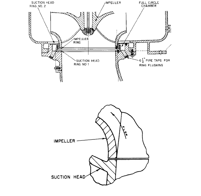
FIGURE 50 Two sets of rings with space between for flushing water (Flowserve Corporation)
FIGURE 51 A leakage joint with axial clearance
Leakage joints with axial clearance are not popular for double-suction pumps because
a very close tolerance is required in machining the fit of the rings in reference to the cen-
terline of the volute waterways. Joints with radial clearances, however, enable some shift-
ing of the impeller for centering. The only adverse effect is a slight inequality in the
lengths of the leakage paths on the two sides.
So far, this discussion has treated only those leakage joints located adjacent to the
impeller eye or at the smallest outside shroud diameter. Designs have been made where
the leakage joint is at the periphery of the impeller. In a vertical pump, this design is
advantageous because the space between the joint and the suction waterways is open and
so sand or grit cannot collect. Because of rubbing speed and because the impeller diame-
ters used in the same casing vary over a wide range, the design is impractical in regular
pump lines.
Mounting Stationary Wearing Rings In small single-suction pumps with suction
heads, a stationary wearing ring is usually pressed into a bore in the head and may or
may not be further locked by several set screws located half in the head and half in the
ring (refer to Figure 41). Larger pumps often use an L-type ring with the flange held
against a face on the head. In axially split casing pumps, the cylindrical casing bore (in
which the casing ring will be mounted) should be slightly larger than the outside diame-
ter of the ring. Unless some clearance is provided, distortion of the ring may occur when
the two casing halves are assembled. However, the joint between the casing ring and the
2.2.1 CENTRIFUGAL PUMP: MAJOR COMPONENTS 2.123
casing must be tight enough to prevent leakage.This is usually provided by a radial metal-
to-metal joint (refer to Figure 43) arranged so that the discharge pressure presses the ring
against the casing surface.
As it is not desirable for the casing ring of an axially split casing pump to be pinched
by the casing, the ring will not be held tightly enough to prevent its rotation unless spe-
cial provisions are made to keep it in place. One means of accomplishing this is to place a
pin in the casing that will project into a hole bored in the ring or, conversely, to provide a
pin in the ring that will fit into a hole bored in the casing or into a recess at the casing
split joint.
Another method is to have a tongue on the casing ring that extends around 180° and
engages a corresponding groove in one-half of the casing. This method can be used with
casing rings having a central flange by making the diameter of the flange larger for 180°
and cutting a deeper groove in that half of the casing.
Many methods are used for holding impeller rings on the impeller. Probably the simplest
is to rely on a press fit of the ring on the impeller or, if the ring is of proper material, on a
shrink fit. Designers do not usually feel that a press fit is sufficient and often add several
machine screws or set screws located half in the ring and half in the impeller, as in Figure 41.
An alternative to axial machine screws being located half in the ring and half in the
impeller is the radial pin, which goes through the center of the ring into the impeller (or
from the inside of the impeller eye outward into the ring).This pinning method avoids hav-
ing to drill and tap holes half in a hardened wearing ring and half in a softer impeller hub.
For higher speeds, installing the radial pins from the inside of the impeller eye outward
into the wearing ring captures the pins and protects against pin loss, especially at higher
operating speeds. Generally, some additional locking method is used rather than relying
solely on friction between the ring and the impeller.
In the design of impeller rings, consideration has to be given to the stretch of the ring
caused by centrifugal force, especially if the pump is of a high-speed design for the capac-
ity involved. For example, some pumps operate at speeds that would cause the rings to
become loose if only a press fit is used. For such pumps, shrink fits should be used or,
preferably, impeller rings should be eliminated.
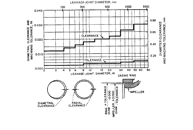
Wearing-Ring Clearances Typical clearance and tolerance standards for nongalling
wearing-joint metals in general service pumps are shown in Figure 52. They apply to the
FIGURE 52 Wearing-ring clearances for single-stage pumps using nongalling materials
2.124 CHAPTER TWO
following combinations: (1) bronze with a dissimilar bronze, (2) cast-iron with bronze, (3)
steel with bronze, (4) Monel metal with bronze, and (5) cast-iron with cast iron. If the met-
als gall easily (like the chrome steels), the values given should be increased by 0.002 to
0.004 in.
The tolerance indicated is positive for the casing ring and negative for the impeller hub
or impeller ring.
In a single-stage pump with a joint of nongalling components, the correct machining
dimension for a casing-ring diameter of 9.000 in would be 9.000 plus 0.003 and minus
0.000 in. For the impeller hub or ring, the values would be 9.000 minus 0.018 (or 8.982)
plus 0.000 and minus 0.003 in. Diametral clearances would be between 0.018 and 0.024 in.
Obviously, clearances and tolerances are not translated into SI units by merely using con-
version multipliers; they are rounded off as they are in the USCS system. The SI values
for the previous USCS examples given are outlined here.
For a single-stage pump with a casing ring diameter of 230 millimeters, the machining
dimensions would be as follows:
Casing ring 230 plus 0.08 and minus 0.00 mm
Impeller hub 230 minus 0.50 (229.5) plus 0.00 and minus 0.08 mm
Diametral clearances Between 0.50 and 0.66 mm
Naturally, the manufacturer’s recommendation for ring clearances and tolerances
should be followed.
AXIAL THRUST ______________________________________________________
Axial Thrust in Single-Stage Pumps with Closed Impellers
The pressures generated
by a centrifugal pump exert forces on both stationary and rotating parts. The design of
these parts balances some of these forces, but separate means may be required to coun-
terbalance others.
An axial hydraulic thrust on an impeller is the sum of the unbalanced forces acting in
the axial direction. Because reliable, large-capacity thrust bearings are readily available,
an axial thrust in single-stage pumps remains a problem only in larger, higher speed
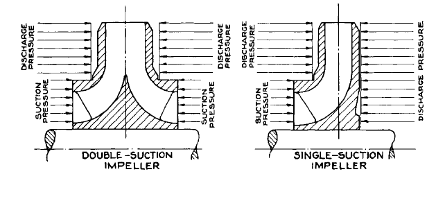
units.Theoretically, a double-suction impeller is in hydraulic axial balance, with the pres-
sures on one side equal to and counterbalancing the pressures on the other (see Figure 53).
In practice, this balance may not be achieved for the following reasons:
1. The suction passages to the two suction eyes may not provide equal or uniform flows
to the two sides.
2. External conditions, such as an elbow located too close to the pump suction nozzle,
may cause unequal flow to the two suction eyes.
FIGURE 53 The origin of pressures acting on impeller shrouds to produce an axial thrust

2.2.1 CENTRIFUGAL PUMP: MAJOR COMPONENTS 2.125
3. The two sides of the discharge casing waterways may not be symmetrical, or the
impeller may be located off-center. These conditions will alter the flow characteristics
between the impeller shrouds and the casing, causing unequal pressures on the shrouds.
4. Unequal leakage through the two leakage joints can upset the balance.
Combined, these factors can create an axial unbalance. To compensate for this, all cen-
trifugal pumps, even those with double-suction impellers, incorporate thrust bearings.
The ordinary single-suction, closed, radial-flow impeller with the shaft passing through
the impeller eye (refer to Figure 53) is subject to an axial thrust because a portion of the
front wall is exposed to suction pressure and thus relatively more backwall surface is
exposed to discharge pressure. If the discharge chamber pressure is uniform over the
entire impeller surface, the axial force acting toward the suction would be equal to the
product of the net pressure generated by the impeller and the unbalanced annular area.
Actually, pressure on the two single-suction, closed impeller walls is not uniform. The
liquid trapped between the impeller shrouds and casing walls is in rotation, and the pres-
sure at the impeller periphery is appreciably higher than the impeller hub. Although we
need not be concerned with the theoretical calculations for this pressure variation, Figure
54 describes it qualitatively. Generally speaking, the axial thrust toward the impeller suc-
tion may be about 20 to 30 percent less than the product of the net pressure and the unbal-
anced area.
To eliminate the axial thrust of a single-suction impeller, a pump can be provided with
both front and back wearing rings. To equalize the thrust areas, the inner diameter of both
rings is made the same (see Figure 55). Pressure approximately equal to the suction pres-
sure is maintained in a chamber located on the impeller side of the back wearing ring by
FIGURE 54 Pressure distribution on the front and back shrouds of the single-suction impeller with a shaft
through the impeller eye
FIGURE 55 Balancing the axial thrust of a single-suction impeller by means of wearing rings on the back side
and balancing holes

2.126 CHAPTER TWO
FIGURE 56 Pump-out vanes used in a single-suction impeller to reduce axial thrust
drilling balancing holes through the impeller. Leakage past the back wearing ring is
returned to the suction area through these holes. However, with large single-stage, single-
suction pumps, balancing holes are considered undesirable because leakage back to the
impeller suction opposes the main flow, creating disturbances. In such pumps, a piped con-
nection to the pump suction replaces the balancing holes.
Another way to eliminate or reduce an axial thrust in single-suction impellers is to use
pump-out vanes on the back shroud.The effect of these vanes is to reduce the pressure act-
ing on the back shroud of the impeller (see Figure 56). This design, however, is generally
used only in pumps handling dirty liquids where it keeps the clearance space between the
impeller back shroud and the casing free of foreign matter.
So far, our discussion of axial thrust has been limited to single-suction, closed impellers
with a shaft passing through the impeller eye that are located in pumps with two seal
chambers, one on either side of the impeller. In these pumps, suction-pressure magnitude
does not affect the resulting axial thrust.
On the other hand, axial forces acting on an overhung impeller with a single seal cham-
ber (see Figure 57) are definitely affected by suction pressure. In addition to the unbal-
anced force found in a single-suction, two-seal chamber design (refer to Figure 54), there
is an axial force equivalent to the product of the shaft area through the seal chamber and
the difference between suction and atmospheric pressure. This force acts toward the
impeller suction when the suction pressure is less than atmospheric or in the opposite
direction when it is higher than atmospheric.
When an overhung impeller pump handles a suction lift, the additional axial force is
very low. For example, if the shaft diameter through the stuffing box is 2 in (50.8 mm)
FIGURE 57 An axial thrust problem with a single-suction, overhung impeller and a single stuffing box or seal
chamber
2.2.1 CENTRIFUGAL PUMP: MAJOR COMPONENTS 2.127
(area 3.14 in
2
or 20.26 cm
2
), and if the suction lift is 20 ft (6.1 m) of water equivalent to
an absolute pressure of 6.06 lb/in
2
(0.42 bar abs), the axial force caused by the overhung
impeller and acting toward the suction will be only 27 lb (121 N). On the other hand, if the
suction pressure is 100 lb/in
2
(6.89 bar), the force will be 314 lb (1405 N) and will act in the
opposite direction. Therefore, because the same pump may be used under many conditions
over a wide range of suction pressures, the thrust bearing of pumps with single-suction,
overhung impellers must be arranged to take the thrust in either direction. They must
also be selected with a sufficient thrust capacity to counteract forces set up under the max-
imum suction pressure established for that particular pump.
This extra thrust capacity can become quite significant in certain special cases, such as
with boiler circulating pumps. These are usually of the single-suction, single-stage, over-
hung impeller type and may be exposed to suction pressures as high as 2800 lb/in
2
gage
(193 bar). This is approximately the vapor pressure of 685°F (363°C) boiler water. If such
a pump has a shaft diameter of 6-in (15.24 cm), the unbalanced thrust would be as much
as 77,500 lb (346,770 N), and the thrust bearing has to be capable of counteracting this.
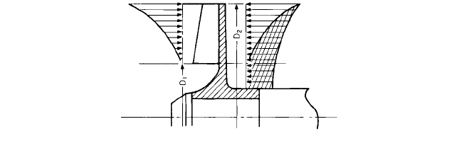
Axial Thrust of Single-Suction Semiopen Radial-Flow Impellers The axial thrust
generated in semiopen impellers is higher than that in closed impellers. This is illustrated
in Figure 58, which shows that the pressure on the open side of the impeller varies from
essentially the discharge pressure at the periphery (at diameter D
2
) to the suction pres-
sure at the impeller eye (at diameter D
1
). The pressure distribution on the back shroud
is essentially the same as that illustrated in Figure 54, varying from discharge pressure
at the periphery to some portion of this pressure at the impeller hub. This latter pressure
is, of course, substantially higher than the suction pressure. The unbalanced portion of
the axial thrust on the impeller is represented by the cross-hatched area in Figure 58.
One of the means available for partially balancing this increased axial thrust is to pro-
vide the back shroud with pump-out vanes, as in Figures 37 and 56.
Fully open impellers or semiopen impellers with a portion of the back shroud removed
produce an axial thrust somewhat higher than closed impellers and somewhat lower than
semiopen impellers.
Axial Thrust of Mixed-Flow and AxiaL-Flow Impellers The axial thrust in radial im-
pellers is produced by the static pressures on the impeller shrouds. Axial-flow impellers
have no shrouds, and the axial thrust is created strictly by the difference in pressure on
the two faces of the impeller vanes. In addition, a difference may exist in pressure acting
on the two shaft hub ends, one generally subject to discharge pressure and the other to
suction pressure.
With mixed-flow impellers, axial thrust is a combination of forces caused by the action
of the vanes on the liquid and those arising from the difference in the pressures acting on
the various surfaces.Wearing rings are often provided on the back of mixed-flow impellers,
with either balancing holes through the impeller hub or an external balancing pipe lead-
ing back to the suction.
FIGURE 58 Axial thrust in a semiopen single-suction impeller
2.128 CHAPTER TWO
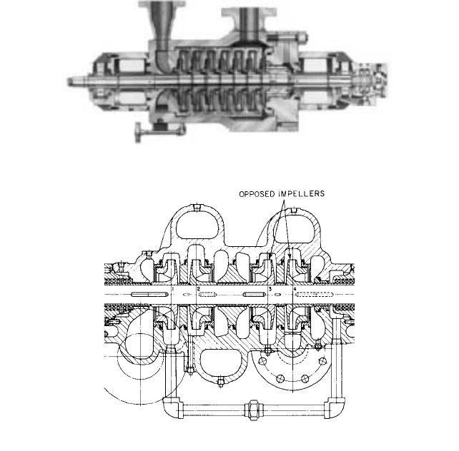
FIGURE 59 Multistage pump with single-suction impellers facing in one direction and hydraulic balancing
device (Flowserve Corporation)
Except for very large units and in certain special applications, the axial thrust devel-
oped by mixed-flow and axial-flow impellers is carried by thrust bearings with the neces-
sary load capacity.
Axial-Thrust in Multistage Pumps Most multistage pumps are built with single-suction
impellers in order to simplify the design of the interstage connections.Two obvious arrange-
ments are possible for the single-suction impellers:
1. Several single-suction impellers can be mounted on one shaft, each having its suction
inlet facing in the same direction and its stages following one another in ascending
order of pressure (see Figure 59). The axial thrust is then balanced by a hydraulic
balancing device.
2. An even number of single-suction impellers can be used, one-half facing in one
direction and the other half facing in the opposite direction. With this arrangement,
an axial thrust on the first half is compensated by the thrust in the opposite direction
on the other half (see Figure 60). This mounting of single-suction impellers back to
back is frequently called opposed impellers.
An uneven number of single-suction impellers can be used with this arrangement, pro-
vided the correct shaft and interstage bushing diameters are used to give the effect of a
hydraulic balancing device that will compensate for the hydraulic thrust on one of the stages.
FIGURE 60 A four-stage pump with opposed impellers (Flowserve Corporation)
2.2.1 CENTRIFUGAL PUMP: MAJOR COMPONENTS 2.129
It is important to note that the opposed impeller arrangement completely balances an
axial thrust only under the following conditions:
• The pump must be provided with two seal chambers.
• The shaft must have a constant diameter.
• The impeller hubs must not extend through the interstage portion of the casing
separating adjacent stages.
Except for some special pumps that have an internal and enclosed bearing at one end,
and therefore only one seal chamber, most multistage pumps fulfill the first condition.
Because of structural requirements, however, the last two conditions are not practical. A
slight residual thrust is usually present in multistage opposed impeller pumps and is car-
ried on the thrust bearing.
HYDRAULIC BALANCING DEVICES _____________________________________
If all the single-suction impellers of a multistage pump face the same direction, the total
theoretical hydraulic axial thrust acting toward the suction end of the pump will be the
sum of the individual impeller thrusts.The thrust magnitude will be approximately equal
to the product of the net pump pressure and the annular unbalanced area. Actually, the
axial thrust turns out to be about 70 to 80 percent of this theoretical value.
Some form of hydraulic balancing device must be used to balance this axial thrust and
to reduce the pressure on the seal chamber adjacent to the last-stage impeller. This
hydraulic balancing device may be a balancing drum, a balancing disk, or a combination
of the two.
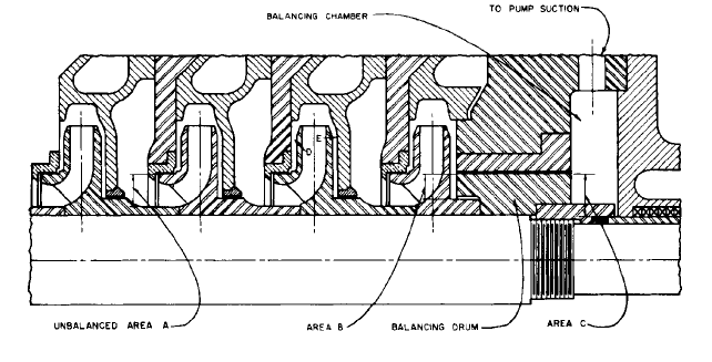
Balancing Drums The balancing drum is illustrated in Figure 61.The balancing cham-
ber at the back of the last-stage impeller is separated from the pump interior by a drum
that is usually keyed to the shaft and rotates with it. The drum is separated by a small
radial clearance from the stationary portion of the balancing device, called the balancing-
drum head, or balancing sleeve, which is fixed to the pump casing.
The balancing chamber is connected either to the pump suction or to the vessel from
which the pump takes its suction. Thus, the back pressure in the balancing chamber is
only slightly higher than the suction pressure, the difference between the two being equal
to the friction losses between this chamber and the point of return. The leakage between
FIGURE 61 Balancing drum
2.130 CHAPTER TWO
the drum and the drum head is, of course, a function of the differential pressure across the
drum and of the clearance area.
The forces acting on the balancing drum in Figure 61 are the following:
• Toward the discharge end: the discharge pressure multiplied by the front balancing area
(area B) of the drum
• Toward the suction end: the back pressure in the balancing chamber multiplied by the
back balancing area (area C) of the drum
The first force is greater than the second, thereby counterbalancing the axial thrust
exerted upon the single-suction impellers. The drum diameter can be selected to balance
the axial thrust completely or within 90 to 95 percent, depending on the desirability of car-
rying any thrust-bearing loads.
It has been assumed in the preceding simplified description that the pressure acting
on the impeller walls is constant over their entire surface and that the axial thrust is
equal to the product of the total net pressure generated and the unbalanced area. Actu-
ally, this pressure varies somewhat in the radial direction because of the centrifugal
force exerted upon the liquid by the outer impeller shroud (refer to Figure 54). Fur-
thermore, the pressures at two corresponding points on the opposite impeller faces (D
and E in Figure 61) may not be equal because of a variation in clearance between the
impeller wall and the casing section separating successive stages. Finally, a pressure
distribution over the impeller wall surface may vary with head and capacity operating
conditions.
This pressure distribution and design data can be determined quite accurately for
any one fixed operating condition, and an effective balancing drum could be designed
on the basis of the forces resulting from this pressure distribution. Unfortunately,
varying head and capacity conditions change the pressure distribution, and as the
area of the balancing drum is necessarily fixed, the equilibrium of the axial forces can
be destroyed.
The objection to this is not primarily the amount of the thrust, but rather that the
direction of the thrust cannot be predetermined because of the uncertainty about internal
pressures. Still it is advisable to predetermine normal thrust direction, as this can influ-
ence external mechanical thrust-bearing design. Because 100 percent balance is unat-
tainable in practice and because the slight but predictable unbalance can be carried on a
thrust bearing, the balancing drum is often designed to balance only 90 to 95 percent of
the total impeller thrust.
The balancing drum satisfactorily balances the axial thrust of single-suction impellers
and reduces pressure on the discharge-side stuffing box. It lacks, however, the virtue of
automatic compensation for any changes in axial thrust caused by varying impeller reac-
tion characteristics. In effect, if the axial thrust and balancing drum forces become
unequal, the rotating element will tend to move in the direction of the greater force. The
thrust bearing must then prevent excessive movement of the rotating element. The bal-
ancing drum performs no restoring function until such time as the drum force again
equals the axial thrust. This automatic compensation is the major feature that differenti-
ates the balancing disk from the balancing drum.
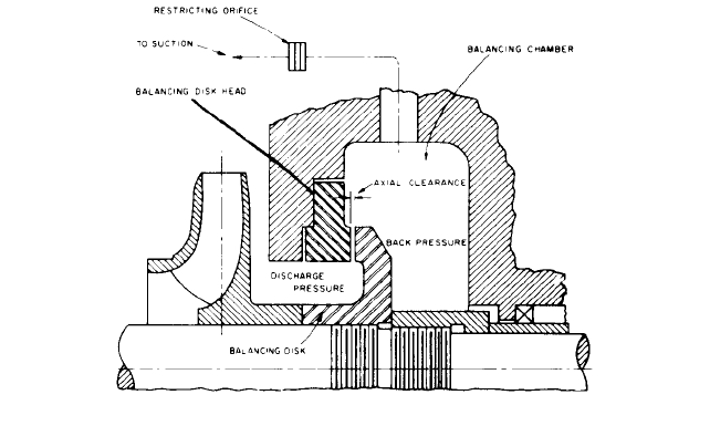
Balancing Disks The operation of the simple balancing disk is illustrated in Figure 62.
The disk is fixed to and rotates with the shaft. It is separated by a small axial clearance
from the balancing disk head, or balancing sleeve, which is fixed to the casing. The leak-
age through this clearance flows into the balancing chamber and from there either to the
pump suction or to the vessel from which the pump takes its suction. The back of the bal-
ancing disk is subject to the balancing chamber back pressure, whereas the disk face expe-
riences a range of pressures. These vary from discharge pressure at its smallest diameter
to back pressure at its periphery. The inner and outer disk diameters are chosen so that
the difference between the total force acting on the disk face and that acting on its back
will balance the impeller axial thrust.
If the axial thrust of the impellers should exceed the thrust acting on the disk during
operation, the latter is moved toward the disk head, reducing the axial clearance between
2.2.1 CENTRIFUGAL PUMP: MAJOR COMPONENTS 2.131
FIGURE 62 A simple balancing disk
the disk and the disk head. The amount of leakage through the clearance is reduced so
that the friction losses in the leakage return line are also reduced, lowering the back pres-
sure in the balancing chamber. This lowering of pressure automatically increases the pres-
sure difference acting on the disk and moves it away from the disk head, increasing the
clearance. Now the pressure builds up in the balancing chamber, and the disk is again
moved toward the disk head until an equilibrium is reached.
To assure proper balancing in disk operation, the change in back pressure in the bal-
ancing chamber must be of an appreciable magnitude.Thus, with the balancing disk wide
open with respect to the disk head, the back pressure must be substantially higher than
the suction pressure to give a resultant force that restores the normal disk position. This
can be accomplished by introducing a restricting orifice in the leakage return line that
increases back pressure when leakage past the disk increases beyond normal. The disad-
vantage of this arrangement is that the pressure on the seal chamber is variable, a condi-
tion that may be injurious to the life of the seal and therefore should avoided.
Combination Balancing Disk and Drum For the reasons just described, the simple
balancing disk is seldom used. The combination balancing disk and drum (see Figure 63)
was developed to obviate the shortcomings of the disk while retaining the advantage of
automatic compensation for axial thrust changes.
The rotating portion of this balancing device consists of a long cylindrical body that
turns within a drum portion of the disk head. This rotating part incorporates a disk simi-
lar to the one previously described. In this design, radial clearance remains constant
regardless of disk position, whereas the axial clearance varies with the pump rotor posi-
tion. The following forces act on this device:
• Toward the discharge end: the sum of the discharge pressure multiplied by area A, plus
the average intermediate pressure multiplied by area B
• Toward the suction end: the back pressure multiplied by area C
Whereas the position-restoring feature of the simple balancing disk required an unde-
sirably wide variation of the back pressure, it is now possible to depend upon a variation
of the intermediate pressure to achieve the same effect. Here is how it works: When the
pump rotor moves toward the suction end (to the left in Figure 63) because of increased
axial thrust, the axial clearance is reduced and pressure builds up in the intermediate