Pump Handbook by Igor J. Karassik, Joseph P. Messina, Paul Cooper, Charles C. Heald - 3rd edition
Подождите немного. Документ загружается.

2.152 CHAPTER TWO
FIGURE 89 Single-row, angular contact bearing
(SKF USA, Inc.)
FIGURE 90 Double-row, angular-contact bearing
(SKF USA, Inc.)
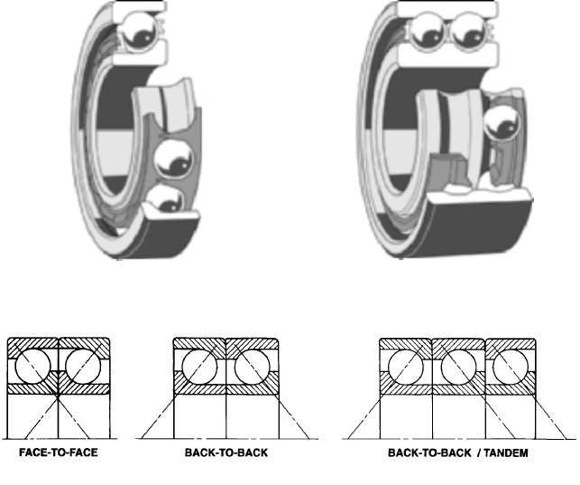
FIGURE 91 Paired bearing arrangements (SKF USA, Inc.)
reversing direction. When this occurs, a typical back-to-back angular contact bearing
arrangement can result in one bearing becoming nearly completely unloaded. In the most
severe cases of axial unloading of angular contact bearings, skidding of the unloaded balls
within the bearing races can occur. This skidding can result in bearing heating and sub-
sequent damage, even failure, with time.To avoid ball skidding under light load or no-load
conditions, standard angular contact bearing sets can be arranged for a light preload that
will result in a sufficient load on the dynamically unloaded bearing to prevent skidding.
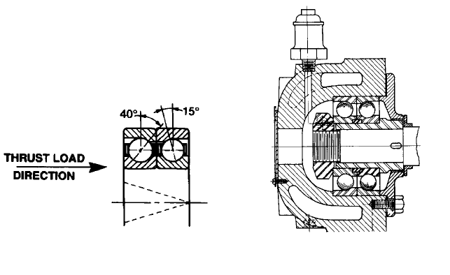
Another alternative is to install a matched set of two angular contact bearings with dif-
ferent contact angles (see Figure 92). By utilizing an angular contact bearing with a lower
contact angle (say 15 degrees instead of the normal 40 degrees), the unloaded bearing will
have a lower requirement for an axial load and be more resistant to ball skidding. This
means the bearing will run at a lower temperature.
The double-row, angular contact ball bearing (see Figure 93) is similar in design to a
back-to-back pair of single-row, angular contact ball bearings, but in a narrower width
package. Its ease of mounting, along with its low-friction operation, high-speed capability,
and seal or shield availability, make it an ideal bearing for light- to medium-duty end suc-
tion centrifugal pumps and submersible pumps.
Lubrication of Antifriction Bearing In the layout of a line of centrifugal pumps, the
choice of the lubricant for the pump bearings is dictated by application requirements, by
cost considerations, and sometimes by the preferences of a group of purchasers commit-
ted to the major portion of the output of that line. For example, in vertical wet-pit con-
denser circulating pumps, water is the lubricant of choice, in preference to grease or oil.
If oil or grease is used in such pumps and the lubricant leaks into the pumping system,
the condenser operation might be seriously affected because the tubes would become
coated with the lubricant.
2.2.1 CENTRIFUGAL PUMP: MAJOR COMPONENTS 2.153
FIGURE 92 Angular contact bearings with
different contact angles (SKA USA, Inc.)
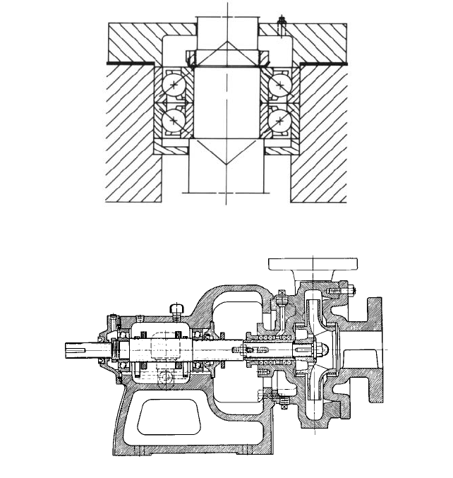
FIGURE 93 A double-row, angular-contact ball
thrust bearing that is grease-lubricated and water-
cooled
Most centrifugal pumps for refinery services are supplied with oil-lubricated bearings
because of the insistence of refinery engineers on this feature. In the marine field, on the
other hand, the preference lies with grease-lubricated bearings. For high pump operating
speeds (5,000 rpm and above), oil lubrication is found to be the most satisfactory. For
highly competitive lines of small pumps, the main consideration is cost, and so the most
economical lubricant is chosen, depending upon the type of bearing used.
Ball bearings used in small centrifugal pumps are usually grease-lubricated, although
some services use oil lubrication. In grease-lubricated bearings, the grease packed into the
bearing is thrown out by the rotation of the balls, creating a slight suction at the inner
race. (Even if the grade of grease is relatively light, it is still a semisolid and flows slowly.
As heat is generated in the bearing, however, the flow of the grease is accelerated until the
grease is thrown out at the outer race by the rotation.) As the expelled grease is cooled by
contact with the housing and thus is attracted to the inner race, a continuous circulation
of grease lubricates and cools the bearing.This method of lubrication requires a minimum
amount of attention and has proved itself very satisfactory. A vertically mounted thrust
bearing arranged for grease lubrication is shown in Figure 94.
A bearing fully packed with grease prevents proper grease circulation in itself and its
housing. Therefore, as a general rule, it is recommended that only one-third of the void
spaces in the housing be filled. An excess amount of grease will cause the bearing to heat
up, and grease will flow out of the seals to relieve the situation. Unless the excess grease
can escape through the seal or through the relief cock that is used on many large units, the
bearing will probably fail early.
In oil-lubricated ball bearings, a suitable oil level must be maintained in the housing.
This level should be at about the center of the lowermost ball of a stationary bearing. It
can be achieved by a dam and an oil slinger to maintain the level behind the dam and
thereby increase the leeway in the amount of oil the operator must keep in the housing.
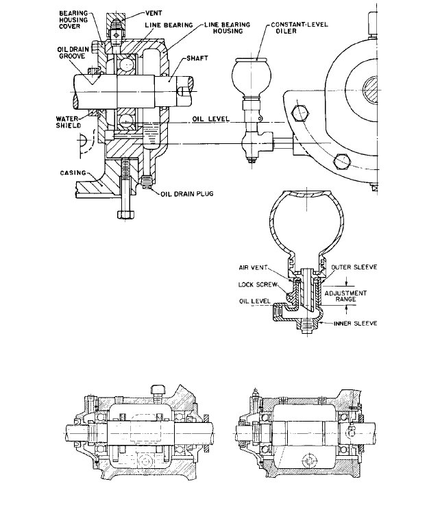
Oil rings are sometimes used to supply oil to the bearings from the bearing housing reser-
voir (see Figure 95). In other designs, a constant-level oiler is used (see Figure 96).
Because of the advantages of interchangeability, some pump lines are built with bear-
ing housings that can be adapted to either oil or grease lubrication with minimum modi-
fications (see Figure 97).
Oil Film or Sleeve Bearings See Subsection 2.2.5.
2.154 CHAPTER TWO
FIGURE 94 Vertically mounted thrust bearing arranged for grease lubrication (SKF USA, Inc.)
FIGURE 95 A ball bearing pump with oil rings
COUPLINGS_________________________________________________________
Centrifugal pumps are connected to their drivers through couplings of one sort or another,
except for close-coupled units, in which the impeller is mounted on an extension of the
shaft of the driver.
Because couplings can be used with both centrifugal and positive displacement pumps,
they are discussed separately in Section 6.3.
BEDPLATE AND OTHER PUMP SUPPORTS_______________________________
For very obvious reasons, it is desirable that pumps and their drivers be removable from
their mountings. Consequently, they are usually bolted and doweled to machined surfaces
that in turn are firmly connected to a foundation. To simplify the installation of horizon-
tal-shaft units, these machined surfaces are usually part of a common bedplate on which
either the pump or the pump and its driver have been prealigned.
2.2.1 CENTRIFUGAL PUMP: MAJOR COMPONENTS 2.155
FIGURE 96 A constant-level oiler
FIGURE 97 Ball bearings arranged (left) with oil rings in the housing and (right) for grease lubrication
Bedplates The primary function of a pump bedplate is to furnish mounting surfaces for
the pump feet that can be rigidly attached to the foundation. Mounting surfaces are also
necessary for the feet of the pump driver or drivers and for the feet of any independently
mounted power transmission device. Although such surfaces could be provided by sepa-
rate bedplates or by individually planned surfaces, it would be necessary to align these
separate surfaces and fasten them to the foundation with the utmost care. Usually, this
method requires in-place mounting in the field as well as drilling and tapping for the bolts
after all the parts have been aligned.To minimize such field work, coupled horizontal-shaft
pumps are usually purchased with a continuous base extending under the pump and its
driver. Ordinarily, both these units are mounted and aligned at the place of manufacture.
Although such bases are designed to be quite rigid, they deflect if improperly sup-
ported. It is therefore necessary to support them on a foundation that can supply the
required rigidity. Furthermore, as the base can be sprung out of shape by improper han-
dling during transit, it is imperative that the alignment be carefully rechecked during
erection and prior to starting the unit.
2.156 CHAPTER TWO
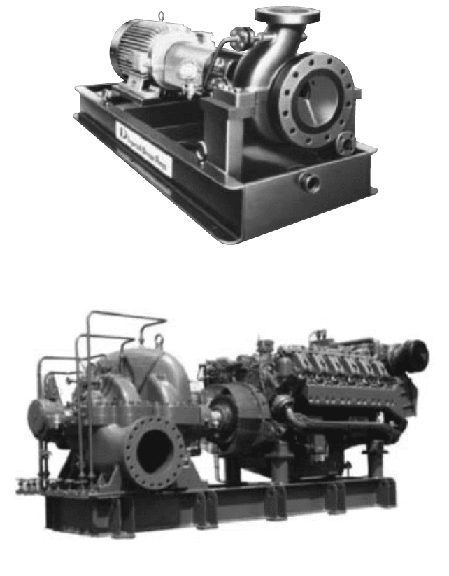
FIGURE 98 Horizontal shaft overhung pump and driver on a structural steel bedplate with a raised edge around
the base and a tapped drainage connection (Flowserve Corporation)
As the unit size increases, so does the size, weight, and cost of the base required. The
cost of a prealigned base for most large units exceeds the cost of the field work necessary
to align individual bedplates or soleplates and to mount the component parts. Such bases
are therefore used only if appearances require them or if their function as a drip collector
justifies the additional cost. Even in fairly small units, the height at which the feet of the
pump and the other elements are located may differ considerably. A more rigid and nice-
looking installation can frequently be obtained by using individual bases or soleplates and
building up the foundation to various heights under the separate portions of equipment.
Baseplates are usually provided with a raised edge or raised lip around the base to pre-
vent dripping or draining onto the floor (see Figure 98). The base itself is sloped toward
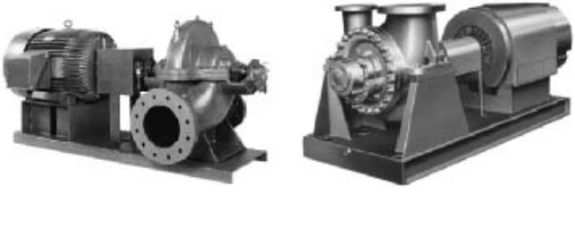
FIGURE 99 Horizontal shaft centrifugal pump and internal combustion engine mounted on a structural steel
bedplate (Flowserve Corporation)
2.2.1 CENTRIFUGAL PUMP: MAJOR COMPONENTS 2.157
FIGURE 100 Horizontal shaft centrifugal pump and
driver on a structural steel bedplate made of a simple
channel shape (Flowserve Corporation)
FIGURE 101 Single-stage double-suction pump with
centerline support (Flowserve Corporation)
one end to collect the drainage for further disposal. A drain pocket is provided near the bot-
tom of the slope, sometimes with a mesh screen. A tapped connection in the pocket permits
piping the drainage to a convenient point.
Bedplates are usually fabricated from steel plate and structural steel shapes (see Fig-
ures 99 and 100). Even though most of these fabrications have a drain capability, because
of the popular use of mechanical seals and the containment of stuffing box leakage for
pumps that continue to use shaft packing (leakage is usually collected in the bearing
bracket and piped to a common collecting point), the bedplate surfaces actually are seldom
used to collect leakage from the pumping equipment during operation. Bedplate drain sur-
faces are usually employed to contain the leakage of pumpage and other liquids during
pump maintenance and removal or in the event of a seal or packing failure.
Soleplates Soleplates are cast-iron or steel pads located under the feet of the pump or its
driver and are embedded in the foundation. The pump or its driver is doweled and bolted
to them. Soleplates are customarily used for vertical dry-pit pumps and also for some of the
larger horizontal units to save the cost of the large bedplates otherwise required.
Centerline Support For operation at high temperatures, the pump casing must be sup-
ported as near to its horizontal centerline as possible in order to prevent excessive strains
caused by temperature differences. Such strains might seriously disturb the alignment of
the unit and eventually damage it. Centerline construction is usually employed in boiler-
feed, refinery, and hot-water circulating pumps (see Figure 101). The exact temperature
at which centerline support construction becomes mandatory varies from 250 to 350°F
(121 to 177°C).
Horizontal Units Using Flexible Pipe Connections The previous discussion of bed-
plates and supports for horizontal-shaft units assumed their application would be to
pumps with piping setups that do not impose hydraulic thrusts on the pumps. If flexible
pipe connections or expansion joints are desirable in the suction or discharge piping of a
pump (or in both), the pump manufacturer should be so advised for several reasons. First,
the pump casing will be required to withstand various stresses caused by the resultant
hydraulic thrust load. Although this is rarely a limiting or dangerous factor, it is best that
the manufacturer have the opportunity to check the strength of the pump casing. Second,
the resulting hydraulic thrust has to be transmitted from the pump casing through the
casing feet to the bedplate or soleplate and then to the foundation. Usually, horizontal-
shaft pumps are merely bolted to their bases or soleplates, and so any tendency to dis-
placement is resisted only by the frictional grip of the casing feet on the base and by
relatively small dowels. If flexible pipe joints are used, this attachment may not be suffi-
cient to withstand the hydraulic thrust. If high hydraulic thrust loads are to be encoun-
tered, therefore the pump feet must be keyed to the base or supports. Similarly, the
2.158 CHAPTER TWO
bedplate or supporting soleplates must be of a design that will permit transmission of the
load to the foundation. Each of these design elements must be checked to confirm their
capability to withstand hyraulic thrust loads from flexible pipe connections. Preferably
expansion joints will be restrained to avoid transmitting loads to the pump nozzles.
VERTICAL PUMPS____________________________________________________
Vertical-shaft pumps fall into two classifications: dry-pit and wet-pit. Dry-pit pumps are
surrounded by air, and the wet-pit types are either fully or partially submerged in the liq-
uid handled.
Vertical Dry-Pit Pumps Dry-pit pumps with external bearings include most small,
medium, and large vertical sewage pumps, most medium and large drainage and irriga-
tion pumps for medium and high heads, many large condenser circulating and water sup-
ply pumps, and many marine pumps. Sometimes the vertical design is preferred
(especially for marine pumps) because it saves floor space. At other times, it is desirable
to mount a pump at a low elevation because of suction conditions, and it is then also
preferable or necessary to have the pump driver at a high elevation. The vertical pump is
normally used for large capacity applications because it is more economical than the hor-
izontal type, all factors considered.
Many vertical dry-pit pumps are basically horizontal designs with minor modifications
(usually in the bearings) to adapt them for vertical-shaft drive. This is not true of small-
and medium-sized sewage pumps, however. In these units, a purely vertical design is the
most popular. Most of these sewage pumps have elbow suction nozzles (see Figures 102
through 104) because their suction supply is usually taken from a wet well adjacent to the
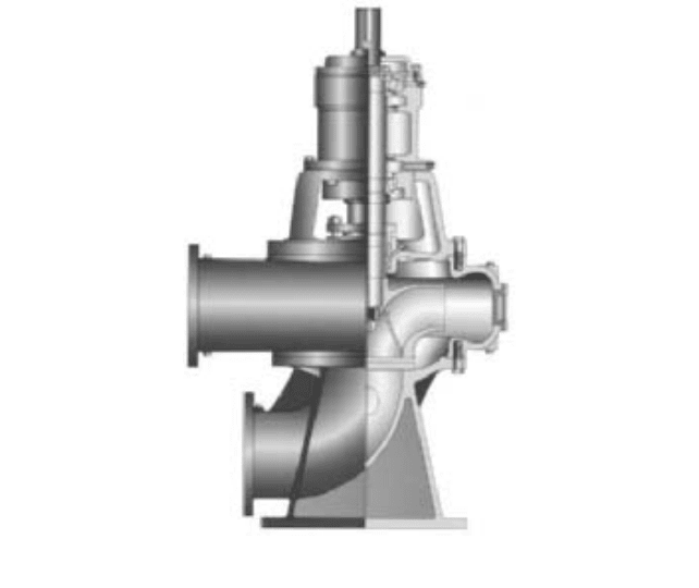
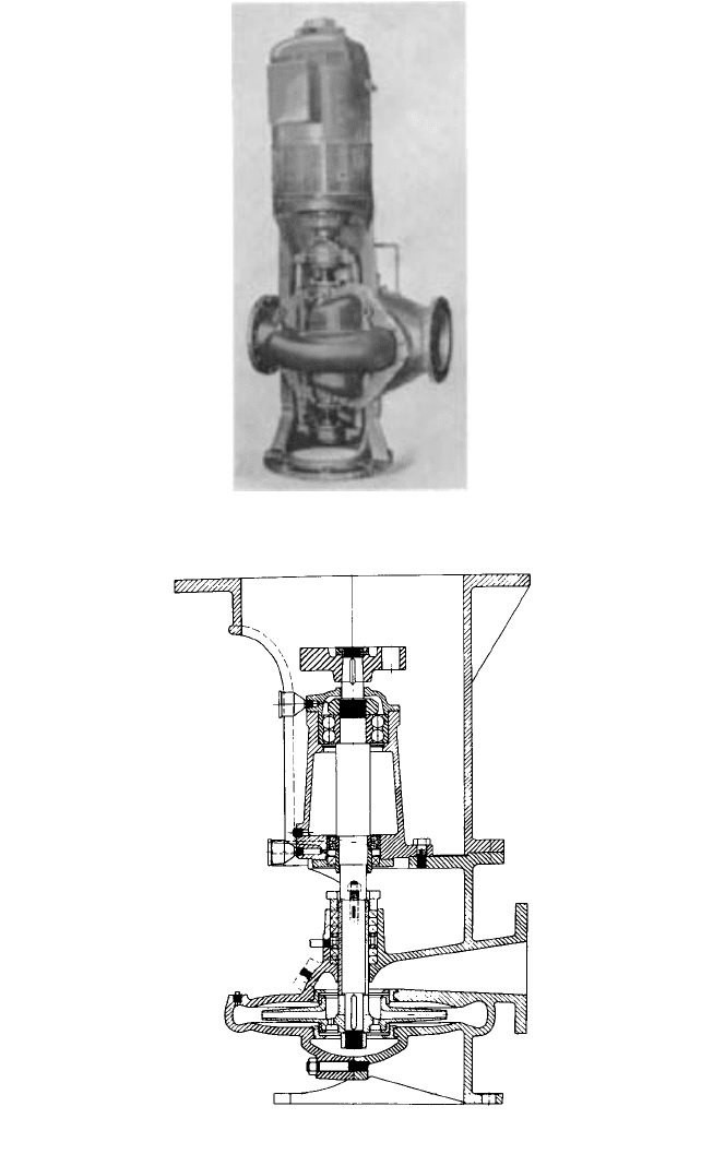
FIGURE 102 Section of a vertical sewage pump with end-suction (elbow) and side discharge (Flowserve
Corporation)
2.2.1 CENTRIFUGAL PUMP: MAJOR COMPONENTS 2.159
FIGURE 103 An installed vertical sewage pump similar to that shown in Figure 102 (Flowserve Corporation)
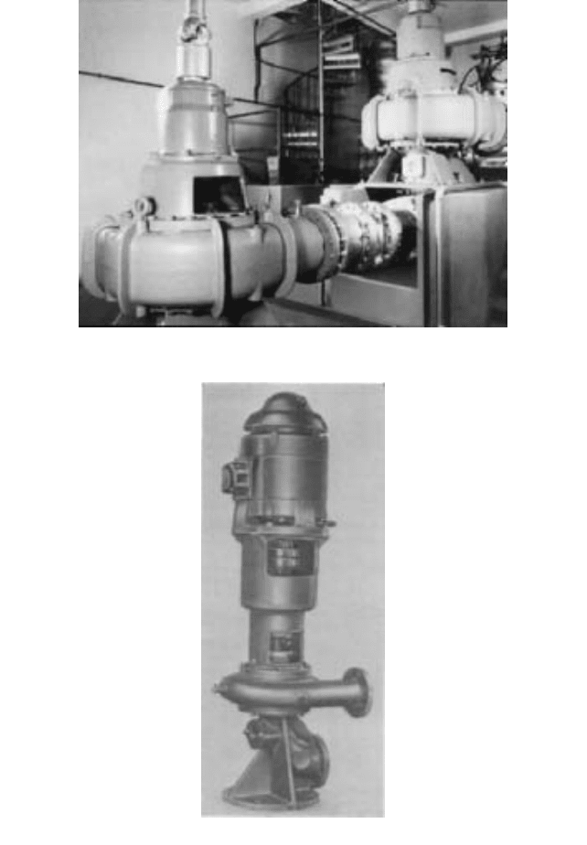
FIGURE 104 Vertical sewage pump with a direct-mounted motor (Flowserve Corporation)
pit in which the pump is installed. The suction elbow usually contains a handhole with a
removable cover to provide easy access to the impeller.
To dismantle one of these pumps, the stuffing box head must be unbolted from the cas-
ing after the intermediate shaft or the motor and motor stand have been removed. The
rotor assembly is drawn out upward, complete with the stuffing box head, the bearing
2.160 CHAPTER TWO
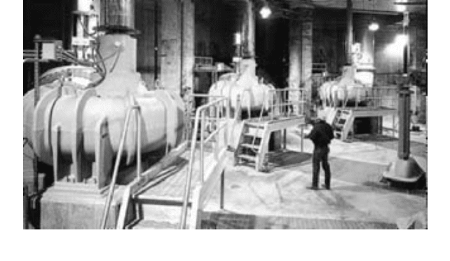
FIGURE 105 Vertical bottom-suction volute pumps installed in a sewage pumping station (Flowserve
Corporation)
housing, and the like. This rotor assembly can then be completely dismantled at a conve-
nient location.
Vertical-shaft installations of single-suction pumps with a suction elbow are commonly
furnished with either a pedestal or a base elbow (refer to Figure 102), both of which can
be bolted to soleplates or even grouted in. The grouting arrangement is not desirable
unless there is full assurance that the pedestal or elbow will never be disturbed or that the
grouted space is reasonably regular and the grout will separate from the pump without
excessive difficulty.
Vertical single-suction pumps with bottom suction are commonly used for larger
sewage, water supply, or condenser circulating applications. Such pumps are provided with
wing feet that are bolted to soleplates grouted in concrete pedestals or piers (see Figure
105). Sometimes the wing feet may be grouted right in the pedestals. These must be suit-
ably arranged to provide proper access to any handholes in the pump and to allow clear-
ance for the elbow suction nozzles if these are used.
If a vertical pump is applied to a condensate service or some other service for which the
eye of the impeller must be vented to prevent vapor binding, a pump with a bottom single-
inlet impeller is not desirable because it does not permit effective venting. Neither does a
vertical pump employing a double-suction impeller (see Figure 106). The most suitable
design for such applications incorporates a top single-inlet impeller (see Figure 107).
If the driver of a vertical dry-pit pump can be located immediately above the pump, it
is often supported on the pump itself (refer to Figure 104).The shafts of the pump and dri-
ver may be connected by a flexible coupling, which requires that each have its own thrust
bearing. If the pump shaft is rigidly coupled to the driver shaft or is an extension of the dri-
ver shaft, a common thrust bearing is used, normally in the driver.
Although the driving motors are frequently mounted on top of the pump casing, one
important reason for the use of the vertical shaft design is the possibility of locating the
motors at an elevation sufficiently above the pumps to prevent the accidental flooding of
the motors. The pump and its driver may be separated by an appreciable length of shaft-
ing, which may require steady bearings between the two units. Subsection 6.3.1 discusses
the construction and arrangement of the shafting used to connect vertical pumps to dri-
vers located some distance above the pump elevation.
Bearings for vertical dry-pit pumps and for intermediate guide bearings are usually
antifriction grease-lubricated types to simplify the problem of retaining a lubricant in a
housing with a shaft projecting vertically through it. Larger units, for which antifriction
bearings are not available or desirable, use self-oiling, babbitt steady bearings with spiral
2.2.1 CENTRIFUGAL PUMP: MAJOR COMPONENTS 2.161
FIGURE 106 A vertical double-suction volute pump with a direct-mounted motor (Flowserve Corporation)
FIGURE 107 A section of a vertical pump with a top-suction inlet impeller (Flowserve Corporation)