Pump Handbook by Igor J. Karassik, Joseph P. Messina, Paul Cooper, Charles C. Heald - 3rd edition
Подождите немного. Документ загружается.

2.172 CHAPTER TWO
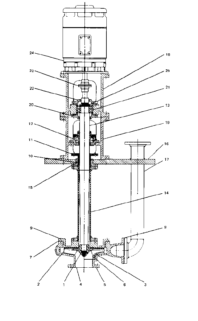
FIGURE 120 Vertical wet-pit cantilever-type volute pump: (1) impeller nut, (2) open impeller, (3) closed impeller,
(4) open casing, (5) closed casing, (6) casing wearing ring, (7) casing gasket, (8) discharge flange gasket, (9) back
cover, (10) packing or mechanical seal, (11) packing or seal gland, (12) radial bearing, (13) shaft, (14) supporting
pipe, (15) separate stuffing box, (16) sump cover, (17) discharge pipe, (18) upper motor pedestal, (19) lower motor
pedestal, (20) lower thrust bearing cover, (21) thrust bearing, (22) upper thrust bearing cover, (23) coupling, (24)
motor, (25) bearing locknut and washer (Laurence Pump)
2.2.1 CENTRIFUGAL PUMP: MAJOR COMPONENTS 2.173
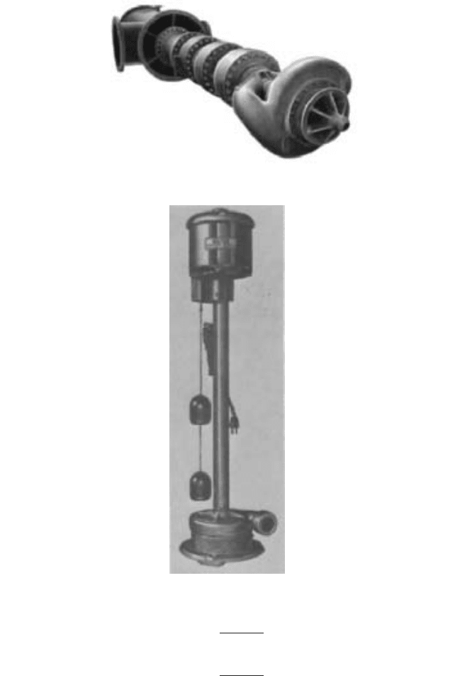
FIGURE 121 Double-suction, wet-pit pump (Flowserve Corporation)
FIGURE 122 A cellar-drainer sump pump (Sta-Rite Products)
in USCS units
in SI units
where F
u
upthrust, lb (N)
K constant related to the impeller type
V
e
velocity in the impeller eye ft/s (m/s)
F
u
KV
2
e
A
e
2g11.022
F
u
KV
2
e
A
e
2g12.312
2.174 CHAPTER TWO
FIGURE 123 A duplex sump pump (Economy Pump)
A
e
net eye area, in
2
(cm
2
)
g 32.2 ft/s
2
(9.81 m/s
2
)
The constant K is 1.0 for a fully radial-flow impeller, less than 1.0 for a mixed-flow
impeller, and essentially zero for a fully axial-flow impeller.
Under normal operating conditions, the upward thrust caused by the change of
momentum is hardly significant in comparison with the downward thrust caused by the
unbalanced pressures acting on the single-suction impeller. Consider the example of an
impeller with the following characteristics:
Capacity 2,500 gpm (568 m
3
/h)
Total head 231 ft (70.4 m)
Net pressure 100 lb/in
2
(6.89 bar)
Unbalanced eye area 40 in
2
(258 cm
2
)
If we neglect the effect of the pressure distribution on the shrouds of the impeller, the
downward thrust is
in USCS units
in SI units
The upward force caused by the change of momentum is
6.89 10
5
258
10,000
17,800 N
100 40 4000 lb
2.2.1 CENTRIFUGAL PUMP: MAJOR COMPONENTS 2.175
in USCS units
in SI units
This is certainly negligible relative to the downward hydraulic axial thrust.
The situation is quite different, however, during the startup of a vertical pump.Although
the motor may get up to full speed in just a few seconds, it takes a certain amount of time for
the total head to increase from zero that corresponding to the normal operating capacity. Con-
sequently, the pump will be operating in a very high capacity range. Since the upward force
caused by the change of momentum varies as the square of the capacity while the downward
axial thrust caused by pressure differences is very low, there can be a momentary net upward
force, or upthrust. This means that thrust bearings intended to accommodate the axial thrust
of vertical pumps must be capable of accommodating some thrust in the upward direction in
addition to the normal downward thrust. This is particularly true for pumps with relatively
low heads per stage and with short settings because in these units the rotor weight does not
at all times compensate for the upthrust from the change in momentum.
Particular care must be exercised in defining the range of vertical movement allowed
for the thrust bearings because any such movement must remain within the displacement
limits of any mechanical seal used in the pump.
In rather rare cases, a close-coupled vertical pump is operated at such a high capacity
that a continuous net upthrust is generated. Such operations can damage the pump because
the line shaft is operated in compression and may buckle, causing vibration and bearing
wear. The manufacturer’s comments should be invited if such an operation is contemplated.
Shaft Elongation in Vertical Pumps The elongation of a vertical pump shaft is caused
by three separate phenomena: (1) the tensile stress caused by the weight of the rotor, (2)
the tensile stress caused by the axial thrust, and (3) the thermal expansion of the shaft.
In most cases, the tensile stress created by the axial thrust is several times greater than
that created by the weight. In a typical example of a 16,000-gpm (3636-m
3
/h) pump designed
for a 175-ft (53.3 m) head and 50 ft (15.25 m) long, the elongation caused by the weight of a
1600-pound (726 kg) impeller will be of the order of 0.0033 in (0.084 mm). The elongation
caused by the axial thrust will be approximately 0.0315 in (0.8 mm).
The elongation caused by thermal expansion has to be considered from two angles.
First, if the shaft and the stationary parts are built of materials that have essentially the
same coefficient of expansion, both will expand equally and no significant relative elonga-
tion will take place. Second, if the pumps are operated in essentially the same range of
temperatures in which they were assembled, no significant relative expansion will take
place, even if dissimilar coefficients of expansion are involved. Whatever the case, the
pump manufacturers take these factors into consideration by providing the necessary ver-
tical end-play between the stationary and rotating pump components.
Loads on Foundations of Vertical Pumps If the motor support is integral with the
pump discharge column, as in Figures 110, 112, and 113, and if the hydraulic thrust is
carried by the motor thrust bearing, this thrust is not additive to the deadweight of the
pump and of its motor plus the weight of the water contained in the pump, insofar as the
load on the foundations is concerned. This is because the pump and motor mounted in
this fashion form a self-contained entity and all internal forces and stresses are balanced
within this entity. If the pump and motor are supported separately, however, as in Figure
124, and are joined by a rigid coupling that transmits the pump hydraulic thrust to the
motor thrust bearing, the foundations will carry the following loads when the pump is
running:
1 a
568 10,000
258 3600
b
2
258
2 9.81 1.02
481 N
1.0 a
2500 0.32
40
b
2
40
64.4 2.31
107.5 lb
2.176 CHAPTER TWO
FIGURE 124 The vertical pump and driving motor supported separately (Flowserve Corporation)
• The foundation supporting the motor: the weight of the motor plus the weight of the
pump rotor plus the axial hydraulic thrust developed by the pump
• The foundation supporting the pump: the weight of the pump stationary parts plus the
weight of the water in the pump, including the water in the discharge pipe supported
by the foundation, less the axial hydraulic thrust developed by the pump
Since when the pump is idle the foundation supporting the pump is not benefited by
the reduction in load equivalent to the axial hydraulic thrust, both running and idle oper-
ating conditions must be considered in this case.
Typical Arrangements of Vertical Pumps A pump is only part of a pumping system.
The hydraulic design of the system external to the pump will affect the overall economy
of the installation and can easily have an adverse effect upon the performance of the pump
itself. Vertical pumps are particularly susceptible because the small floor space occupied
2.2.1 CENTRIFUGAL PUMP: MAJOR COMPONENTS 2.177
by each unit offers the temptation to reduce the size of the station by placing the units
closer together. If the size is reduced, the suction arrangement may not permit the proper
flow of water to the pump suction intake. Recommended arrangements for vertical pumps
are discussed in Section 10.1.
SPECIAL PURPOSE PUMPS ___________________________________________
In addition to the more or less general purpose pumps described on the preceding pages,
literally hundreds of centrifugal pumps are intended for very specific applications.
Although it is impossible to describe every one of these special purpose designs, many of
them are discussed and illustrated in Sections 9.1 through 9.22, covering a variety of
pump services. However, several specific designs are seeing rapidly increasing usage and
so are discussed in greater detail here.
Submersible Motor-Driven Wet-Pit Pumps The installation of conventional vertical
wet-pit pumps with the motor located above the liquid level may require a considerable
length of drive shafting, particularly in the case of deep settings.The addition of this shaft-
ing, of the many line bearings, and possibly of an external lubrication system may repre-
sent a major portion of the total installed cost of the pumping unit. Furthermore, shaft
alignment becomes more critical, and shaft elongation and power losses increase rapidly
as the setting is increased, especially for deep-well pumps.
A great variety of submersible motors have been developed to obviate these shortcom-
ings. They are described in Subsection 6.1.1, and a classification of the various types of
such motors is presented in Figure 26 of that subsection. Submersible wet-pit pumps elim-
inate the need for extended shafting, shaft couplings, a mechanical seal or stuffing box, a
subsurface motor stand, and, in some cases, an expensive pump house. Both vertical tur-
bine and volute-type wet-pit pumps may be so driven.
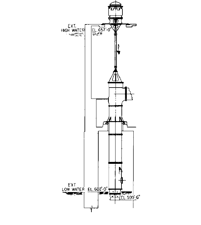
Figures 125 and 126 illustrate, respectively, the external appearance and a cross sec-
tion of a vertical turbine pump driven by a submersible motor located at the bottom of the
pump. The pump suction is through a perforated strainer located between the motor and
the first-stage impeller bowl. There is, of course, no shafting above the pump and the
pump-and-motor unit is supported by the discharge pipe only. No external lubrication is
required. The motor is completely enclosed and oil-filled and is provided with a thrust
bearing to carry the pump downthrust. A mechanical seal is provided at the motor shaft
extension, which is connected to the pump shaft with a rigid coupling. Only a discharge
elbow and the electric cable connection are seen above the surface support plate. On occa-
sion, this type of pump is used horizontally as a booster pump in a pipeline, and in such
cases the elbow at the discharge is eliminated.
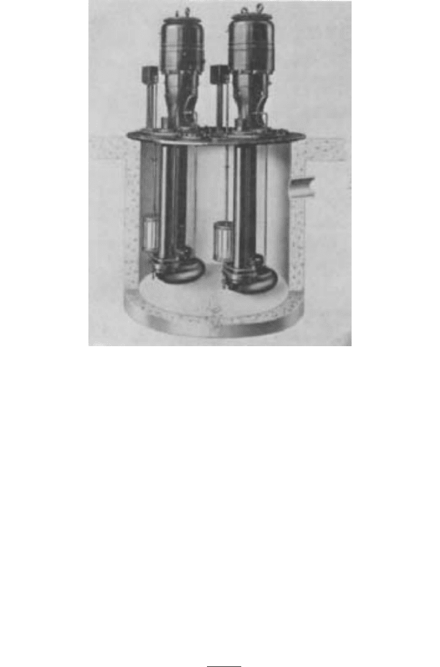
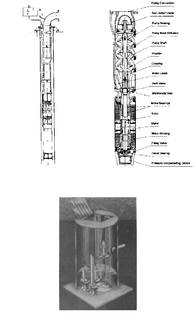
Vertical wet-pit volute-type sump pumps can be obtained with close-coupled sub-
mersible motors for drainage, sewage, process, and slurry services. Figure 127 illustrates
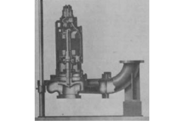
dual submersible sewage pumps in a below ground collecting tank.The pumps (see Figure
128) are supported by guide rails that make it possible to lower and raise the pumps by
means of a chain hoist. During this operation, the discharge pipe is connected and discon-
nected without dewatering the tank. Other arrangements use foot-supported pumps with
rigid discharge piping.
Motors used for this type of construction are usually hermetically sealed, employing a
double mechanically sealed oil chamber with a moisture-sensing probe to detect any influx
of conductive liquid past the outer seal. Controls to start and stop the pump motors can be
either an air compressor bubbler system or level-sensing switches that tilt when floated
(refer to Figure 127).
Small portable pumps are available with flexible discharge hoses and built-in water-
level motor control switches activated by trapped air pressure. Motors for these pumps are
usually oil-filled and have a single mechanical shaft seal but are also available in a her-
metically sealed design. The submersible motors are cooled by the liquid in which they are
immersed and therefore should not be run dewatered, although some motors can operate
for short periods (10 to 15 min.) this way.
2.178 CHAPTER TWO
FIGURE 125 Vertical turbine pump driven by a
submersible motor (Flowserve Corporation)
FIGURE 126 Cross-sectional view of a submersible
pump (Flowserve Corporation)
FIGURE 127 Dual submersible sewage pumps in a below ground collecting tank (Flowserve Corporation)
2.2.1 CENTRIFUGAL PUMP: MAJOR COMPONENTS 2.179
FIGURE 128 A section of a submersible sewage pump shown in Figure 127 (Flowserve Corporation)
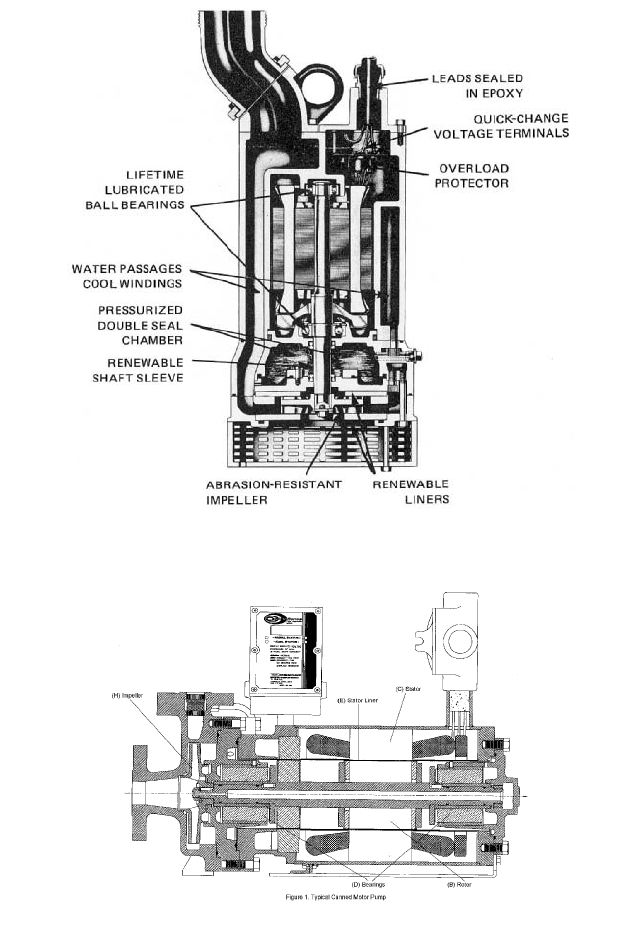
In a pump-motor combination (see Figure 129), the motor is cooled by the pumped liq-
uid as it moves through a passage around the sides of the motor. This design also uses a
pressurized oil-seal chamber to assure positive sealing.
Sealless Pumps Completely leakproof pumps are available for pumping corrosive,
volatile, radioactive, and otherwise hazardous liquids. Canned motor pumps (see Figure
130) are an assembly of a standard centrifugal pump and a squirrel-cage induction motor
in a hermetically sealed unit. Modifying a recirculating flow system in a canned motor
pump can allow it to be used in applications at up to 1000°F (538°C).
Magnetic drive pumps (see Figure 131) are an assembly of a rotor, an impeller, product
lubricated bearings, and a magnetic carrier inside an isolation shell or diaphragm. This
rotor is driven by magnets outside the shell or diaphragm. No mechanical connection
exists between the driven magnets and the driving magnets. No seals exist and thus we
have the term “sealless.” Sealless pumps are described in detail in Subsection 2.2.7.
Straight-Radial-Vane High-Speed Pumps For handling volatile liquids at low flow
rates and high heads, the straight-radial-vane impeller in a diffuser casing offers several
advantages. Volatile, low-specific-gravity, poor-lubricity liquids require larger running
clearances, which is not possible with conventional high-head multistage centrifugal or
positive displacement pumps. High-head pumping of these liquids can be handled by oper-
ating this completely open impeller at very high speeds through an integral gear increaser
and with very large impeller-to-casing clearance, typically 0.030 to 0.070 in (0.76 to 1.8
mm). Tests of one manufacturer’s design have shown this clearance can increase to 0.125
in (3.2 mm) with virtually no change in performance, and consequently there is no need
to provide adjustment for impeller axial clearance. A pump of this design can also run
“dry,” as liquid lubricity is not required to lubricate the bearings, which can be separately
lubricated (providing the mechanical seal is lubricated).
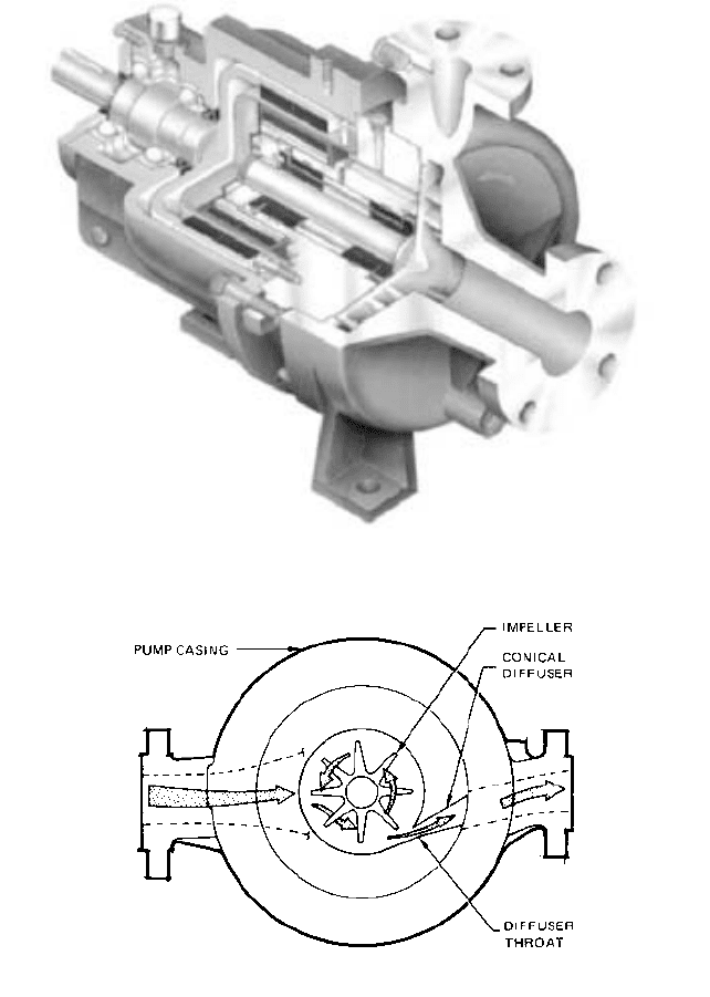
Figure 132 illustrates one manufacturer’s design of a radial-vane high-speed pump.
The impeller rotates in a circular casing that has a single emission point leading to a con-
ical diffusion section. The advantage of this type of casing is that the conversion to pres-
sure occurs outside the circular housing, thus eliminating any recirculation forces that
2.180 CHAPTER TWO
FIGURE 129 A portable submersible pump (Peabody Barnes)
FIGURE 130 Typical canned motor pump (Ref. Subsection 2.2.7) (Crane Chempump)
would require a close clearance between the impeller and casing. For higher flow ranges,
a double emission point design, as shown in Figure 133, is used. This additional emission
acts like a double-volute casing in conventional centrifugal pumps.
2.2.1 CENTRIFUGAL PUMP: MAJOR COMPONENTS 2.181
FIGURE 131 Typical magnetic drive sealless pump (Ref. Subsection 2.2.7) (Flowserve Corporation)
FIGURE 132 A straight-radial-vane impeller in a single emission-point, conical-diffuser circular casing (Sundyne
Corporation)
Figure 134 is a sectional view of this pump with an integral speed increaser. Because
of the high rotative speed, a single-stage pump can achieve the head normally associated
with multistage centrifugal or positive displacement pumps. With this smaller liquid end
and an integral gear box, cost and space savings can be appreciable.