Pump Handbook by Igor J. Karassik, Joseph P. Messina, Paul Cooper, Charles C. Heald - 3rd edition
Подождите немного. Документ загружается.


2.202 CHAPTER TWO
where P
h
p(b—k), lb/in
2
(N/m
2
) and
p pressure differential across seal face, lb/in
2
(N/m
2
)
k pressure gradient factor
b seal balance
The mechanical pressure for a seal design is
where F
sp
seal spring load, lb (N) and
a
o
seal face area, in
2
(m
2
)
Then the actual face pressure can be expressed as
The actual face pressure is used in the estimate of the operating pressure and velocity
for a given seal installation.
Pressure-Velocity As the sealing planes move relative to each other, they are affected
by the actual face pressure and rotational speed. The product of the two, pressure times
velocity, is referred to as PV and is defined as the power N
f
per unit area with a coefficient
of friction of unity:
For seals, the equation for PV can be written as follows:
where V
m
velocity at the mean face diameter dm, ft/min (m/s).
The PV for a given seal installation can be compared with values developed by seal
manufacturers as a measure of adhesive wear.
Power Consumption The PV value also enables the seal user to estimate the power
loss at the seal with the following equation:
where f is the coefficient of friction.
As a rule of thumb, the power to start a seal is generally five times the running value.
The coefficients of friction for various common seal face materials are given in Table 1.
These coefficients were developed with water as a lubricant at an operating PV value of
100,000 lb/in
2
ft/min (35.03 bar m/s). The coefficient of friction is a function of the tribo-
logical properties of the mating pairs of seal face materials and the fluid being sealed. Val-
ues in oil would be slightly higher because of the viscous shear of the fluid film at the seal
faces. For a double or tandem seal, the barrier/buffer oil should have a low viscosity and be
a good lubricant. The values given are suitable for estimating the power loss in a seal.
For example, let’s say we have a pump having a 2-in (50.8-mm) diameter sleeve at the
seal chamber is fitted with a balanced seal of this size and mean diameter. The seal oper-
ates in water at 300 lb/in
2
(20.68 bar), 3,600 rpm, and ambient temperatures. The materi-
als of construction are carbon and tungsten carbide. Determine the PV value and power
loss of the seal, given the following:
N
f
1PV2fa
o
, ft lb>min 1N m>s2
PV P
f
V
m
3¢p1b k2 P
sp
4V
m
PV
N
f
a
o
P
f
¢p1b k2 P
sp
P
sp
F
sp
a
o
, lb>in
2
1N>m
2
2
P
f
P
h
P
sp

2.2.3 CENTRIFUGAL PUMP MECHANICAL SEALS 2.203
TABLE 1 Coefficient of friction for various seal face materials (John Crane Inc.)
Sliding Materials
Rotating Stationary Coefficient of friction
Carbon-graphite Cast iron 0.07
(resin filled) Ceramic 0.07
Tungsten carbide 0.07
Silicon carbide 0.02
Silicon carbide converted carbon 0.015
Silicon carbide Tungsten carbide 0.05
Silicon carbide Silicon carbide converted carbon 0.04
Silicon carbide converted carbon 0.05
Silicon carbide 0.05
Tungsten carbide 0.01
b 0.75
k 0.5
d
m
2 in (50.8 min)
P
sp
25 lb/in
2
(1.72 bar)
V
m
=
a
o
0.4 in
2
(0.000258 m
2
)
f 0.07 (Table 1)
In USCS units:
In SI units:
Temperature Control Controlling the temperature at the seal faces is desirable because
wear is a direct function of temperature. Heat at the seal faces also causes thermal dis-
tortion, which will contribute to increased seal leakage. Many applications require some
type of cooling.
The temperature of the sealing surfaces is a function of the heat generated by the seal,
plus the heat gained or lost to the pumpage.The heat generated at the faces from sliding con-
tact is the mechanical power consumption of the seal being transferred into heat. Therefore,
where Q
s
heat input from the seal, Btu/h(W) and
C
1
0.077 for USCS units and 1 for SI units
If the heat is removed at the same rate it is produced, the temperature will not increase.
If the amount of heat removed is less than that generated, the seal face temperature will
Q
s
C
a
N
f
C
1
1PVfa
o
2
N
f
166 10
5
210.07212.58 10
4
2 119 N
#
m>s 119 W
PV 320,6810.75 0.52 1.72419.572 66 bar
#
m>s 66 10
5
N>m
2
#
m>s
N
f
1188,400210.07210.42 5275 ft
#
lb>min 0.16 hp
PV 330010.75 0.52 254118852 188,400 lb>in
2
#
ft>min
p
12
2 3600 1885 ft>min a
p 50.8 3600
1000 60
9.57 m>s
b
¢p 300 lb>in
2
120.68 bar2
2.204 CHAPTER TWO
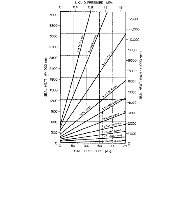
FIGURE 7 Unbalanced seal heat generation (John Crane Inc.)
increase to a point where seal face damage will occur. The estimated values for heat input
are given in Figures 7 and 8.
Heat removal from a single seal is accomplished by a seal flush. The seal flush is usu-
ally a bypass from the discharge line on the pump or an injection from an external source.
The flow rate for cooling can be found by calculating the following:
where Q
s
seal heat, Btu/h(W)
C
2
500 in USCS units and 1,000 in SI units
sp. ht. specific heat of coolant,
sp. gr. specific gravity of coolant
T temperature rise, °F (K)
When handling liquids at elevated temperatures, the heat input from the process must
be considered in the calculation of coolant flow. Thus,
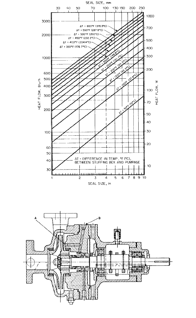
The heat load Q
p
from the process can be determined from Figure 9.
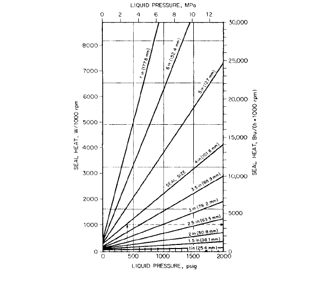
As an example, let’s determine the net heat input for a 4-in (102-mm) diameter bal-
anced seal in water at 1,800 rpm. The pressure and temperature are 400 lb/in
2
(27.6 bar)
and 170°F (76.7°C). From Figure 8, we have the following:
In USCS units:
Q
s
13500 Btu>h>1000 rpm2 118002 6300 Btu>h
Q
net
Q
p
Q
s
1J>kg
#
K2Btu>lb.
#
°F
gpm 1m
3
>h2
Q
s
C
2
1sp. ht.21sp. gr.2¢T
2.2.3 CENTRIFUGAL PUMP MECHANICAL SEALS 2.205
FIGURE 8 Balanced seal heat generation (John Crane Inc.)
In SI units:
From Figure 9, assuming that the seal chamber will be cooled to 70°F (21°C) and that
the temperature difference between the seal chamber and pumpage is 100°F (37.8°C), we
have the following:
In USCS units:
In USCS units:
The total heat input can be used to estimate the required flow to the seal. When mul-
tiple seals are used in a pump seal chamber, the heat load from each seal must be consid-
ered as well as any heat soak from the process.
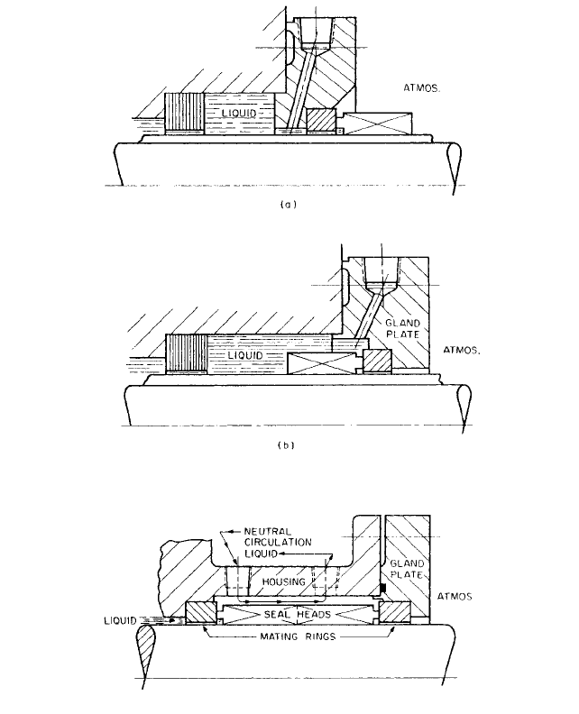
Different methods are used to supply cool liquid to the seal chamber (see Figure 10).
When the liquid is clean, an internal flush connection at (A) can be used to cool the seal.
When the liquid is dirty, an external flush at (B) can be used. This will allow the flush, a
bypass from the discharge line, to pass through a filter or centrifugal separator. The seal
faces will be flushed with clean, cool liquid. Increased pressure from the flush provides
positive circulation and prevents flashing at the seal faces caused by the heat generation.
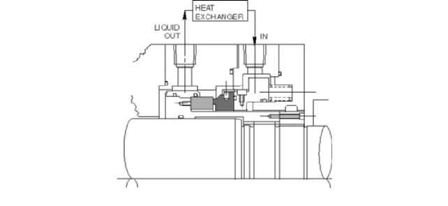
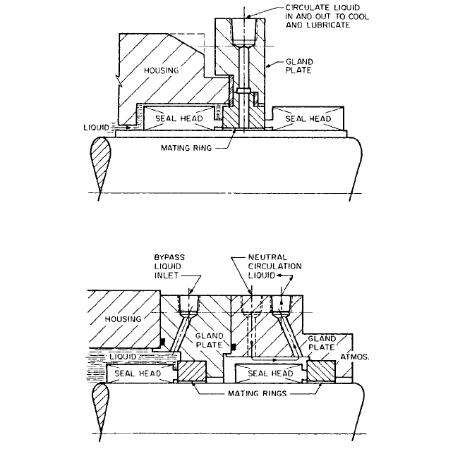
When a pump handles liquids near their boiling point, additional cooling of the seal
chamber is required.A typical arrangement to accomplish this is shown in Figure 11. This
seal is equipped with a pumping ring and a heat exchanger. The pumping ring acts as a
miniature pump, causing the liquid to flow through the outlet piping at the top of the seal
Q
net
6555 Btu>h 11920 W2
Q
p
75 W
Q
p
255 Btu>h
Q
s
11025 W>1000 rpm2 118002 1845 W
2.206 CHAPTER TWO
FIGURE 10 Cooling circulation to mechanical seal: (A) internal circulation plug port, (B) external circulation
plug port
FIGURE 9 Heat soak from process when water is used for lubrication (John Crane Inc.)
2.2.3 CENTRIFUGAL PUMP MECHANICAL SEALS 2.207
FIGURE 11 High performance boiler feed pump seal with external cooling
chamber. The liquid passes through the heat exchanger and returns directly to the faces
at the bottom inlet in the end plate. As the liquid is circulated, heat is removed from the
seal and seal chamber. A closed loop system is commonly used on hot water pumps. This
method is extremely efficient since the coolant is circulated only in the seal chamber and
does not reduce the temperature of the liquid in the pump.
It should be noted that during periods of shutdown different wear problems might exist
because the seal faces may be too cold. The product being pumped may be a solution that
can crystallize or solidify at ambient temperatures. For these applications, the seal faces
may have to be preheated before starting to avoid damage to the seal.
Leakage Leakage is affected by the parallelism of the sealing planes, angular mis-
alignment, coning (negative face rotation), thermal distortion (positive face rotation), shaft
runout, axial vibration, and fluctuating pressure. For parallel faces only, which take into
account seal geometry only, the theoretical leakage in cubic centimeters per hour can be
estimated from the following:
where C
3
2.13 10
10
in USCS units and 1.88 10
9
in SI units
h face gap, in (m)
P
2
pressure at face ID, lb/in
2
(N/m
2
)
P
1
pressure at face OD, lb/in
2
(N/m
2
)
u dynamic viscosity, C
p
(N s/m
2
)
R
2
outer face radius, in (m)
R
1
inner face radius, in (m)
Negative leakage indicates flow from the face’s outer diameter to the inner diameter.
The effect of centrifugal force from one of the rotating sealing planes is very small and can
be neglected in normal pump applications. The gap between the seal face is a function of
the materials of construction, flatness, and the liquid being sealed. The face gap can range
from 20 10
6
to 50 10
6
in (0.508 10
6
to 1.27 10
6
m).
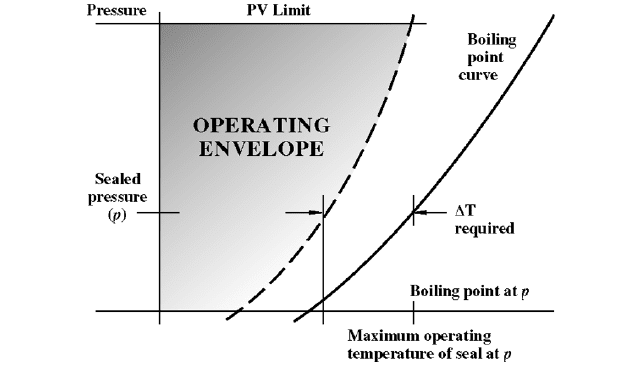
Contacting Seal Operating Envelope Every seal has an operating envelope.The basic
envelope for a contacting seal is shown in Figure 12. The upper limits are defined by wear
of the seal faces, usually defined by a pressure-velocity limit.The fluid being sealed should
be cooled so the liquid at the seal faces does not flash. Operating within the envelope will
result in excellent seal performance.
Q
3
C
3
h
3
1P
2
P
1
2>u ln 1R
2
>R
1
2
2.208 CHAPTER TWO
FIGURE 12 Operating envelope for a contacting seal
CLASSIFICATION OF SEALS BY ARRANGEMENT _________________________
Sealing arrangements can be classified into two groups:
1. Single seal installations
a. Internally mounted
b. Externally mounted
2. Multiple seal installations
a. Double seals
b. Tandem seals
Single seals are used in most applications. This is the simplest seal arrangement with
the least number of parts.An installation can be referred to as inside-mounted or outside-
mounted, depending on whether the seal is mounted inside or outside the seal chamber
(see Figure 13). The most common installation is an inside-mounted seal. Here the liquid
under pressure acts with the spring load to keep the seal faces in contact.
Outside-mounted seals are considered to be used for low-pressure applications since
both seal faces, the primary ring and mating ring, are put in tension. This limits the pres-
sure capability of the seal. An external seal installation is used to minimize corrosion that
might occur if the metal parts of the seal were directly exposed to the liquid being sealed.
Multiple seals are used in applications requiring
• A neutral liquid for lubrication
• Improved corrosion resistance
• A buffered area for plant safety
Double seals consist of two single seals back to back, with the primary rings facing in
opposite directions in the seal chamber. The neutral liquid, at a pressure higher than that
of the liquid being pumped, lubricates the seal faces (see Figure 14). The inboard seal
keeps the liquid being pumped from entering the seal chamber. Both inboard and outboard
seals prevent the loss of neutral lubricating liquid.
2.2.3 CENTRIFUGAL PUMP MECHANICAL SEALS 2.209
FIGURE 13 Single seal installations: a) outside mounted, b) inside mounted
FIGURE 14 Double Seals
Double seals can be used in an opposed arrangement. Two seals are mounted face to
face, with the primary sealing rings rotating on a common mating ring (see Figure 15). In
this case, the neutral liquid is circulated between the seals at a pressure lower than that
of the process fluid. This pressure is limited since the outboard seal faces are in tension.
The inboard seal is similar to a single inside-mounted seal and carries the full differential
pressure of the seal chamber to the neutral liquid.The outboard seal carries only the pres-
sure of the neutral liquid to the atmosphere. The purpose of this arrangement is to fit a
seal installation having a shorter axial length than is possible with back-to-back double
seals and still form a buffered area for plant safety.
Tandem seals are arranged with two single seals mounted in the same direction (see
Figure 16). The outboard seal and neutral liquid create a buffer zone between the liquid
being pumped and the atmosphere. Normally, the pressure differential from the liquid
2.210 CHAPTER TWO
FIGURE 16 Tandem seals
FIGURE 15 Opposed double seals
being sealed and atmosphere is taken across the inboard seal, while the neutral lubricat-
ing liquid is at atmosphere pressure. This arrangement can also be used as a method to
break down the pressure on high-pressure applications. For example, the pressure differ-
ence across each seal can be half the fluid pressure being sealed.The liquid in the outboard
seal chamber may be circulated to remove seal heat. Tandem seals are used on toxic or
flammable liquids, which require a buffered or safety zone.
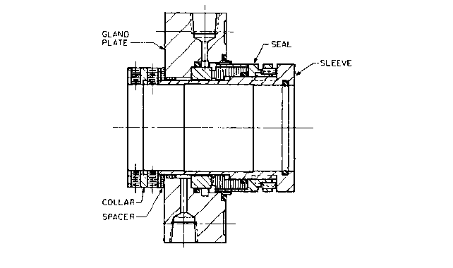
Package or cartridge seals are an extension of other seal arrangements.A package seal
requires no special measurements prior to seal installation. For a single seal, the seal
package consists of the gland plate, sleeve, and drive collar (see Figure 17).A spacer is pro-
vided on most package seals to properly set the seal faces. The spacer is removed after the
drive collar has been locked to the shaft and the gland plate bolted to the pump.
CLASSIFICATION OF SEALS BY DESIGN ________________________________
There are four seal classification groups:
• Unbalanced or balanced
• Rotating or stationary seal head
2.2.3 CENTRIFUGAL PUMP MECHANICAL SEALS 2.211
FIGURE 17 A single package (cartridge) seal assembly (John Crane Inc.)
• Single-spring or multiple-spring construction
• Pusher or nonpusher secondary seal design
The selection of an unbalanced or balanced seal is determined by the pressure in the
seal chamber. Balance is a way of controlling the contact pressure between the seal faces
and power generated by the seal. When the percentage of balance b (the ratio of hydraulic
closing area to seal face area) is 100 percent or greater, the seal is referred to as unbal-
anced. When the percentage of balance for a seal is less than 100 (1.0), the seal is balanced.
Figure 18 illustrates common unbalanced and balanced seals.
The selection of a rotating or stationary seal is determined by the speed of the pump shaft.
A seal that rotates with the shaft is a rotating seal assembly. Typical rotating seals are shown
in Figures 17, 21 and 22. When the mating ring rotates with the shaft, the seal is stationary
(see Figure 19). Rotating seal heads are common in the industry for normal pump shaft
speeds. As a rule of thumb, when the shaft speed exceeds 5,000 ft/min (25.4 m/s), stationary
seals are required. Higher speed applications require a rotating mating ring to keep unbal-
anced forces, which may result in seal vibration, to a minimum. A stationary seal should be
considered for all split case pumps.This will eliminate seal problems that occur when the top
and bottom halves of the pump casing do not line up. The pressure in the pump can cause a
misalignment of these parts that creates an out-of-square condition at the seal faces.
The selection of a single-spring or multiple-spring seal head construction is determined
by the space limits and the liquid sealed. Single-spring seals are most often used with bel-
lows seals to load the seal faces (see Figure 20a). The advantage of this type of construc-
tion is that the openness of design makes the spring a nonclogging component of the seal
assembly. The coils are made of a large diameter spring wire and therefore can withstand
a great deal of corrosion.
Multiple-spring seals require a shorter axial space. Face loading is accomplished by a
combination of springs placed about the circumference of the shaft (refer to Figure 1 and
see Figure 20b). Most multiple-spring designs are used with assemblies having O-rings or
wedges as secondary seals.
Pusher-type seals are defined as seal assemblies in which the secondary seal is moved
along the shaft by the mechanical load of the seal and the hydraulic pressure in the seal
chamber. The designation applies to seals that use an O-ring, wedge, or V-ring. A typical
construction is illustrated in Figure 21.
The primary ring, with a hardened metal surface, rotates with the shaft and is held
against the stationary ring by the compression ring through loading of the O-ring. The