Pump Handbook by Igor J. Karassik, Joseph P. Messina, Paul Cooper, Charles C. Heald - 3rd edition
Подождите немного. Документ загружается.

2.222 CHAPTER TWO
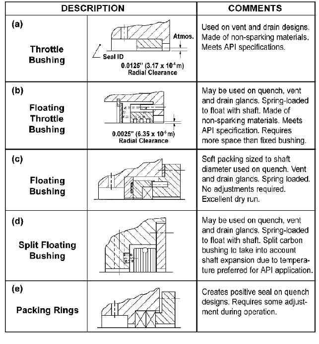
FIGURE 35 Common restrictive devices used with quench, or vent and drain gland plates.
pumps was accelerated in the early 1990s as a way to control emissions. Eliminating the
contact between the seal faces while the pump shaft is turning also eliminates the tribo-
logical problems of frictional heat and wear. This is no easy task with a liquid present in
the pump. Deflections of the seal faces from temperature and pressure must be controlled
to very precise levels. Gas, rather than a liquid, must be used as a barrier fluid and one of
the seal faces must be designed with a lift mechanism.
A lift mechanism can take the shape of a spiral groove, an L-shaped slot, or a controlled
wavy surface. When the shaft turns, pressure builds up in the seal faces, which causes the
face separation. The basic construction of a spiral groove face and the pressure buildup is
shown in Figure 37. The separation of the face is very small and could be measured in
nanometers, which enables a small amount of gas to flow across the seal face. Since this
type of seal is non-contacting, the only heat that is developed is from the shearing of gas
at the seal faces. The small amount of gas flow helps cool the seal faces. The temperature
rise at the seal faces is just a few degrees, making this a preferred seal for heat-sensitive
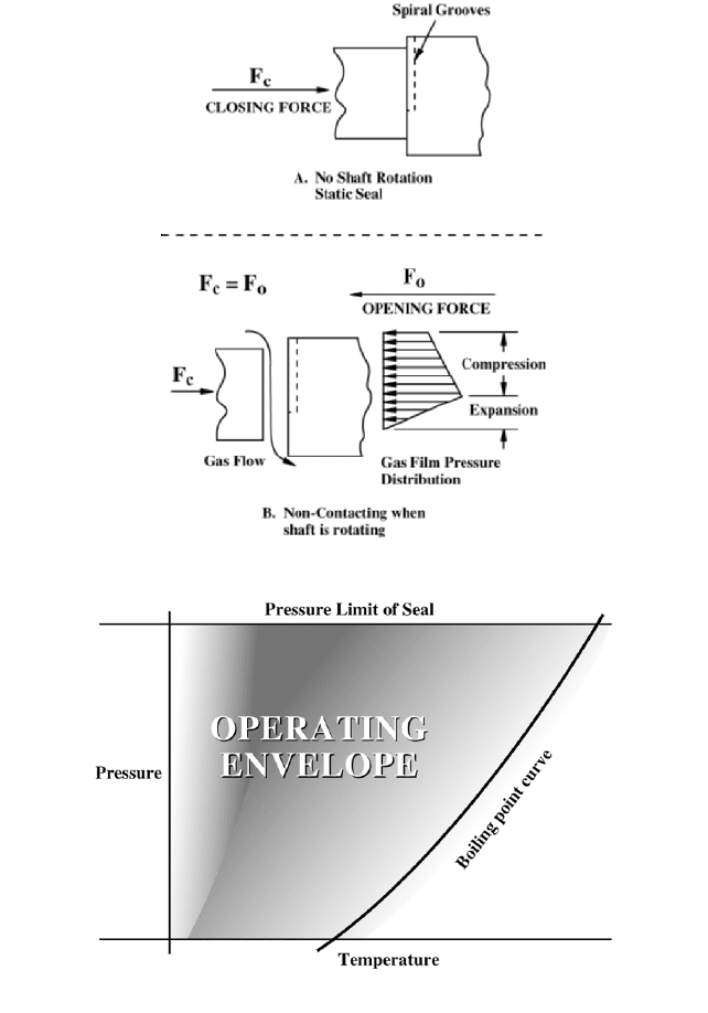
liquids. The processes occurring at the seal faces are shown in Figure 38.
The operating envelope for a non-contacting, gas-lubricated seal for liquid pumping
services is shown in Figure 39. Since the rubbing contact at the seal faces has been elim-
2.2.3 CENTRIFUGAL PUMP MECHANICAL SEALS 2.223
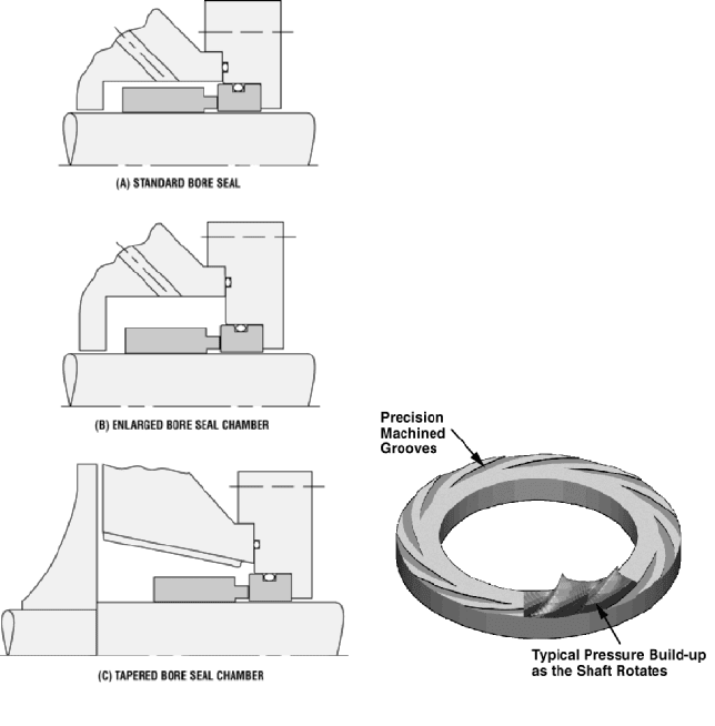
FIGURE 36 Standard bore, enlarged bore, and
tapered bore seal chamber arrangements.
FIGURE 37 Spiral groove seal face and pressure
build up in the grooves (John Crane Inc.)
inated, the seal can be operated at the vapor pressure of the liquid being sealed. In addi-
tion, no limiting factor exists due to the pressure-velocity relationship and wear at the seal
faces.The limiting factor in the application of the seal is the pressure that has an effect on
seal face deflection.
Dual pressurized, gas-lubricated seals have been designed to fit oversized and small
bore seal chambers. An oversized seal chamber that enables a larger cross-section seal and
that can handle pressures up to 600 psig (40 bar) is illustrated in Figure 40.Many exist-
ing pumps in the field have small bore seal chambers and do not require the same pres-
sure capability as a larger cross-section seal. The seal to fit these units is illustrated in
Figure 41. This type of seal is being used to pressures of 230 psig (16 bar).
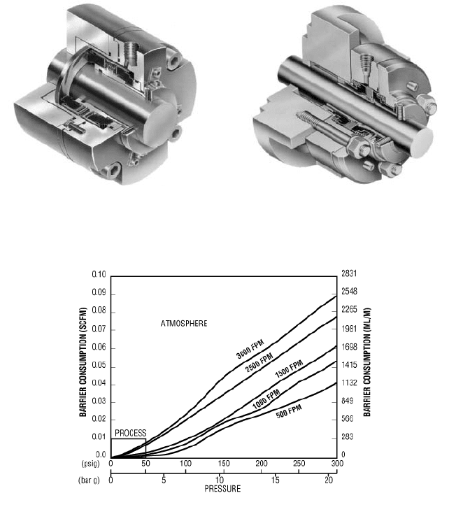
Dual seals are pressurized with an inert gas. Gas pressure is normally 20 to 30 psig
(1.4 to 2 bar) above the process liquid being sealed. The amount of gas consumed through
a dual seal can be estimated from Figure 42. The gas consumption is the sum of the flow
across the inboard and outboard seals.The amount of gas consumed on an annual basis is
very small. This makes this type of installation very economical when compared to a fully
pressurized liquid barrier/buffer system. Gas pressure and flow are monitored by a safety
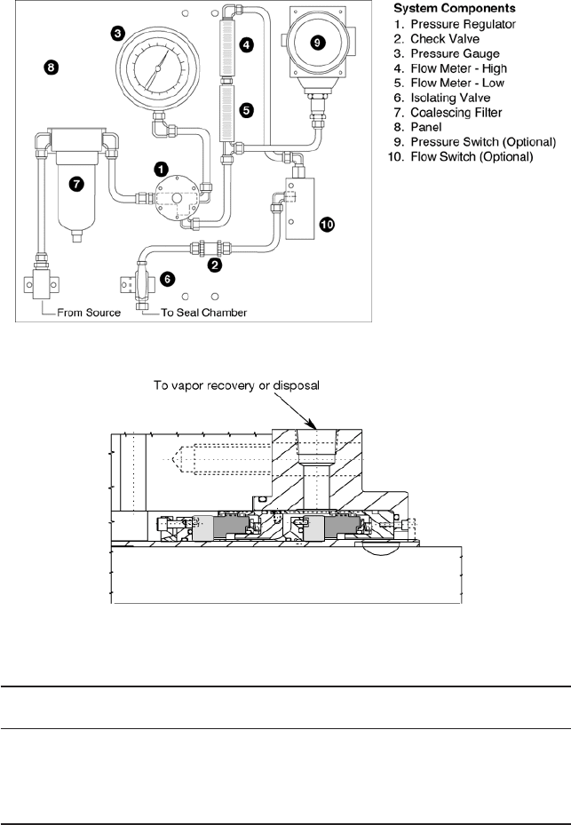
gas panel like that shown in Figure 43.
This technology represents a solution for those sealing problems that affect the cooling
and lubrication of a contacting seal by the liquid being sealed. These problems, identified
2.224 CHAPTER TWO
FIGURE 38 The processes occurring at the seal faces
by users as reasons for a short seal life, include a loss of seal flush, dry running, startup
without venting, low net positive suction head (NPSH), and cavitation. Cavitation may
also result in vibration of the equipment. The vibration limit for a non-contacting gas
lubricated seal is 0.4 in/s (10 mm/s). The benefits of this technology are increased perfor-
mance, emissions control, safety, reliability, and efficiency for a conventional pump fitted
FIGURE 39 The operating envelope for a non-contacting, gas-lubricated seal for liquid pumping services. (John
Crane Inc.)
2.2.3 CENTRIFUGAL PUMP MECHANICAL SEALS 2.225
FIGURE 40 Non-contacting gas-lubricated seal for
pumps with a large bore seal chamber (John Crane
Inc.)
FIGURE 41 Non-contacting gas-lubricated seal for
pumps with a small cross-section seal chamber (John
Crane Inc.)
FIGURE 42 Gas consumption through a seal face. (John Crane Inc.)
with non-contacting gas lubricated seals. This translates into increased mean time
between maintenance (MTBM) and reduced costs of ownership of the equipment. An inert
gas, such as nitrogen, is a preferred barrier fluid in refinery and petrochemical industries,
while purified air is used in the pharmaceutical and biotech industries. Protecting the
environment is the main reason for the development of this technology, but, it is also a pri-
mary sealing system used to maintain product purity in the pharmaceutical and biotech
industries.
Pumping liquid near its vapor pressure represents a challenge to equipment manu-
facturers and plant operators.Trying to seal this type of application with a contacting seal
will result in an inefficient installation. The amount of heat generated would require too
much cooling to prevent the liquid from flashing. The only solution is to eliminate the heat
generated at the seal faces, allowing the liquid being sealed to flash to a gas and use a non-
contacting gas lubricated seal.
For those liquids that are dangerous to the environment, a tandem seal arrangement
would be used. The space between the seals would be vented to a flair or vapor disposal
2.226 CHAPTER TWO
FIGURE 43 A safety gas panel for monitoring gas pressure and flow (John Crane Inc.)
FIGURE 44 Early non-contacting gas-lubricated seal design for vaporizing hydrocarbon service (John Crane Inc.)
TABLE 2 Typical vaporizing hydrocarbon services (John Crane Inc.)
Operating Condition/ Pressure Temperature Speed
Seal Size (in) Liquid (lb/in
2
) (Degree F) Min/Max (rpm)
1.250 Ethane 554 45 / 125 3,560
1.875 LNG 327 37 / 125 3,560
2.875 LNG 400 30 / 125 3,560
3.375 Ethane 392 49 / 125 1,750
5.250 LNG 850 30 / 125 3,560
area. Figure 44 represents an early tandem seal arrangement for this type of service.
Applying this technology to pumps has resulted in a significant increase in equipment reli-
ability. A list of typical applications for non-contacting gas seals to be applied to vaporiz-
ing hydrocarbon liquid services is shown in Table 2.
2.2.3 CENTRIFUGAL PUMP MECHANICAL SEALS 2.227
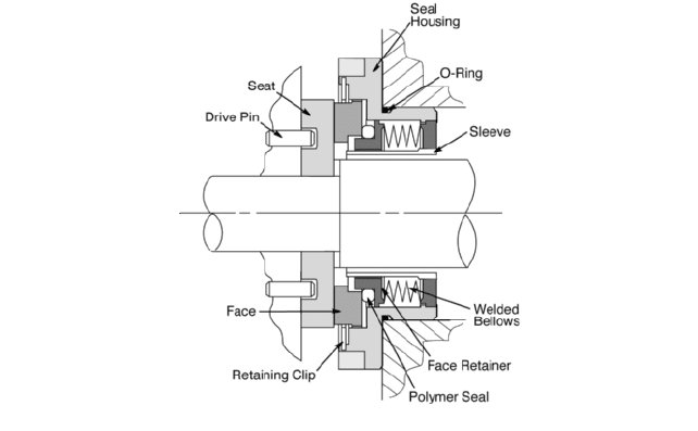
FIGURE 45 A non-contacting gas-lubricated seal for cryogenic service (John Crane Inc.)
Cryogenic liquids represent a similar design challenge in sealing technology. Tradi-
tionally, pumps that are used to pump these liquids relied on contacting seal designs.
Although these fluids were at cryogenic temperatures, the seals were operating near the
boiling point of the liquid. Frictional heat was enough to vaporize or flash the liquid to a
gas. This resulted in short seal life. By allowing the liquid to flash to a gas and by using
non-contacting gas lubricated seals, seal life has been extended from weeks to years. A
non-contacting gas lubricated cryogenic seal is illustrated in Figure 45. Due to the low
temperatures involved, a metal bellows is required in the seal design.
MATERIALS OF CONSTRUCTION _______________________________________
All component parts of a seal are selected based on their corrosion resistance to the liquid
being sealed. The National Association of Corrosion Engineers (NACE) Corrosion Hand-
book provides corrosion rates for many materials of construction for mechanical seals used
with a variety of liquids and gases.When the corrosion rate is greater than two mils (0.05
mm) per year, double seals that keep the hardware items of the seal in a neutral liquid
should be selected to reduce corrosion. In this design, only the inside diameter of the mat-
ing ring, the primary ring, and the secondary seal are exposed to the corrosive liquid and
should be constructed of corrosion-resistant materials, such as ceramic, carbon, and Teflon.
Common materials of construction are given in Table 3. Table 4 lists the properties of com-
mon seal face materials.
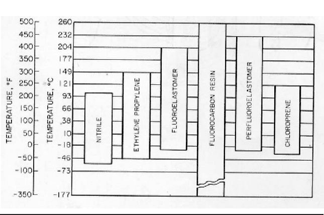
The operating temperature is a primary consideration in the design of the secondary
and static seals in the assembly. These parts must retain their flexibility throughout the
life of the seal, as flexibility is necessary to retain the liquid at the secondary seal as well
as to enable a degree of freedom for the primary ring to follow the mating ring.The usable
temperature limits for common secondary and static seal materials are given in Table 5.
An additional consideration in the selection of the primary and mating ring materials
in sliding contact is their PV limitation. This value is an indication of how well the mate-
rial combination will resist adhesive wear, which is the dominant wear in mechanical
seals. Limiting PV values for various face combinations are given in Table 6. Each limit-
ing value has been developed for a wear rate that provides an equivalent seal life of two
years. A PV value for an individual application can be compared with the limiting PV

2.228 CHAPTER TWO
TABLE 3 Common materials of construction for mechanical seals
Components Materials of Construction
Secondary Seals:
O-rings Nitrile, Ethylene Propylene, Chloroprene, Fluoroelastomer,
Perfluoroelastomer
Bellows Nitrile, Ethylene Propylene, Chloroprene, Fluoroelastomer
Wedge or U Cups Fluorocarbon
Metal Bellows Stainless steel, Nickel-base Alloy
Primary Ring Carbon, Metal-filled Carbon, Tungsten Carbide,
Silicon Carbide, Siliconized Carbon, Bronze
Hardware (retainer, Stainless Steel, Nickel-base Alloy
disc, snap rings, set
screws, springs)
Mating Ring Ceramic, Cast Iron, Tungsten Carbide, Silicon Carbide
value for the materials used to determine satisfactory service.These values apply to aque-
ous solutions at 120°F (49°C). For lubricating liquids such as oil, values of 60 percent or
higher can be used. Higher or lower values of PV may apply, depending on the seal face
design.
INSTALLING THE SEAL AND IDENTIFYING CAUSES OF SEAL LEAKAGE _____
A successful seal installation requires operation of the pump within the manufacturer’s
specification. Relative movement between the seal parts or shaft sleeve usually indicates
that mechanical motion has been transmitted to the seal parts from misalignment (angu-
lar or parallel), endplay, or radial runout of the pump (see Figure 46).
Angular misalignment results when the mating ring is not square with the shaft and
will cause excessive movement of internal seal parts as the primary ring follows the out-
of-square mating ring. This movement will fret the sleeve or seal hardware on pusher
type seal designs. Angular misalignment may also occur from a seal chamber that has
been distorted by piping strain developed at operating temperatures. Damage in the
wearing rings can also be found here if the pump seal chamber has been distorted.
Parallel misalignment results when the seal chamber is not properly aligned with the
rest of the pump. No seal problems will occur unless the shaft strikes the inside diameter
of the mating ring. If damage has occurred, there will also be damage to the bushing at the
bottom of the seal chamber at the same location as the mating ring.
Excessive axial endplay can damage the seal surfaces and cause fretting. If the seal is
continually being loaded and unloaded, abrasives can penetrate the seal faces and cause
premature wear of the primary and mating rings. Thermal damage in the form of heat
checking in the seal faces because of excessive endplay can occur if the seal is operated
below working height.
Radial runout in excess of limits established by the pump manufacturer could cause
excessive vibration at the seal. This vibration, coupled with small amounts of the other
types of motion that have been defined, will shorten seal life.
Instructions and seal drawings should be reviewed to determine the installation
dimension or spacing required to ensure that the seal is at its proper working height (see
Figure 47). The installation reference can be determined by locating the face of the seal
chamber on the surface of the sleeve and then measuring along the sleeve after it has been

2.229
TABLE 4 Typical properties of common seal face material
CERAMIC CARBIDES CARBON
85% 99% Tungsten Silicon
Property Cast Iron Ni-resist (AL
2
O
3
) (AL
2
O
3
) (6% Co) (SiC) Resin Antimony Bronze SiC Conv.
Modulus of Elasticity 13–15.95 10.5–16.9 32 50 90 48–57 2.5–4.0 3.8–4.8 2.9–4.4 2-2.
10
6
lb/in
2
(90–110) 72–117) (221) (245) (621) (331–393) (17.2–27.6) (26.2–33.1) (20–30) (13.8–15.9)
( 10
3
Mpa)
Tensile Strength 65–120 20–45 20 39 123.25 20.65 4.5–97.5–9.0 7.5–92
10
3
lb/in
2
(Mpa) (448–827) (138–310) (138) (269) (8;50) (142) (31–62) (52–62) (52–62) (14)
Coefficient of Thermal 6.6 6.5–6.8 3.9 4.3 2.53 1.88 2.3.–3.4 2.3.–4.7 2.4–3.1 2.4–3.2
Expansion 10
6
(11.88) (11.7–12.24) (7.02) (7.74) (4.55) (4.55) (4.14–6.12) (4.14–8.46) (4.32–5.58) (4.32–5.76)
in/in F (cm/cm K)
Thermal Conductivity 23–29 25–28 8.5 14.5 41–48 41–60 3.8–12 5.8–9.0 8–8.5 30
Btu ft/h ft
2
ºF (39.79–50.17) (43.25–48.44) (14.70) (25.08) (70.93–83.04) (70.93–103.8) (6.57–20.76) (10.0–15.6) (13.84–14.70) (51.9)
(w/m k)
Density: 0.259–0.268 0.264–0.268 0.123 0.137 0.50 0.104 0.064–0.069 0.083–0.112 0.083–0.097 0.067–0.070
lb/in
3
(kg/m
3
) (7169–7418) (7307–7418) (3405) (3792) (16.331) (2879) (1771–1910) (2297–3100) (2297–2685) (1854–1938)
Brinell Rockwell A Rockwell 45N Shore Rockwell 15T
Hardness 217–269 131–183 87 87 92 86–88 80–105 75–100 70–92 90
2.230 CHAPTER TWO
TABLE 5 Temperature limits of secondary seal materials
removed from the unit. It is not necessary to use this procedure if a step in the sleeve or
collar has been designed into the assembly to provide for proper seal setting. Assembling
other parts of the seal will bring the unit to its correct working height.
All package or cartridge shaft seals can be assembled with relative ease because just
the bolts at the gland plate and set screws on the drive collar need to be fastened to the
seal chamber and shaft. After the seal spacer is removed, the unit is ready to operate.
To assemble a mechanical seal to a pump, a spacer coupling is required. If the pump is
packed but may later be converted to mechanical seals, a spacer coupling should be
included in the pump design.
Since a seal has precision-lapped faces and because secondary seal surfaces are criti-
cal in the assembly, installations to the equipment should be kept as clean as possible. All
lead edges on sleeves and glands should have sufficient chamfers to facilitate installation.
When mechanical seals are properly applied, there should be no static leakage and,
under normal conditions, the amount of dynamic leakage should range from none to just
a few drops per minute. Under a full vacuum, a mechanical seal is used to prevent air from
leaking into the pump. If excessive leakage occurs, the cause must be identified and cor-
rected. Causes for seal leakage with possible corrections are listed in Table 7. In addition,
Figure 48 illustrates the most common causes for mechanical seal leakage. Further infor-
mation on seal leakage and the related condition of seal parts can be found in the works
listed in the “Further Reading” section.

2.2.3 CENTRIFUGAL PUMP MECHANICAL SEALS 2.231
TABLE 6 Frequently used seal face materials and their PV limitations
PV limit,
Sliding Materials
lb/in
2
ft/min
Rotating Stationary (bar m/s) Comments
Carbon-graphite Ni-resist 100,000 Better thermal shock resistance
(35.03) than ceramic
Ceramic 100,000 Poor thermal shock resistance and
(85% Al
2
O
3
) (35.03) much better corrosion resis-
tance than Ni-resist
Ceramic 100,000 Better corrosion resistance than
(99% Al
2
O
3
) (35.03) 85% Al
2
O
3
Ceramic
Tungsten 500,000 With bronze-filled carbon
Carbide (175.15) graphite, PV is up to 100,000
(6% Co) lb/in
2
ft/min (35.02 bar m/s)
Tungsten 500,000 Ni binder for better corrosion
Carbide (175.15) resistance
(6% Ni)
Silicon Carbide 500,000 Good wear resistance; thin layer
(converted (175.15) of SiC makes relapping
Carbon) questionable
Silicon Carbide 500,000 Better corrosion resistance than
(solid) (175.15) Tungsten Carbide but poorer
thermal shock resistance
Carbon-graphite 500,000 Low PV, but very good against
(17.51) face blistering
Ceramic 10,000 Good service on sealing paint
(3.50) pigments
Tungsten Carbide 120,000 PV is up to 185,000 lb/in
2
ft/min
(42.04) (64.8 bar m/s) with two grades
that have different % of binder
Tungsten Carbide/ 300,000 Excellent abrasion resistance.
Silicon Carbide (105.1) Commonly used on high
(solid) temperature applications
Silicon Carbide 500,000 Excellent abrasion resistance,
(converted (175.15) more economical than solid
carbon) Silicon Carbide
Silicon Carbide 350,000 Excellent abrasion resistance,
(solid) (122.6) good corrosion resistance and
moderate thermal shock
resistance