Pump Handbook by Igor J. Karassik, Joseph P. Messina, Paul Cooper, Charles C. Heald - 3rd edition
Подождите немного. Документ загружается.

2.2.5 CENTRIFUGAL PUMP OIL FILM JOURNAL BEARINGS 2.253
(19)
where Re Reynolds number
r fluid density, lb s
2
/in
4
(kg/m
3
)
u surface velocity, in/s (m/s)
h local film thickness, in (m)
m viscosity, lb s/in
2
(Pa s)
A reasonable approximation is to use the concentric clearance c for h. In terms of N
rpm and journal diameter D, the Reynolds number is
(20)
The criterion for turbulence in journal bearings is that Re 1000.
EXAMPLE As an example, consider the following:
Journal diameter D 5 in (127 mm)
Bearing length L 5 in (127 mm)
Radial clearance c 0.0025 in (0.064 mm)
Operating speed N 5000 rpm
Lubricant viscosity
Lubricant density
Thus, the bearing is operating in the laminar regime. To become turbulent (assum-
ing constant viscosity), the operating speed would have to increase to approximately
38,500 rpm.
The example cited is for a relatively high-speed, oil-lubricated bearing for pump appli-
cations. In general, most pump bearings operate in the laminar regime. Exceptions might
occur when water is used as tbe lubricant because it its much less viscous than oil.
Evaluation of Frictional Losses It is often desirable to obtain a quick estimate of vis-
cous drag losses that the journal bearings produce. If we consider shear forces again, we
return to the laminar flow equation:
(21)
where F viscous shear force, lb (N)
m viscosity, lb s/in
2
(Pa s)
A surface area, in
2
(m
2
)
u journal velocity, in/s (m/s)
h film thickness, in (m)
To obtain friction, we multiply both sides of Equation 21 by the journal radius R. Then
the viscous frictional moment is
M mAR
u
h
F mA
m
h
7.95 10
5
p 5 5000
60
0.0025
2 10
6
130
Re r
pDN
60
c
m
r 7.95 10
5
lb s
2
>in
4
18.66 10
11
kg s
2
>mm
4
2
m 2 10
6
lb s>in
2
114 10
3
Pa s2
Re r
pDN
60
c
m
Re
ruh
m

2.254 CHAPTER 2
The frictional horsepower loss is
where N rotating speed, rpm
M moment, lb in (N m)
Also
A surface area of bearing pDL, in
2
(m
2
)
Substituting, we obtain
(22)
In obtaining approximate losses for estimation purposes, the concentric clearance c is
substituted for the local film thickness h.
If we consider the previous example where D 5 in (127 mm), L 5 in (127 mm), c
0.0025 in (0.064 mm), N 5000 rpm, and m 2 10
6
lb s/in
2
(14 10
3
Pa s), the
horsepower loss is
Note that for thrust bearings, the frictional horsepower loss is
(23)
where OD outside diameter
ID inside diameter
A general rule of thumb is that the frictional horsepower in a thrust bearing is approx-
imately twice that in a journal bearing.
BEARING TYPES _____________________________________________________
Cylindrical Bearing
The most common type of journal bearing is the plain cylindrical
bushing shown schematically in Figure 1. It can be split and have lubricating feed grooves
at the parting line. A ramification is to incorporate axial grooves to enable better cooling
and to improve whirl stability (described in more detail below in the discussion of cylin-
drical bearings with axial grooves). The principle advantages of cylindrical bearings are (1)
simple construction and (2) a high-load capacity relative to other bearing configurations.
This type of bearing also has several disadvantages:
• Whirl Instability: This is prone to subsynchronous whirling at high speeds and also at
low loads. Whirling is an orbiting of the journal (shaft) center in the bearing, a motion
that is superimposed upon the normal journal rotation. The orbital frequency is
approximately half the rotating speed of the shaft. The expression half-frequency whirl
is commonly used. The reason for the occurrence of this whirl and more details
concerning bearing dynamics are presented in the section on bearing dynamics.
• Viscous Heat Generation: Because of the generally large and uninterrupted surface area
of this bearing, it generates more viscous power loss than some other types.
FHP
mN
2
h
OD
4
ID
4
6.127 10
6
FHP
12 10
6
2152152
3
150002
2
1766,000210.00252
16.32 hp
FHP
m L D
3
N
2
766,000h
u surface speed
pDN
60
in>s 1m>s2
FHP
NM
63,000
2.2.5 CENTRIFUGAL PUMP OIL FILM JOURNAL BEARINGS 2.255
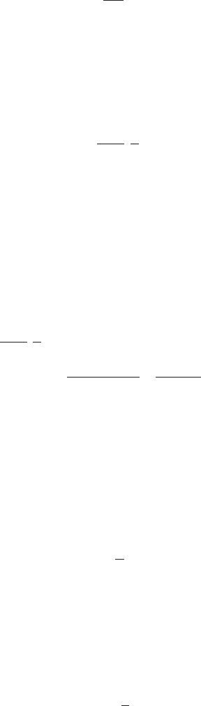
FIGURE 7 Cylindrical bearing with axial grooving.
• Contamination: The cylindrical bearing is more susceptible to contamination problems
than other types because contaminants that are dragged in at the leading edge of the
bearing cannot easily dislodge because of the absence of grooves or other escape paths.
The advantages of simplicity and load capacity make the plain journal a leading can-
didate for most applications, but performance should be carefully investigated for whirl
instability and potential thermal problems. Cylindrical bearings are generally used for
medium-speed (500 in/s [200 mm/sec] surface speed) and medium- to heavy-load applica-
tions (250 to 400 lb/in
2
[17 to 28 bar] on a projected area).
Cylindrical Bearing with Axial Grooves A typical configuration of this type of bear-
ing is a plain cylindrical bearing with four equally spaced longitudinal grooves extending
most of the way through the bearing. Usually, a slight land area exists at either end of
the groove to force the inlet flow to each groove into the bearing clearance region (see Fig-
ure 7), rather than out the groove ends. This configuration is a little less simple than the
plain cylindrical bearing, and because the grooves consume some land area, this configu-
ration has less load capacity than the plain bushing. Since oil is fed into each of the axial
grooves, this bearing requires more inlet flow but also will run cooler than the plain bush-
ing.The grooves act as convenient outlets for any contaminants in the lubricant, and thus
the grooved bearing can tolerate more contamination than the plain cylindrical bearing.
In general, this bearing can be considered as an alternate to a plain bearing if the for-
mer can correct a whirl or overheating problem.
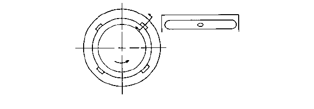
Elliptical and Lobe Bearings Elliptical and lobe bearings have noncircular geometries.
Figure 8 shows two types of three-lobe bearings with the clearance distribution exagger-
ated so that the lobe geometry is easily discernible. An elliptical bearing is simply a two-
lobe bearing with the major axis along the horizontal axis.
The lobe bearing shown in Figure 8a is a symmetric lobe bearing where the minimum
concentric clearance occurs in the center of each lobed region. Thus, at the leading edge
region, a converging clearance produces positive pressure, but downstream from the min-
imum film thickness, a divergent film thickness distribution can be found with resulting
negative, or cavitation, pressures.
The canted lobe in Figure 8b, on the other hand, generally develop positive pressure
throughout the lobe because the bearing is constructed with a completely converging film
thickness in each lobed region.This design has excellent whirl resistance (superior to that
of the symmetric lobe bearing) and a reasonably good load capability. A 2:1 ratio between
leading and trailing edge concentric clearance is generally a reasonable compromise with
respect to performance.
Elliptical and lobe bearings are often used because they provide better resistance to whirls
than cylindrical configurations. They do so because they have multiple load-producing pads
that assist in preventing large-attitude angles and cross-coupling (see the section on bearing
dynamics). Elliptical and lobe bearings are generally used for high-speed, low-load applica-
tions where whirls might be a problem.
2.256 CHAPTER 2
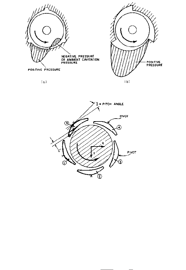
FIGURE 9 Five-pad tilting pad bearing.
FIGURE 8 (a) symmetric lobe bearing and (b) canted lobe bearing.
Elliptical, or two-lobe, bearings generally have poor horizontal stiffness because of the
large clearances along the major diameter of the ellipse. The split elliptical configuration,
however, is easier to manufacture than the other types because it is two cylindrical bear-
ing halves with material removed along the parting line. Lobe bearings are usually clear-
ance- and tolerance-sensitive. The other types of lobe bearings are complicated to
manufacture.
Tilting-Pad Bearings Tilting-pad bearings are used extensively, especially in high-
speed applications, because of their whirl-free characteristics. They are the most whirl-
free of all bearing configurations.
An important geometric variable for tilting-pad bearings is the preload ratio, defined
as shown in Figure 9.
The preload ratio equals
(24)
where c machined clearance
c¿ concentric pivot film thickness
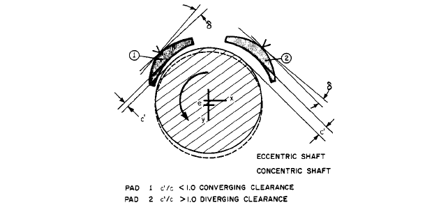
The variable c¿ is an installed clearance and is dependent upon the radial position of
the pivot. Figure 10 displays two pads. Pad 1 has been installed such that the preload ratio
Preload ratio PR
c c¿
c
1
c¿
c
2.2.5 CENTRIFUGAL PUMP OIL FILM JOURNAL BEARINGS 2.257
FIGURE 10 Tilting-pad bearing preload.
is less than one. For pad 2, the preload ratio is one. The solid line represents the position
of the journal in the concentric position. The dashed portion of the journal represents its
position when a load is applied to the bottom pads (not shown). Pad 1 is operating with a
good converging wedge, even though the journal is moving away from it. Pad 2, on the
other hand, is operating with a completely diverging film, which means that it is totally
unloaded. Thus, bearings with installed pad preload ratios of one or greater will operate
with unloaded pads, which reduces overall stiffness of the bearing and results in a deteri-
oration of stability because the unloaded pads do not aid in resisting cross-coupling influ-
ences. In the unloaded position, they are also subject to flutter instability and to a
phenomenon known as leading edge lockup, where the leading edge is forced against the
shaft and is maintained in that position by the frictional interaction of the shaft and the
pad. This is especially prevalent in bearings that operate with low-viscosity lubricants,
such as gas or water bearings. Thus, it is important to design bearings with preload,
although for manufacturing reasons it is common practice to produce bearings without
preload.
Tilting-pad bearings have some other characteristics that are both positive and negative:
• They are not as clearance-sensitive as most other bearings.
• Because the pads can move, they can operate safely at a lower minimum film thickness
than other bearings.
• They do not provide as much squeeze film damping as rigid configurations.
• Generally, they are more expensive than other bearings.
• For high-speed applications, their pivot contacts can be subjected to fretting corrosion.
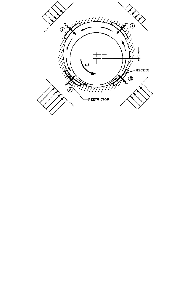
Hybrid Bearings A hybrid bearing, schematically shown in Figure 11, derives a load
capacity from two sources: (1) the normal hydrodynamic pressure generation and (2) an
external high-pressure supply that introduces oil into recesses machined into the bearing
surface via restrictors (orifices or capillaries upstream of the recesses). External pressure
significantly enhances load capacity. Also, these bearings have excellent low- or zero-speed
load capabilities. They are sometimes used as startup devices to lift off the rotor. When
self-sustaining hydrodynamic speeds are attained, the external pressure is shut off. The
characteristics of externally pressurized, or hybrid, bearings include the following:
• High load and stiffness capabilities
• An external flow that assists in cooling
2.258 CHAPTER 2
FIGURE 11 Cross-coupling influences in hybrid bearings.
• Their clearances and tolerances are generally more liberal than in hydrodynamic bearings
• They require external fluid-supply systems
• They are applied when there is not a sufficient generating speed or when a high-load
capacity and stiffness are required
• They are sometimes applied to prevent a whirl, but rotational speeds can unbalance
recess pressures, introduce cross coupling, and promote a whirl.
STEADY STATE PERFORMANCE________________________________________
Computer-generated performances have been obtained for most of the bearing types pre-
viously discussed. Information has been plotted in a nondimensional format so that no
restrictions exist on operating conditions, lubricant properties, and so on. Use of the charts
will be subsequently demonstrated by numerical example.
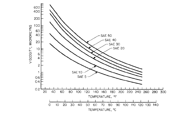
Viscosity One of the key parameters in determining the performance of a bearing is
the lubricant viscosity. Viscosity characteristics of commonly used Society of Automotive
Engineers (SAE) grades of oil are shown in Figure 12. The units of viscosity are
microreyns, where the reyn has the units of lb s/in
2
and comes from the ratio of shear
stress to the velocity gradient across the film, as indicated by Equation 21. Other units of
viscosity are centipoises, Saybolt seconds universal (SSU), and centistokes. The conversion
factors are as follows:
(25)
(26)
(27) Z1centiposes2 n1centistokes2 SG 1sp. gr.2
n1centistokes2 0.22 1SSU2
180
SSU
m1reyns2 Z 1.45 10
7
2.2.5 CENTRIFUGAL PUMP OIL FILM JOURNAL BEARINGS 2.259
FIGURE 12 Viscosity characteristics for SAE oil grades.
Performance Curves Performance plots have been generated for the following types of
bearings:
• Two-groove cylindrical bearings
• Symmetric three-lobe bearings: Each lobe is offset such that in the concentric position
the minimum film thickness in the center of each lobed region is half the machined
clearance c (see definition following). The pads are each 110° in the angular extent.
• Canted three-lobe bearing: The lobing is canted such that in the concentric position the
leading edge clearance was twice the trailing edge and the trailing edge film thickness
(minimum) in the concentric position was 0.5c where c equals the machined clearance.
The pads are each 110° in the angular extent.
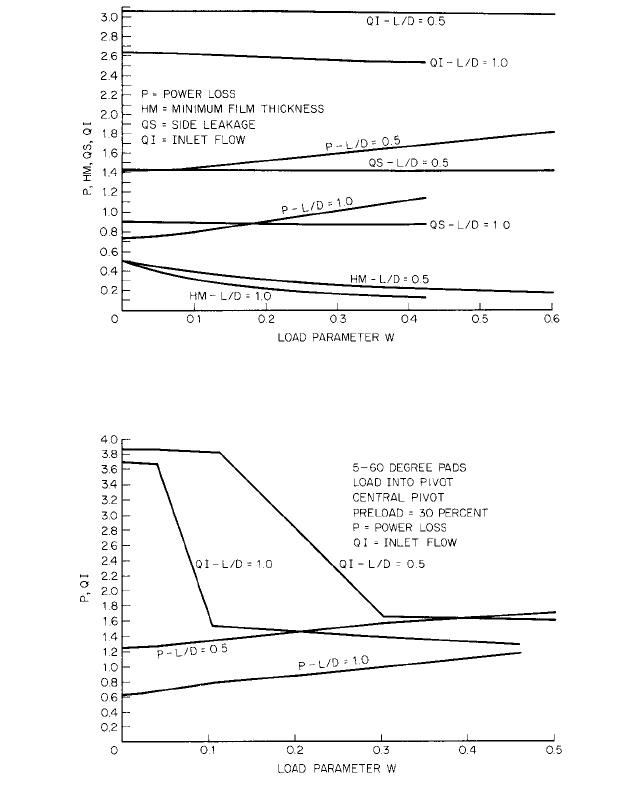
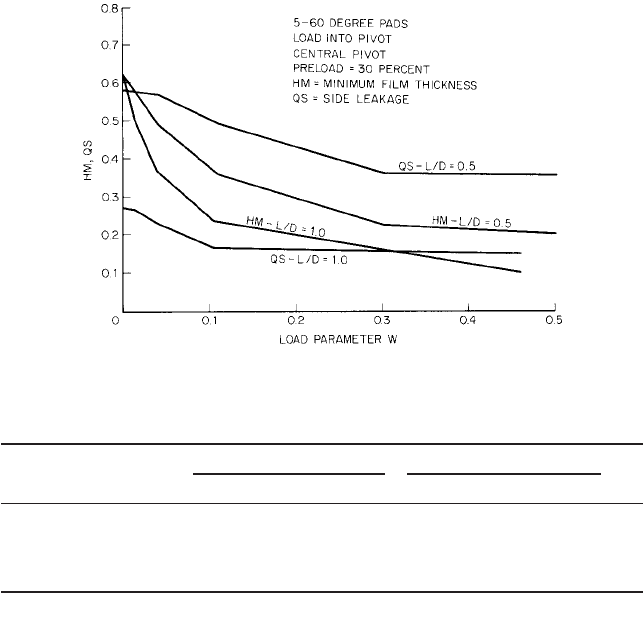
• Tilting-pad bearing: The tilting-pad bearing that information is obtained for is a five-
pad bearing with a 60° pad and a preload ratio of 30 percent.
Two length/diameter ratios are examined for each type of bearing: L/D 0.5 and 1.0.
The definition of the nondimensional parameters is as follows:
(28)
(29)
(30)
(31)
where w bearing load capacity, lb (N) and
c reference clearance (machined clearance radius of bearing radius of
shaft), in (mm)
m absolute viscosity, reyns (lb s/in
2
) (cP)
v shaft or journal rotational speed rad/s
R shaft radius, in (mm)
L bearing length, in (mm)
p viscous power loss, hp (kW)
q flow, gpm (m
3
/h)
HM nondimensional minimum film thickness h
M
>c
Q nondimensional flow parameter 2q>0.26vRLc
P nondimensional viscous power loss parameter 1100cp>m1vRL2
2
W nondimensional load parameter wc
2
>6mvRL
3
2.260 CHAPTER 2
FIGURE 13 Performance characteristics for two-groove cylindrical bearings.
FIGURE 14 Performance characteristics for three-lobe bearings.
q
i
inlet flow to the leading edge of bearing (for multipad bearings, equals the
sum of inlet flow to each pad), gpm (m
3
/h)
q
s
side leakage flow or flow out of the bearing ends (for multipad bearings,
equals the sum of side leakage flow of each pad), gpm (m
3
/h)
h
M
minimum film thickness in bearing, in (mm)
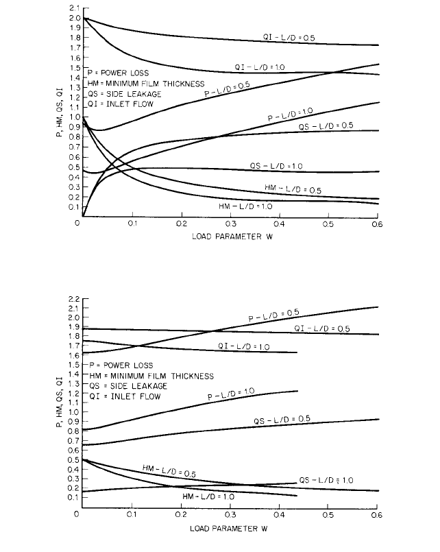
Performance curves are shown in Figures 13 through 17.
At times, the nondimensional data can be confusing and lead to erroneous judgments.
For example, the nondimensional power loss P is greater for an L/D equal to 0.5 than for
an L/D equal to 1.0. However, when the dimensional value of the power loss is being com-
puted, the nondimensional value is multiplied by L
2
. Therefore, the power loss for the L/D
2.2.5 CENTRIFUGAL PUMP OIL FILM JOURNAL BEARINGS 2.261
FIGURE 15 Performance characteristics for canted three-lobe bearings.
FIGURE 16 Performance characteristics for tilting-pad hearings.
equal to 1.0 will be, as expected, greater than for the L/D equal to 0.5. If the reader uses
the data as presented, the dimensional information will prove consistent.
To make comparisons among the bearings, using the nondimensional data is not
strictly proper because there may be slight inconsistencies in preloads, the bearings will
not be operating at the same average viscosity, and so on. Subsequently, dimensional data
derived from the performance curves will be compared, but comparisons of the nondi-
mensional information will provide an indication of performance parameters among the
bearings. Comparisons have been made at equal values of the load parameter W and the
results are shown in Table 1.
Comparisons of the different bearing types should be made only at the same L/D ratio
because of the anomalies (discussed above) of nondimensional parameters that occur at
2.262 CHAPTER 2
FIGURE 17 Performance characteristics for tilting-pad hearings.
TABLE 1 Comparative Results of Bearing Types at W 0.2
L/D 0.5 L/D 1
Bearing type P HM QS QI P HM QS QI
Two-groove cylindrical 1.13 0.36 0.78 1.81 0.72 0.25 0.50 1.50
Three-lobe 1.80 0.32 0.79 1.85 1.05 0.22 0.22 1.65
Canted three-lobe 1.52 0.31 1.42 3.30 0.91 0.22 0.90 2.58
Tilting-pad 1.50 0.30 0.44 2.82 0.90 0.20 0.16 1.50
QI nondimensional inlet flow 2qi/0.26 wRLc
QS nondimensional side leakage flow 2q
s
/0.26 wRLc
different L/D ratios. If we assume that all the reference variables that go into the nondi-
mensional parameters are identical, we can establish the following conclusions:
• The two-groove cylindrical hearing has the highest film thickness and thus the highest
load capacity.
• The symmetric three-lobe bearing has the highest power loss.
• The canted three-lobe bearing has the greatest flow requirements.
Note that these comparisons were made on the basis of steady-state performances
only. The major reason for applying lobe and tilting-pad bearings is to avoid dynamic
instabilities.
Heat Balance Performance is based upon the assumption of a uniform viscosity in the
fluid film. Since the viscosity is a strong function of temperature and since the tempera-
ture rise of the lubricant due to viscous heat generation is not known a priori, an itera-
tive procedure is required to determine the average viscosity in the film. To determine an
average viscosity, there must be a simplified heat balance in the film. The assumption is
made that all the viscous heat generated in the film is absorbed by the lubricant as it flows
through the film and produces a temperature rise.