Pump Handbook by Igor J. Karassik, Joseph P. Messina, Paul Cooper, Charles C. Heald - 3rd edition
Подождите немного. Документ загружается.

2.2.4 CENTRIFUGAL PUMP INJECTION-TYPE SHAFT SEALS 2.243
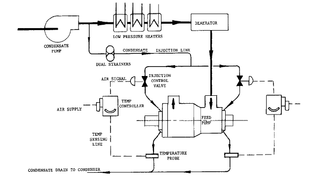
FIGURE 3 Temperature-controlled system regulating condensate injection to feed pump shaft seals
Constant Drain Temperature-Controlled System The constant drain temperature-
controlled seal system (see Figure 3) controls hot out-leakage by throttling the injection
flow to maintain a preset seal drain temperature. This system has a temperature-sensing
probe in each seal drain line. Each probe is connected to an indicating temperature con-
troller, which provides an air signal to a pneumatic control valve in the condensate injec-
tion line for control of the seal injection flow rate. Electronic control systems are often used
where thermocouples or RTD’s sense drain temperatures. The signal output is then
processed through an I/P controller that adjusts the position of the pneumatically operated
throttle valve as required.
The cold condensate is injected into the stuffing box central portion and allowed to mix
with hot water entering the seal from inside the pump. The drain temperature is main-
tained at a preset 140 to 150°F (60 to 66°C) to preclude flashing in the stuffing box or in
the drains. Note that with this system some hot water enters the seal.Therefore, cold con-
densate does not enter the hot pump and does not adversely affect pump warming condi-
tions, especially during extended idle periods. The required condensate injection pressure
is at least equal to the internal stuffing box pressure plus interim frictional loss between
the condensate supply source and the point of hot-water mixture. Note that this system
may enable satisfactory operation even when the condensate supply pressure is nearly
equal to boiler-feed pump suction pressure. In addition to providing a rapid response to
variations in operating pump conditions, this type of control will always supply just
enough injection water to maintain the recommended drainage temperature.
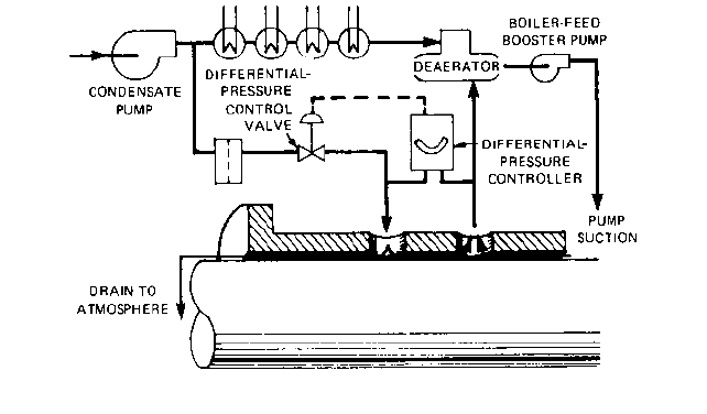
Intermediate Leakoff System The intermediate-leakoff shaft seal system (see Figure
4) has many variations but basically uses a bleedoff from a central portion of the stuffing
box. This system may be used to reduce internal stuffing box pressure if high boiler-feed
pump suction pressure exists. To create a positive leakoff flow, the intermediate bleedoff
flow is piped back to a plant feedwater system low-pressure point, such as a plant con-
denser, heater, or booster pump suction where the pressure is less than the boiler-feed
pump suction pressure. However, the back pressure of the leakoff destination must be
above the bleedoff vapor pressure to suppress flashing in the leakoff lines.This back pres-
sure may be the leakoff destination pressure or may be created by an orifice or a valve.
Cold condensate injection into the stuffing box is controlled by a pressure differential
monitor maintaining a preset pressure above the bleedoff pressure (refer to Figure 4). A
2.244 CHAPTER 2
FIGURE 4 Typical intermediate-leakoff shaft seal system. (From Power, September 1980, McGraw-Hill, New
York, copyright 1980)
stuffing box drain temperature control can also be used. Note that the cold condensate
injection pressure need not equal or overcome a high feed pump suction pressure.The con-
densate injection temperature must still be 85 to 110°F (30 to 45°C) to keep the drain tem-
perature below the flashing condition. Condensate injection shaft seals without an
intermediate bleedoff but that are subject to suction pressures in excess of about 250 lb/in
2
(1725 kN/m
2
) must be extremely long for a proper pressure breakdown. Longer shaft seals
require thicker pump case end covers, affecting pump cost, and a longer rotating element,
which could adversely affect rotor dynamics. The intermediate-leakoff shaft seal is effec-
tive where there is high feed pump suction pressure imposed by boiler-feed booster pumps
or in a closed feedwater system with no deaerating open heater, wherein a condensate
pump discharge can be fully imposed on the feed pump at low plant loads.
In plant systems with feedwater heaters between a booster pump and a feed pump, a
high pressure condensate from the cooler booster pump is injected into the seal to enable
a cooler intermediate leakoff to help prevent flashing (refer to Figure 2).
INJECTION SOURCES ________________________________________________
Many power plant feedwater systems with deaerating direct-contact heaters (open cycle)
usually have the boiler-feed pump drawing water directly from the deaerator. These open
cycles with constant-speed condensate pumps always have cold condensate supply pres-
sures in excess of boiler-feed pump suction pressure because of the increased available
condensate pump head at low system flows and the interim system frictional loss at high
system flows.
If a boiler-feed booster pump or a closed feedwater system with no open heaters and
resultant higher boiler-feed pump suction pressures is used, the pump manufacturer may
elect to require condensate injection seal water booster pumps or may use an intermediate-
leakoff packless shaft seal with a condensate injection overcoming only the intermediate
leakoff pressure. If the condensate pumps are variable-speed units that enable the con-
densate injection pressure to drop to an equal feed pump suction pressure at low loads with
little or no feedwater system frictional drop, then condensate injection seal water pumps
are required. In this situation, at least one pump manufacturer offers an optional pumping
2.2.4 CENTRIFUGAL PUMP INJECTION-TYPE SHAFT SEALS 2.245
ring configuration in their packless seal that can increase the seal water pressure in the
stuffing box to overcome any pump suction pressure.
AUXILIARY EQUIPMENT_______________________________________________
The condensate injection piping should be conservatively sized based on the maximum
injection flow requirements to obtain a low pressure drop between the injection source and
the seal injection control valve. These control valves may be equipped with limit stops to
prevent full closure and enable a continuous cool injection to the seals under almost all
operating conditions. In some installations, isolating lines are furnished around the valves
to enable a continued injection flow even during control valve maintenance.The valves can
also be designed to remain open during a failure, such as a loss of station air to the pneu-
matic controls, and to close only with an air supply. Injection control systems that are not
properly maintained might result in cold water entering a hot pump. Should this problem
occur while a boiler feed pump is in the hot standby mode or when turning gears, thermal
gradients will occur, leading to contact among the close running fits within the pump.
Proper maintenance and operation of the injection control systems is necessary to ensure
reliable operation of the pump itself. The air supply filter regulators for each control must
be furnished with relatively dry clean air at station supply pressure.
The condensate injection supply to the seals must be clear and free of foreign matter
to prevent damage to stuffing box components. It is therefore necessary to install filters in
the injection line prior to the control valve. To keep damaging fine mill scale, oxide parti-
cles, abrasives, and other materials from entering the small seal clearances, several pump
manufacturers recommend 100-mesh (150-micron) dual strainers. If dual strainers with
isolating valves are used, each filter can be cleaned without interrupting injection flow
during pump operation. Pressure gages should be installed before and after each filter to
permit the operator to monitor filter pressure drop. A differential pressure switch and
alarm for each filter are preferable to alert the operator to clean the strainer when pres-
sure drop becomes excessive.
The condensate injection shaft seals should always be filled with cool water before and
during pump operation, even during reverse pump rotation. Some pump manufacturers
stipulate that condensate injection must be continuous without any interruption during
all operation modes.
The clearances in the condensate injection shaft seal may double over the service life
of the internal wearing parts.With double clearances, the leakage will approximately dou-
ble.This factor should be considered when sizing the return drain piping back to the plant
condenser if frictional losses are to be kept to a minimum. The drain line should be pitched
at least a quarter-inch per foot (20 mm per meter). The collecting chamber at the pump
stuffing box is vented to the atmosphere, and the only head available to evacuate the
chamber is the static head between the pump and the point of return. This head must
always be well in excess of the frictional losses (even after the leakage is doubled). Other-
wise, the drains may back up, the collection chambers may overflow, and the adjacent
bearing brackets may flood, with subsequent possible intrusion of water into the pump
bearings and lubricating oil.
The seal collection chambers have especially large connections to assure proper
drainage, provided no back pressure exists. Two types of condensate drain systems can be
used to dispose of the drain coming from the collecting seal chambers. One system uses
traps that are piped directly to the plant condenser if sufficient static head exists for pos-
itive drain flow. The second system collects the drain in a condensate storage tank into
which various other drains (from other pumps shaft seals and so on) are also directed. As
this vented storage tank is under atmospheric pressure, it must be set at a reasonable ele-
vation below the pump centerline so that the static elevation difference will overcome fric-
tional losses in the drain piping. A separate condensate transfer pump, under control of
the storage tank liquid level control system, can then pump the condensate drains from
the storage tank into the plant condenser. The storage tank should have its own overflow
2.246 CHAPTER 2
protection system that enables outside drainage if, for some reason, proper drainage can-
not be achieved. For example, the top of the tank vent pipe should be below the pump cen-
terline to help preclude the possibility of drainage backing up to the level of the pump seal
collection chambers. Note that this storage tank should also be large enough for an ade-
quate drainage collection to help prevent backups.
PACKLESS SHAFT SEALS WITHOUT INJECTION __________________________
The packless shaft seals that have been so successfully applied to boiler-feed, reactor-feed,
and booster pump services are applicable to a number of other services. For instance, they
are very suitable for cold-water condensate booster pumps and for high-pressure pumps
applied to hydraulic descaling or hydraulic press work. In such services, there is no need
to bring in an injection supply water to the breakdown seals (unless the pumped water is
not clear and free of gritty material), because the water handled by the pump is already
cold with no danger of flashing as it leaves the pump stuffing boxes.
2.2.5
CENTRIFUGAL PUMP OIL FILM
JOURNAL BEARINGS
WILBUR SHAPIRO
2.247
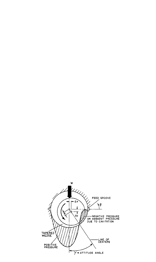
FIGURE 1 Two-groove cylindrical bearing.
PRINCIPLES OF OPERATION___________________________________________
A journal bearing is essentially a viscous pump, and it derives load capacity by pumping
the lubricant through a small clearance region. In Figure 1, the fluid is dragged along by
2.248 CHAPTER 2
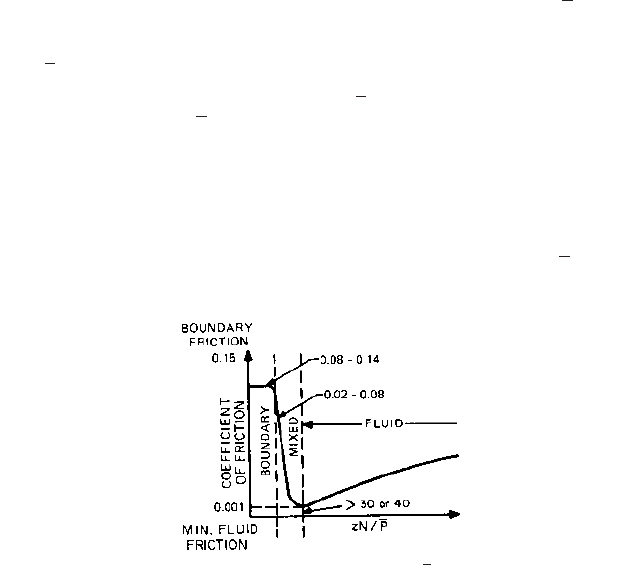
FIGURE 2 Coefficient of friction versus (Ref. 1).ZN>P
*1 bar 10
5
Pa. For a discussion of bar, see “SI Units:A Commentary” in the front matter.
the rotating journal. To generate pressure, the resistance to pumping must increase in the
direction of the flow. In the figure, the journal moves to form a converging tapered clear-
ance in the direction of the rotation or flow.
The eccentricity e is the total displacement of the journal from its concentric position.
The attitude angle g in Figure 1 is the angle between the load direction and the line of cen-
ters. Note that, because of the necessity to form a converging wedge, the displacement of
the journal is not along a line that is coincident with the load vector. A positive pressure
is produced in the converging region of the clearance. Downstream from the minimum film
thickness, which occurs along the line of centers, the film becomes divergent. The resis-
tance decreases in the direction of pumping, and either negative pressures occur or the air
in the lubricant gasifies or cavitates and a region of atmospheric pressure occurs in the
bearing area. This phenomenon is known as fluid film bearing cavitation. It should be
clearly distinguished from other forms of cavitation that take place in pumps, such as in
the impeller, for example. Here the fluid is traveling at a high velocity and the inertia
forces on each fluid element dominate. Implosions occur in the impeller and can cause
damage.
In a bearing, the viscous forces dominate and each fluid particle moves at a constant
velocity in proportion to the net shearing forces on it. Thus, cavitation in a bearing is more
of a change of the phase of the lubricant that occurs in a region of lower pressure that per-
mits the release of entrained gases. Generally, bearing cavitation does not cause damage.
Regimes of Lubrication Whether or not a fluid film can be formed, journal rotation is
dependent on several factors including the surface speed, viscosity, and load capacity. A
parameter
1
is often used to determine a particular regime of lubrication, , where
Z viscosity of lubricant, cP (Pa s)
N rotating speed, rpm
, average pressure of the bearing, lb/in
2
(bar)*
A plot of the coefficient of friction versus generally has the form shown in Fig-
ure 2. At low values of , a combination of viscosity, speed, and load places a bearing
in a boundary lubricated regime where typical coefficients of friction are 0.08 to 0.14.
Boundary lubrication implies intimate contact between the opposed surfaces.As the value
of the parameter increases as a result of the increased speed, increased viscosity, or low-
ered load, there is a dramatic reduction in the coefficient of friction. In this region, there
is a mixed film lubrication and the coefficient of friction varies between 0.02 and 0.08. By
mixed film lubrication, it is meant that the journal is partly surrounded by a fluid film and
is partly supported by rubbing contact between the opposed members.As increasesZN>P
ZN>P
ZN>P
P
ZN>P
2.2.5 CENTRIFUGAL PUMP OIL FILM JOURNAL BEARINGS 2.249
further, a situation of full fluid film lubrication prevails.
A general rule of thumb is that should be 30 (0.44) or greater for a fluid film to
be generated. Note that as continues to increase beyond the full film demarcation,
the coefficient of friction rises, but at a relatively low rate and generally remains in regions
of low coefficients of friction.
EXAMPLE
The bearing is not fluidborne and is operating in the mixed film regime. At what
speed will the bearing become hydrodynamic? For hydrodynamic operations, 30.
Therefore,
THEORETICAL FOUNDATIONS _________________________________________
The foundation of a fluid film-bearing analysis emanates from the boundary layer theory
of fluid mechanics. The governing differential equation was first formulated by Osborne
Reynolds in 1886 and is known as Reynolds’ equation in his honor. It has been only in the
last 30 years or so that general solutions have been obtained, and this has been primarily
due to the use of numerical methods applied to the digital computer. References 2 and 3
go into the details of contemporary numerical solutions and are recommended for those
interested in the analytical aspects of lubrication.
Principal Assumptions Reynolds’ equation can be derived from the Navier-Stokes
equation of fluid mechanics, and a number of textbooks are available that comprehen-
sively describe the derivation.
4
The primary assumptions are as follows:
• Laminar flow conditions prevail, and the fluids obey a Newtonian shear stress
distribution where the shear stress is proportional to the velocity gradient.
• Inertial forces, resulting from acceleration of the liquid, are small relative to the viscous
shear forces and may be neglected.
• The pressure across the film is constant since the fluid films are so thin.
• The height of the fluid film is small relative to other geometric dimensions, and so the
curvature of the fluid film can be ignored.
• The viscosity of the liquid remains constant. In most cases, this is a reasonable assump-
tion since it has been repeatedly demonstrated that, if the average viscosity is used, lit-
tle error is introduced and the complexity of the analysis is considerably reduced.
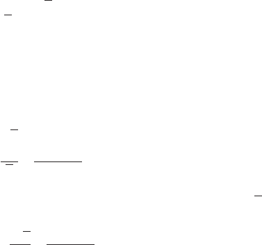
Derivaton of Reynold’s Equation of Lubrication Assume that the rotating journal
has a peripheral velocity U. Consider an elemental volume in the clearance space of the
bearing and establish equilibrium (see Figure 3). Note that since inertial forces are
neglected, the volume is in equilibrium by the pressure and shear forces acting upon it,
so there is no acceleration. As shown in Figure 4, p is the pressure and t is the shear stress
acting upon the volume. Summing forces in the x direction
N
30P
Z
30 200
30
200 rpm
ZN>P
ZN
P
30 150
200
22.5
P 200 lb>in
2
113.6 bar2
N 150 rpm
Z 30 cP 10.03 Pa
#
s2
ZN>P
ZN>P
2.250 CHAPTER 2
FIGURE 3 Fluid control volume.
FIGURE 4 Force equilibrium on fluid element.
FIGURE 5 Laminar velocity distribution across film.
(1)
or
(2)
For a Newtonian fluid in a laminar flow, the shear stress is directly related to the veloc-
ity gradient with the proportionality constant being the absolute viscosity m (see Figure 5):
(3)
where n is the fluid velocity. Substituting Equation 3 into Equation 2, we obtain
(4)
Integrating with respect to y twice produces the following equation:
(5)
where C
1
and C
2
are constants of integration. The boundary conditions are
(6)
Substituting the boundary conditions of Equation 6 into Equation 5 results in the fol-
lowing expression for y:
(7)v
1
2m
0p
0x
1y
2
h
2
y2
uy
2
v u, y h
v 0, y 0 and
v
1
m
0p
0x
y
2
2
C
1
y C
2
0p
0x
m
0
2
v
0y
2
0t
0y
m
0
2
v
0y
2
t m
dv
dy
0p
0x
0t
0y
0p
0x
dx dy dz
0t
0y
dx dy dz 0
p dy dz
a
p
0p
0x
dx
b
dy dz t dx dz
a
t
0t
0y
dy
b
dx dz 0
2.2.5 CENTRIFUGAL PUMP OIL FILM JOURNAL BEARINGS 2.251
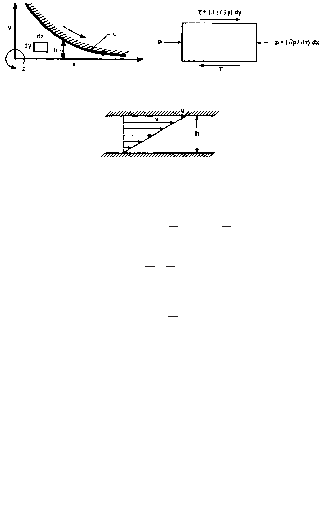
FIGURE 6 Flow balance across control volume.
The velocity in the z direction would be similar, except that the surface velocity term
would be omitted because no surface velocity exists in the z direction. In addition, the pres-
sure gradient would be with respect to z.
Now let us consider the flow across the film due to this velocity. Note that Equation 7 is
the velocity computed in the x direction, which is in the direction of rotation of the journal:
(8)
After integrating,
(9)
Note that q
x
is the flow per unit width across the film. The flow in the axial direction is
(10)
Now let us consider a flow balance through an elemental volume across the film (see
Figure 6). The net outflow through the volume equals the net reduction in volume per
unit time:
(11)
Thus, this gives us
(12)
Substituting Equations 9 and 10 into Equation 12, we obtain
(13)
and the final equation becomes
(14)
Equation 14 is the general form of Reynolds’ equation used for laminar, two-
dimensional lubrication problems.
Reynolds’ equation is a flow balance equation. The left-hand side represents pressure-
induced flows in the x and z directions through the differential element. The first term on
the right-hand side represents the shear flow of the fluid induced by the surface velocity
of the journal u. Note that this term contains the derivative of clearance with respect to
distance. If this term is zero, then there is zero pressure produced by hydrodynamic action,
0
0x
a
h
3
m
0p
0x
b
0
0z
a
h
3
m
0p
0z
b 6m
0h
0x
12
0h
0t
0
0x
a
1
12m
h
3
0p
0x
b
0
0z
a
1
12m
h
3
0p
0z
b
0h
0t
u
2
0h
0x
0q
x
0x
0q
z
0z
0h
0t
aq
x
0q
x
0x
dxb dz q
x
dz aq
z
0q
z
0z
dzb dx q
z
dx
0h
0t
dx dz
q
z
1
12m
0p
0z
h
3
q
x
1
12m
0p
0x
h
3
1
2
uh
q
x
h
0
v
x
dy
h
0
c
1
2m
0p
0x
1y
2
h
2
y2
uy
2
ddy
2.252 CHAPTER 2
and the term 0h/0x is the mathematical representation of the tapered wedge. The second
term on the right-hand side refers to a time rate of change of the film thickness, which can
be translated to a normal velocity of the center of the journal. It produces pressure by a
fluid velocity normal to the bearing surfaces that attempts to squeeze fluid out of a
restricted clearance space. This phenomenon is called the squeeze film effect in bearing
terminology. Since it is proportional to the velocity of the center of the journal, it is the phe-
nomenon that produces viscous damping in a bearing.
The solution to Reynolds’ equation (refer to Equation 14) provides the pressure at all
points in the bearing.The application of the digital computer has enabled a rapid solution
of Reynolds’ equation over a grid network representing the bearing area.
2,3
Once the pressures have been obtained, a numerical integration is applied to deter-
mine the performance parameters (in other words, the load capacity):
(15)
The flow across any circumferential line is
(16)
The flow across any axial line is
(17)
The viscous frictional moment is obtained by integrating the shear stress over the area
and can be shown to be
(18)
where v journal surface speed, rad/s.
Typical computer program output includes the following:
• Pressure distribution throughout the grid network
• Load capacity
• Side leakage and carryover flows
• Viscous power losses
• Righting moments due to misalignments
• Attitude angles
• Cross-coupled spring and damping coefficients due to displacements and velocity per-
turbations of the journal center
• Clearance distribution
Turbulence Equation 14 is for laminar conditions. For very high speed bearings, oper-
ations beyond the turbulent regime may occur and Reynolds’ equation must be modified.
The turbulent theory has been developed, and the literature on this topic can enable per-
formance predictions for turbulent bearings.
5,6
The onset of turbulence is determined by examining the bearing’s Reynolds number,
which is the ratio of inertia to viscous forces and is defined as
M
f
c
1
r
0p
0u
h
2
mrv
h
d r
2
du dz
qz
a
1
12m
0p
0z
h
3
b rdu
q
u
a
1
12m
0p
r0u
h
3
1
2
uhb dz
w
prdu dr