Pump Handbook by Igor J. Karassik, Joseph P. Messina, Paul Cooper, Charles C. Heald - 3rd edition
Подождите немного. Документ загружается.

2.2.6 CENTRIFUGAL PUMP MAGNETIC BEARINGS 2.283
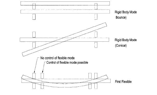
FIGURE 9 Flexible mode design considerations
There is an area where careful analysis is needed for each new pump configuration.A con-
ventional bearing, if overloaded, will accept the load with a higher wear rate, but a magnetic
bearing has a sharp cut-off at the point where the flux saturation level is reached. At that
point, any additional load will be transferred to the catcher bearing. Thus it is important to
include all loads in the design specification, with the appropriate margins.All applications to
date have generally shown a) that there are loads which were mistakenly considered to be
insignificant, or b) that the values of the loads were underestimated due to lack of knowledge.
Magnetic bearings also must be carefully designed to handle transient loads, some of
which may occur only once in a lifetime. Two approaches can be taken. One is to over-
design the bearing to handle the load without contacting the catcher bearing; the other is
to allow momentary contact with the catcher bearing. Examples of these types of loads are
hydraulic loads, seal touchdown loads, system loads such as water hammer, valve opera-
tion, pump switchover, pump to driver alignment loads, and seismic loading.
Rotordynamics Considerations Magnetic bearings have the capability to control the
rotor dynamics of a pump very effectively. If the pump is running below its first flexible
mode, this is usually straightforward. If the pump has to traverse a flexible mode, the posi-
tion of the bearings and the position sensor must be such that the modes can be recog-
nized by the position sensor, and the bearings can exert a positive restoring force to control
the mode. That is, the position sensors and bearings must not be positioned at or close to
a node and certainly not positioned on opposite sides of a mode. Thus, rotordynamics con-
siderations should be taken care of very early in the configuration of the system.
The two typical rigid body modes are shown in Figure 9. The location of the bearing
and position sensor is not usually an issue for these modes, but the flexible modes require
that the position sensor and bearing be positioned in such a way that the rotor deflection
can be measured and the bearing can exert the necessary restoring force and damping to
control the mode.
Magnetic bearing controllers are programmed with a transfer function designed specif-
ically for the pump. This transfer function, or control algorithm, provides the necessary
stiffness and damping at all operating speeds to control the rotor as previously described.
The key requirements of the transfer function are that it
• Provides correct damping and stiffness to handle the rotor rigid body modes
• Provides sufficient force with the appropriate control bandwidth to handle the rotor flex-
ible modes below the maximum operating speed

2.284 CHAPTER 2
TABLE 2 Approximate magnetic bearing sizing relationships
Sizing Parameter Heteropolar Homopolar
Radial Bearings
a) Dimensions, in multiples of the shaft diameter
Air gap diameter, D 2 1.5
Stator outer diameter 4 3
Overall axial length 2 1.5
Active axial length of poles at air gap, L 0.9 0.8
b) Unit load capability, F
r
/DL, lb/in
2
(MPa) 40 (0.28)* 60 (0.41)
Axial Thrust Bearings
a) Diameter ratio D
i
/D
o
of active pole area 0.5 0.5
b) Unit load capability, F
z
/ [p(D
o
2
D
i
2
)], lb/in
2
(MPa) 50 (0.34)* 70 (0.48)
*Higher with special lamination material
• Does not excite any rotor modes above the maximum operating speed
• Does not excite any stator vibration modes at any frequency
• Takes into account the stiffness and damping contribution from wear rings and inter-
stage annular seals
Auxiliary or Catcher Bearings However reliable magnetic bearings become, a landing
surface for maintenance will be required. Further, designing a bearing that will take all
transient loads without any possibility of overload will usually result in over-sized and
costly bearings. Hence catcher, bearings are expected to be required. The design limits for
catcher bearings are usually established by calculating the forces that will result from a
drop at operating speed.
For applications running at significant speeds,a non-linear analysis is required to deter-
mine the motion and loading on the bearing during such a drop. The key design considera-
tions are impact loads, heat generation during the rundown, and the response to imbalance
if, when running on the catcher bearings, any critical speeds have to be traversed.
Rolling element bearings have typically been used as catcher bearings; however, sleeve
bearings and bushings have been used in several applications, and are better suited to a
submerged application.
MAGNETIC BEARING SIZING___________________________________________
The fundamental magnetic bearing sizing problem is to define the pole area at the bear-
ing air gap that is necessary to achieve the desired force capacity without saturating the
selected pole materials. Given the pole area, the minimum stator outside diameter and
maximum rotor inside diameter can be determined using simple algorithms to ensure that
no other part of the magnetic circuit saturates.The stator geometry must also include suf-
ficient volume for the control and bias coils.
Approximate size and load capability Table 2 contains rough approximations for the
dimensions of magnetic bearings. (Refer to Figure 1.) These are based on the experience
with the pumps of Table 1. Also included are the unit load capabilities, which are given
a) for radial bearings in terms of radial load F
r
divided by the projected area DL of the
active polar area of the bearing at the air gap, and b) for axial thrust bearings in terms
of the axial load F
z
divided by the active pole area of the runner disk between the inner
diameter D
i
and the outer diameter D
o
. These approximations provide the designer and
user with an idea of the design configuration of a magnetic-bearing-equipped pump. The
2.2.6 CENTRIFUGAL PUMP MAGNETIC BEARINGS 2.285
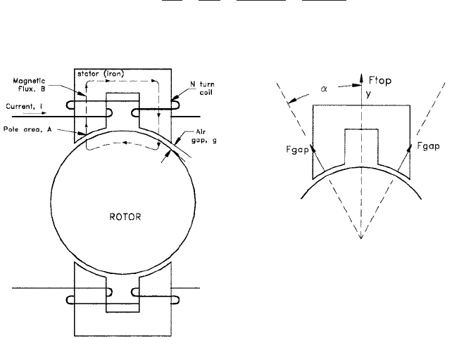
FIGURE 10 Simple electromagnetic circuit for one quadrant of a heteropolar magnetic bearing
low unit loads of magnetic bearings result in more space being needed for them in com-
parison to conventional bearings.
Theory of One-Dimensional Sizing To perform more accurate, in-depth sizing, the the-
ory of both heteropolar and homopolar magnetic bearings is applied. Magnetic bearing siz-
ing and geometry programs normally use simple one-dimensional magnetic circuit theory
to obtain initial sizing and perform design iterations. This initial sizing is then followed
up with design analysis using 2D or 3D magnetic FEA analysis to verify the design. The
basis of the classic one-dimensional sizing for a magnetic bearing is discussed next, first
for the heteropolar bearing and then for the homopolar bearing.
HETEROPOLAR BEARING
a. Magnetic circuit
—
The basic magnetic circuit equation, derived from Ampere’s Loop
Law, is
R (1)
where MMF magnemotive force
magnetic flux
R path reluctance
A sketch of one quadrant (one electromagnet) of a heteropolar bearing is shown in Fig-
ure 10.
Assuming the air gap area and path areas are equal, Eq. 1 becomes
(2)2Ni BA
a
g
m
o
A
g
m
o
A
l
stat
m
o
m
r, stat
A
l
rot
m
o
m
r, rot
A
b
MMF £

2.286 CHAPTER 2
Where N number of turns per pole
i coil current
B magnetic flux density
A pole area
g air gap
m
o
permeability of free space
m
r
relative permeability
l iron path length
If the iron permeability is high relative to the air gap (m
r, rot,
m
r, stat
77 m
o
), the iron reluc-
tance terms are insignificant and the following equation can be obtained for the flux:
(3)
b. Force calculation
—
The basic force equation for an air gap is
(4)
This equation assumes negligible leakage and fringing and that the flux density is uni-
form in the air gap. The combined vector force along the center of the bearing for the two
air gaps of the top magnet is
(5)
Substituting from Eq. 4 gives
(6)
If the saturation flux density, B
sat
, of the iron material is used for B, Eq. 6 defines the
load capacity as a function of pole area for a heteropolar magnetic bearing.
c. Linearization of the force/current characteristic
—
Substituting from Eq. 3 gives:
(7)
Thus, the force in a given magnet is proportional to the square of the current, a result
that makes the bearing more difficult to control. Additionally, a single electromagnet can
only apply a force in one direction (an attractive force). For these two reasons, opposed
electromagnets are used together with a bias current (or flux) in each coil.
The current relationship is
to increase the force,
to decrease the force.
The rotor may also be off-center in the air gap, described by
i i
bias
i
con
i i
bias
i
con
k
1
cos a AN
2
m
o
F
top
cos a
A
m
o
a
Nim
o
g
b
2
cos a AN
2
m
o
i
2
g
2
k
1
i
2
g
2
F
top
cos a
B
2
A
m
o
F
top
2F
gap
cos a
F
gap
B
2
A
2m
o
B
Nim
o
g
2.2.6 CENTRIFUGAL PUMP MAGNETIC BEARINGS 2.287
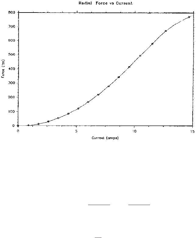
FIGURE 11 Force versus current for radial bearing of multistage pump
Applying Eq. 7 to both top and bottom electromagnets yields
(8)
With the rotor centered (y 0), this can be reduced to
(9)
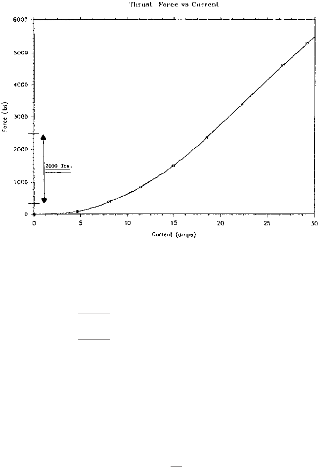
Thus the net bearing force is proportional to the control current. Figures 11 and 12 are
examples of measured force versus current for radial and axial thrust bearings respec-
tively. These measurements were made on the magnetic bearing of the multistage pump
in Table 1 (refer to Figures 1 and 2).
d. Force constant and negative stiffness
—
Eq. 8 can be also be linearized for small
motion about the center (y 66 g
0
) by differentiating with respect to i
con
and y, the
two quantities in Eq. 8 that can change in normal operation of the bearing. The
result is
(10)F
y
k
f
i
con
k
n
y
F
y
4
k
1
g
0
2
i
bias
i
con
F
y
F
top
F
bot
k
1
ca
i
bias
i
con
g
0
y
b
2
top
a
i
bias
i
con
g
0
y
b
2
bot
d
g g
0
y bottom air gap
g g
0
y top air gap
2.288 CHAPTER 2
FIGURE 12 Force versus current for axial thrust bearing of multistage pump
where
(11)
(12)
The position stiffness is the passive stiffness of the bearing with a bias field but with
no control current. The position stiffness is always negative, indicating that if the rotor is
displaced from center, it will be pulled further from its equilibrium position if no control
current is applied. The force constant defines the relationship of the control force to cur-
rent (lb/amp or N/amp) with the bearing centered. It is also negative, indicating that
applying a control current pulls the rotor from its centered position. Many practitioners
use positive values for the force constant and the position stiffness as a matter of conve-
nience. In this case, the minus signs in Eq. 10 become plus signs.
The control current is determined by the measured displacement, y, and the charac-
teristics of an adjustable sensor/compensator/amplifier transfer function:
(13)
Substituting Eq. 11 into Eq. 10 gives
(14)Fy k
F
G
con
1s2y k
n
y
G
con
1s2
i
con
y
k
n
4k
1
i
2
bias
g
3
0
negative stiffness or position stiffness
k
f
4k
1
i
bias
g
2
0
force constant or current stiffness

2.2.6 CENTRIFUGAL PUMP MAGNETIC BEARINGS 2.289
FIGURE 13 Control magnetic circuit for one axis of a homopolar magnetic bearing
The characteristics of the control transfer function G
con
(s) are determined in order to
stabilize the rotor/bearing system.
HOMOPOLAR BEARING In the homopolar bearing, a bias flux is used for linearization just
as in the heteropolar bearing; however, the bias flux and control flux follow different paths.
Additionally, the bias flux can be generated by either a permanent magnet (most common)
or an electromagnetic coil. The use of a permanent magnet for bias reduces power con-
sumption and makes the bearing more linear at large position offsets.
a. Magnetic control circuit
—
The control circuit for one half of the homopolar bearing,
shown in Figure 13, is across the top air gap, through the rotor, out the bottom air gap,
and around the back iron.
When Eq. 1 is applied to this circuit, the result is similar to Eq. 2:
(15)
Again, if the iron permeability is high relative to the air gap, this can be reduced to the
following:
(16)
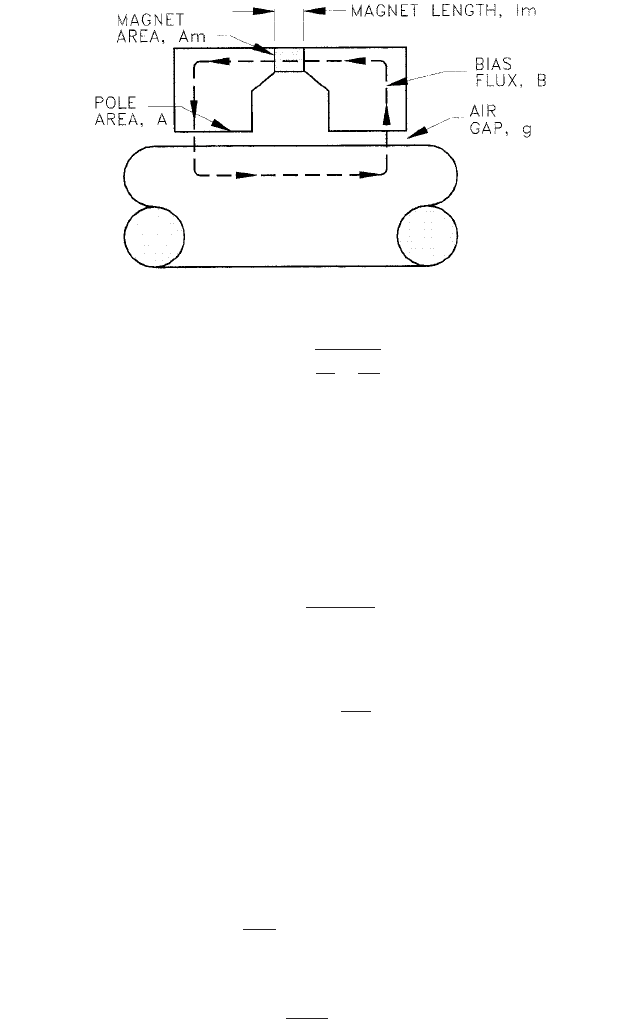
b. Magnetic bias circuit
—
The magnetic circuit equation for the bias circuit, shown in
Figure 14, is
(17)
Where B
r
residual induction of the magnet
l
m
axial length of the magnet
m
r, m a g
relative permeability of the magnet (1.0–1.05)
A
m
magnet cross-sectional area per quadrant
With the magnet permeability assumed to be 1.0, this can be reduced to
B
r
l
m
m
o
m
r, mag
B
bias
A
a
g
m
o
A
g
m
o
A
l
m
m
o
m
r, mag
A
m
b
B
con
Ni
con
m
o
g
2Ni
con
B
con
Aa
g
m
o
A
g
m
o
A
l
stat
m
o
m
r,stat
A
l
rot
m
o
m
r,rot
A
b
2.290 CHAPTER 2
FIGURE 14 Bias magnetic circuit for one quadrant of a homopolar magnetic bearing
(18)
c. Force calculation
—
The basic force equation for an air gap is given by Eq. 4. In the
homopolar bearing, the pole face covers a broader arc of the rotor than in the het-
eropolar bearing; therefore, the air gap force must be integrated over the surface to
obtain the desired vector force, F
top
. Both the front and back control stacks must also
be included. The result is
Where:
(19)
This result assumes negligible leakage and fringing and that the flux density is uni-
form in the air gap. Substituting from Eq. 4 into Eq. 19 gives
(20)
If the saturation flux density, B
sat
, of the iron material is used for B, Eq. 20 defines the
load capacity as a function of pole area for a magnetic bearing.
d. Linearization of the force/current characteristic
—
The air gap flux density in the
homopolar bearing is the superposition of the bias and control flux. The control coils
and permanent magnet polarity are arranged such that when the control flux adds
to the bias in the top air gaps, the control subtracts from the bias in the bottom air
gaps. Thus the net vertical force is
(21)
This can be reduced in a similar manner as before to produce
(22)F
y
4C
g
A
m
o
B
bias
B
con
F
y
F
top
F
bot
C
g
A
m
o
31B
bias
B
con
2
2
top
1B
bias
B
con
2
2
bot
4
F
top
C
g
B
2
A
m
o
C
g
2sin1u
a>2
2
u
a
F
top
2C
g
F
gap
B
bias
B
r
2g
l
m
A
A
m

2.2.6 CENTRIFUGAL PUMP MAGNETIC BEARINGS 2.291
Substituting from Eq. 16
(23)
Thus the control force is proportional to the control current as desired.
e. Force constant and negative stiffness
—
The expression given in Eq. 10 for the
heteropolar bearing also applies to the homopolar bearing:
(24)
The definition of the force constant is
(25)
The expression for negative stiffness is not easily reducible to analytical form due to
the complexity of the bias circuit. However, the existence of the permanent magnet in the
bias flux path as a fixed and large reluctance improves the linearity of this bearing for off-
center operation. Eqs. 13 and 14 for the heteropolar bearing apply to the homopolar bear-
ing as well.
INSTALLATION AND TUNING ___________________________________________
Mechanical Installation
Magnetic bearings have the advantage that they can be set,
by adjusting offsets in the controller, to center the rotor on the magnetic bearing stator,
the catcher bearing, the seals, or any other mechanical reference in the pump. The rotor
can even be offset vertically to cancel the effect of gravity, thus reducing static power
requirements to near zero. Careful consideration is needed during design to decide which
is the best approach.
The position sensors in the bearings can also be used to measure the clearances
between the rotor and any physical stops such as a sealing ring, without disassembly.
Tuning The rotor dynamics analysis performed during the early design stage will be
used to determine the initial controller compensation, which will have a transfer function
matched to the pump requirements. During initial testing, this transfer function will have
to be adjusted to match the as-built dynamics of the rotor and support structure.
Normally the rotor will be accurately modeled and little change will be needed. If there
are shrink fits or bolted joints, there may be some stiffness variation from the theoretical
model. This may require on-site controller compensation adjustment. However, the stator
is often a complex structure, and adjustments may be needed to avoid the excitation of sta-
tor modes.
DIAGNOSTICS AND USER INTERFACE __________________________________
Diagnostic Capabilities
The controller, in order to function, must analyze a continu-
ous stream of information on the shaft location in each of the five control axes, two for
each radial bearing and one for the thrust bearing. This information can be accessed for
external diagnostic use, as can the corresponding information on bearing current, from
which can be inferred the bearing load. This diagnostic information can be a very useful
source of information on the health of the pump, its mechanical components, and on the
system it is operating in.
k
f
4C
g
ANB
bias
g
0
force constant or current stiffness
Fy k
f
i
con
k
n
y
F
y
4C
g
AN
g
B
bias
i
con
2.292 CHAPTER 2
TABLE 3 Operating experience with multistage pump
Expected Load, lb (kN) Design Load, lb (kN) Actual Load, lb (kN)
Bearing Steady Transient Steady Transient
Radial 1,280 (1.2) 1,560 (2.5) 1,800 (3.6) 1,280 (1.2) 1,580 (2.6)
Axial 1,000 (4.4) 2,000 (8.9) 4,000 (17.8) 1,100 (4.9) 2,500 (11.1)
Interface Requirements The magnetic bearing system controller can also be interfaced
with the plant control system with the following type of logic:
• No drive unit start without levitation
• No delevitation at speed
• Rotor offset and bearing load alarms
• Rotor offset and bearing load driver trips, with possible time delay
RELIABILITY AND MAINTENANCE ______________________________________
Bearing Cartridges
As explained earlier, the reliability of the bearing stator and rotor
components should be such as to provide lifetime service.
Controller The main life limiting component in the controller is likely to be the ampli-
fier. In a redundant system, online replacement is possible without loss of levitation. In
a non-redundant system, a preventative maintenance approach should be used for this
component.
OPERATING EXPERIENCE _____________________________________________
Multistage Boiler Feed Pump
The multistage pump of Table 1 (refer to Figure 1) was
installed as one of three otherwise identical pumps (two in parallel, one standby) in an
electric utility generating plant (refer to Figure 2). The objective was to show that mag-
netic bearings would work in a typical field application of a pump of significant power
level. This project took the first step of replacing the conventional bearings in this 610 hp
(0.46 MW) eight stage centrifugal pump, which were outboard of the pump itself, and
replacing them with heteropolar active magnetic bearings without any major design
changes
6
. This was seen as the first of two steps, the second being a project where the bear-
ings would be submerged in the operating fluid, allowing one seal system to be replaced
8
.
As with many magnetic bearing projects, the main lesson learned was that the tran-
sient bearing loads could not always be predicted ahead of time, and that the magnetic
bearings gave very precise and important feedback of this information. Table 3 contains
the design and field data. In this case, the 2500 lb (11 kN) transient load occurred when
the plant underwent a suction pressure transient in which the available NPSH became so
low that the first stage of this horizontally-opposed staging configuration (refer to Figure
1) apparently lost pressure rise completely
6
. The axial thrust of this stage was accordingly
lost, destroying the intended axial hydrodynamic thrust balance of the pump. (See Sec-
tions 2.1 and 2.2.1.) Nevertheless, the conservative design of the thrust bearing enabled it
to accommodate this load.
Single-Stage Process Pump The 800 hp (0.6 MW) single-stage double-suction process
pump of size 8 26 (200mm 660mm) of Table 1 was retrofitted with homopolar
bearings
7
.
Closed-loop testing was conducted in the pump manufacturer’s facility (see Figure 15).
As indicated in Table 4, the results showed that a substantial operating margin exists for