Pump Handbook by Igor J. Karassik, Joseph P. Messina, Paul Cooper, Charles C. Heald - 3rd edition
Подождите немного. Документ загружается.

2.82 CHAPTER 2
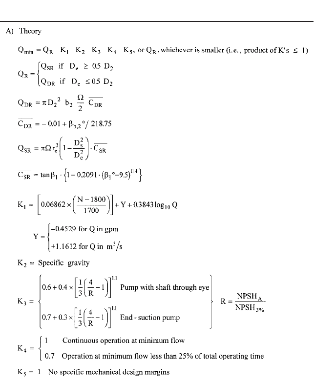
TABLE 16 General method for computing minimum flow: quantifying the energy-
level effect on Q
min
relative to Q
R
70
1800 rpm having explicitly appeared in the charts. NPSH plays a role in the determina-
tion of Q
min
—
through the factor K
3
—
because of the exacerbation of the unsteadiness and
pressure pulsations due to dilation of the cavities in the two-phase internal flows that
exist for any value of NPSH that is less than the inception NPSH
i.
(See the ensuing cavi-
tation discussion and the description in Section 2.3.1 that accompanies the definition of
NPSH-limits.)
As an example, the minimum flow of the high-energy pump suction stage of Table 14
and Figure 33 is computed in Part B of Table 16. (The value of R for the calculation of K
3
is taken from Table 18.) This machine has the relatively high energy level of some of the
boiler feed pumps shown in Figure 32 and listed in Table 13. Thus it is not surprising that
the resulting value of Q
min
is 90% of Q
R
(which equals Q
SR
, as is typical) and 48.5% of the
BEP flow rate. This is indicated on Figure 37, in which the computed performance curves
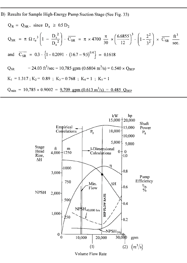
2.1 CENTRIFUGAL PUMP THEORY 2.83
FIGURE 37 Estimated performance of high-energy pump suction stage
TABLE 16 Continued.
of this pump are displayed. (See Part B of Table 14 for the main elements of these perfor-
mance predictions.) However, some of the remedies that have been discussed in this sec-
tion to counter the adverse effects of high-energy pump phenomena can reduce Q
min
to
lower values than this. In fact, the method contains the flexibility to take into account such
improvements through the factor K
5
.
2.84 CHAPTER 2
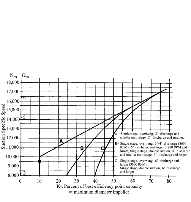
FIGURE 38 Minimum continuous stable flow (MCSF) for process pumps
71
In computing Q
SR
, the angle b
1
is called for. This is approximated by the inlet flow coeffi-
cient f
e
0.3 from Table 14, which corresponds to a nominal inlet tip flow angle of 16.7 deg.
The actual flow angle (and blade angle) at that location is slightly larger due to the hub-to-
shroud variation of the incoming meridional velocity as assumed in the development of the
inlet velocity diagrams of Figure 33. This will have a small effect on the results, depending
on how one interprets “b
1
”. In this regard, as can also be appreciated from the choices that
must be made for the Ks, the method of Table 16 is not precise; however, it is a useful indi-
cator of what the user and designer can expect in determining the operating range of a pump.
The above general theory for computing minimum flow is inclusive of all types of cen-
trifugal pumps and has found application especially for high-energy pumps, which can be
difficult to evaluate precisely in the varying circumstances of installation and operation in
which they are usually applied. The judgments that must be made in order to apply the
method of Table 16 can be largely avoided if actual data for Q
min
are available. It would in
fact be a monumental task to establish precise limits for all pump types and operational
envelopes. Nevertheless, the effect of energy level on MCSF has been found experimen-
tally for several classes of API process pumps through extensive testing. From this, Heald
and Palgrave have developed a method for computing the minimum flow of these pumps
as follows
71
:
(68)
where
(69)
and
(70)
Obtained from Figure 38, the factor K
7
accounts for the effects of speed and configu-
ration. As used in that chart
—
and in Eq. 69, the term suction-specific speed N
ss
(or
ss
)
K
M
K
M
31NPSH
A
>NPSH
R
2
BEP
, fluid4
K
7
K
7
1rpm, configuration, N
SS
2
Q
min
MSCF
K
7
100
K
M
Q
BEP
2.1 CENTRIFUGAL PUMP THEORY 2.85
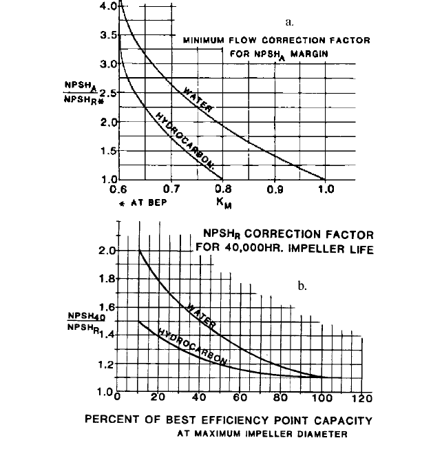
FIGURE 39 NPSH-effects on: a) MCSF and b) impeller life
71
does not mean that NPSH-effects are also included; rather, this expresses the fact that
the impeller design is affected by the designer’s choice of N
ss
as can be seen in the case
of the earlier Design Example, beginning in Table 6. This leads immediately in Table 7
to the inlet flow coefficient f
e
(through the NPSH-correlations of Table 1) and the
impeller eye diameter D
e
or radius r
e
. Following on from the discussion of Recirculation,
the ratio Q
SR
/Q
BEP
can be expected to increase with eye size or D
e
/D
2
. Being strictly based
on experiments, the Heald and Palgrave method does not deal explicitly with Q
SR
or Q
DR
,
but one can see from Eq. 38 that this principle is operative: Higher-N
ss
pumps require
greater MCSF. Before this fact was clearly understood, the trend was to design for
greater N
ss
—
in order to increase suction capability of these pumps. When operators ran
them back to the same low flows as they had done with earlier pumps designed for lower-
N
ss
capability, failures became epidemic. This led to a call for “lower-suction specific speed
pumps,” or, more accurately, pumps designed for lower-N
ss
capability; specifically 11,000
(
ss
4) or less
72
.
The NPSH-effect does come into play
—
as with K
3
in the previous general method
—
through the factor K
M
in Figure 39a. In this case, the term NPSH
R
means NPSH
3%
. Here
again, it is the ratio R NPSH
A
/NPSH
R
that is the determining factor because it is a mea-
sure of the cavitation activity that is invariably present in the first stage of a pump, and
2.86 CHAPTER 2
therefore in all single-stage pumps.The lower the value of R, the more violent the pressure
pulsations accompanying the recirculating fluid and the consequent vibration. The situa-
tion is mitigated considerably at greater R, and K
M
operates through Eq. 68 to decrease the
MCSF. Of course, if R were great enough
—
often 5 or more
—
NPSH
A
would exceed NPSH
i
(as discussed in Section 2.3.1) and there would then finally really be no cavitation in the
pump. (That high a value of NPSHA is rare; for, if it were supplied, there would hardly be
a need for a pump in the first place.)
Figure 39a also brings in the effect of the liquid being pumped.When room temperature
water boils (cavitates), the mass boiled off by the local drop below the vapor pressure makes
considerably more cavity or bubble volume than some other liquids, namely hydrocarbons
and hot water
17
. (See Section 2.3.1.) The table refers to room temperature or cold water.
By way of illustration, computing the minimum flow of the end-suction volute pump of
the Design Example begins with Curve B in Figure 38 (for pumps with 6-inch discharge
and larger and for 1800 rpm and lower as stated on the figure). [This pump has a dis-
charge port of about 9 inches (229 mm) as would be the case if the velocity in this port were
half of the throat velocity V
T
in Part A of Table 11, as suggested previously in the para-
graphs on Volutes under Designing the Collector.] N
ss
for this pump was chosen as 12,300
(
ss
4.5), which yields 41.5% for K
7
. If it were decided to provide this cold-water pump
with 16.4 ft (5 m) of NPSH
A
, R would be 1.17, and the figure yields 0.97 for K
M
. [NPSH
3%
14 ft. (4.27 m) for this pump, as seen in Table 6.] Thus, from Eq. 68, this pump has an
MCSF of 0.415 0.97 or 40% of Q
BEP
. Had it been designed for N
ss
11,000 (
ss
4.025),
and if R still were 1.17, the NPSH
A
would have been 19 ft (5.8 m) and MCFS would have
been 0.36 0.97 or 35% of Q
BEP
. Moreover, if it were pumping hydrocarbons at this same
NPSH
A
, MCFS would have been even lower, namely 0.36 0.78 or 28% of Q
BEP
. It would
appear, though, that for many applications, the pump as designed (at
ss
4.5) has a low
enough energy level to allow for an adequate range of flow-rate capability, and that there-
fore, the value N
ss
12,300 is in this case not excessive.
Cavitation Considerations Having alluded to and treated the subject of cavitation a
number of times in this section, we should expand on the role that this ever-present phe-
nomenon plays in the operation and durability of centrifugal pumps, particularly those
having a high energy level. The manifestations of cavitation that are encountered and
become issues for the operability and life of a pump are a) cavitation accompanying back-
flow from the impeller eye, b) cavitation-generated instabilities and pressure pulsations,
and c) erosion, which involves the prediction of the NPSH
R
-versus-flow rate characteris-
tic curve to maintain life and, conversely (d) the prediction of life for a given NPSH
A
. The
range of NPSH over which cavitation occurs within a pump extends from the point where
pump head or pressure rise undergoes an identifiable drop
—
usually 3% for repeatable
results for the NPSH-value involved
—
namely the “performance-NPSH” or NPSH
3%
—
upwards. As NPSH increases from this point, there is an extensive range over which no
observable performance loss is detected, yet erosive damage is progressing at a sometimes
excessive rate. Finally, at the upper end of the range, all two-phase activity ceases
—
all
bubbles and cavities are suppressed
—
namely, at the inception-NPSH value or NPSH
i
.As
stated previously, NPSH
i
has been observed to be typically about five times NPSH
3%
. This
is clearly described in Section 2.3.1, in which the different NPSH-limits are distinguished.
The following cavitation considerations pertain to this range.
a) Cavitation and backflow. The minimum flow limits imposed by the R-value or NPSH-
effect arise partly because a lower flow rate at a low NPSH
—
although it may be in excess
of NPSH
3%
—
involves a strong interaction between suction recirculation and cavitation
that can be intense, especially for inducers and large-eye (large D
e
/D
2
) impellers. At flow
rates Q V Q
SR
, there exists upstream of the impeller an annulus of back-flowing fluid that
emerges from the impeller. Drawing the velocity diagram at the impeller leading edge at
the shroud for the case of reversed flow reveals that the absolute velocity component V
i) is mostly circumferential and ii) is greater than the impeller tip speed U
t,1
or U
e
. Thus
the fluid leaving the impeller hugs the outer wall of the approach passage. If this passage
is an axial pipe supplying an end-suction impeller or inducer, the pressure along the cen-
terline can be below the vapor pressure, thus creating a vapor core that extends many
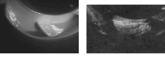
2.1 CENTRIFUGAL PUMP THEORY 2.87
FIGURE 40 Cavities on impeller blades at BEP flow rate: a) NPSH = 2 NPSH
3%
; b) NPSH = NPSH
3%
. (Source:
Flowserve Corporation)
61
a. b.
diameters upstream, as was shown in a photograph that is part of an article by Yedidiah
73
.
Obviously the energetic backflow has to be balanced by an equivalent inflow that enters
the impeller from the interior of the pipe and therefore along the hub streamline of the
impeller. Vapor from the core is drawn in also and tends to fill the impeller and vapor-lock
it. At this point, the pressure to drive the highly spinning liquid upstream is non-existent
and the backflow ceases. The vapor core disappears and the impeller once more begins
ingesting liquid, the process just described repeating itself at a very low frequency (as low
as 1 to 6 Hz) and called cavitation surge
74
. It has been found possible to passively divert
the backflowing liquid outward from the inlet passage at the impeller or inducer eye into
a series of vaned passages surrounding the inlet pipe, the vanes deswirling the back-
flowing liquid and returning it to a point or annular port upstream. Properly designed,
this “backflow recirculator” has completely eliminated all cavitation instabilities in induc-
ers
—
over the full range of flow rate from shut-off to run-out. It was shown to work for
some high-N
ss
impellers to which it was applied
74
. Cavitation surge, however, is rarely seen
in low-N
ss
impellers and is usually completely avoided by running the pump at flow rates
greater than minimum flow Q
min
as established by one of the previous methods or by test.
b) Cavitation-related instabilities and pressure pulsations. At flow rates greater than
Q
min
, cavitation can cause or intensify pressure pulsations. Such instabilities are connected
with the variety of cavity and bubble configurations that can exist over the range of flow
rates and NPSH- or R-values. The nature and extent of cavitating flow within a pump
has been studied extensively by visual observation. Figures 40 and 41 are laboratory pho-
tographs
61
of a sector of a boiler feed pump impeller eye, in which the suction sides of some
of the blades are visible. These were taken with the aid of a bright flash that lasted for 1
ms. They can also be found in Ref. 24 of Section 2.3.1. Figure 40a shows the sheet cavity
that exists at BEP flow rate and at an R-value of 2. Also observed at BEP
—
but at R 1
(that is, NPSH NPSH
3%
)
—
is the thick, extensive cavity of Figure 40b. This cavity
extends from the blade leading edge to the throat formed by the leading edge of the fol-
lowing blade, and this same pattern exists on every blade. Most observers note that when
this suction-side cavity reaches the next throat, the pressure rise or liquid head starts
breaking down
—
which is what is recorded at this “3-percent-NPSH” point. Instabilities
tend to be at a minimum at both of these relatively steady-flow conditions.
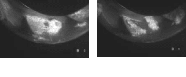
Figure 41, on the other hand, displays highly unsteady cavity flows. Both photographs
(A and B) were taken at the same half-flow condition at different instants
—
for R 2. A
similar sequence of three photographs at this condition appears in Section 9.5, and none
of the three possesses a cavity pattern that resembles either of the others. The position of
the somewhat smaller cloud in Figure 41b that has broken off the main cavity appears to
be traveling toward the pressure-side (out of sight) of the next blade. Pressure-side cavi-
tation erosion would be the result, and this accords with the findings in Section 2.3.2.
Pressure pulsations are associated with unsteady cavitation patterns, and plots of the
amplitude and frequency of suction pressure pulsations show increasing frequency as R is
2.88 CHAPTER 2
FIGURE 41A and B Cavities on impeller blades at half the BEP flow rate: NPSH = 2 NPSH
3%
. (Source:
Flowserve Corporation)
61
a. b.
increased
—
as would be expected as bubble size is reduced. The amplitude peaks at R
greater than 1
—
usually closer to 2. Elimination of these instabilities is best done by avoid-
ing cavitation. This can be done by increasing NPSHA and optimizing the blade shape for
minimum cavity activity
75
. To avoid the excessive pump and system oscillations that can
occur, some users specify that a cavitation-flow visualization test be conducted and require
that minimal or no cavities shall be observed.
c) Erosion due to cavitation and the prediction of the Life-NPSH. In the majority of cases
cavitation is unavoidable, and the issue becomes the life of component (usually the
impeller) in resistance to attack by collapsing bubbles and larger cavities as they are
swept out of the low-pressure regions near the blade leading edges. The pressure created
at the point and instant of collapse is immense. Photographs of the erosive damage result-
ing from this activity can be found in Sections 2.3.1 and 9.5. The surface failure mecha-
nism is one of fatigue due to repeated collapse of bubbles adjacent to the blade. This
happens at a large number of closely spaced sites, the resulting erosion having a strongly
pitted texture. The rate of erosive depth penetration into the surface of a venturi subject
to bubble collapse was found by Knapp
76
to increase as the sixth power of velocity V at a
constant cavitation number k 2(p
1
p
v
)/rV
2
. In other words, the erosion rate increased
as the third power of (p
1
p
v
) or NPSH at the inlet of the venturi, which means that the
collapse pressure rises with NPSH, as is known from the Rayleigh bubble collapse the-
ory. The velocity V in Knapp’s venturi corresponds in a pump to the maximum relative
velocity W at inlet
—
which is conveniently represented by the impeller inlet tip speed U
t,1
as a criterion for damage rate
—
and t corresponds to the cavitation number k. For a given
impeller at constant Q/N and a constant value of t, (or at a constant available suction
specific speed,) the higher U
t,1
is, the greater the NPSH and the greater the damage rate.
Also, as mentioned earlier, a higher value of U
t,1
implies a correspondingly greater U
2
and,
therefore, greater pump pressure rise or head. Therefore, high-head pumps are more likely
to suffer from cavitation erosion, making cavitation a “high-energy” pump phenomenon.
High pressure-rise has already been shown to be a feature of high energy pumps through
the definition of energy level in terms of classical stress loading (Figure 32).
Facing the reality of high-energy pump destruction due to cavitation erosion, Vlam-
ing redefined the term “NPSHR” to mean NPSH
40,000 hrs.
; that is, the NPSH needed to
limit the damage sufficiently so as to ensure an impeller life of 40,000 hours. He devel-
oped an empirical method for predicting the curve of this “damage-NPSH” versus flow
rate for conventionally-designed impellers
77
. This method is defined in Table 17 and
includes the inlet tip speed effect on the erosion rate. A value of the vaporization factor
C
b
that is less than unity applies to hot water and to other liquids such as hydrocar-
bons, which generate far less vapor volume when they cavitate than does cold water.
(See the earlier discussion under NPSH Effects in the subsection on Specific Speed and
Optimum Geometry.) (Rather than depend on theory for the API process pumps men-

2.1 CENTRIFUGAL PUMP THEORY 2.89
TABLE 17 NPSH required for 40,000 hours life
77
tioned earlier in connection with their minimum flow data, Heald and Palgrave quan-
tified NPSH
40,000 hrs.
in Figure 39b
71
.)
Applied to the high-energy multistage pump suction stage of Figure 33 and Table 14,
Vlaming’s method yields the NPSH
R
-values shown in Table 18 under the heading f
e
0.3.
These are plotted as the NPSH
40,000 hrs.
-curve on Figure 37. The blades of the pump are
assumed to be set for zero incidence of the incoming flow to their camber lines at the BEP
—
called “shockless entry” and denoted by “SE.” (Many designers make Q
SE
somewhat
larger than Q
BEP
to achieve lower NPSHR at Q Q
BEP
.) The column to the right in the
table contains the results for the same method applied to the more common case for high-
energy pump suction stages, namely f
e
0.25 (and lower). For the same shaft diameter,
flow rate and speed, f
e
0.25 yields a larger eye diameter through Eq. 49; namely, 13.92
in. (353.6 mm) versus 13.37 in (339.6 mm) for the f
e
0.3 case as shown in Figure 33.
Moreover, that figure shows the inlet tip speed U
t,1
(U
e
) to be 274 ft/sec (84 m/s), whereas
for the larger-eye case the value is computed to be 286 ft/sec (87 m/s). As Table 18 reveals,
this larger-eye impeller has a lower value of NPSH
3%
(as computed from the correlations
of Table 1), which is the reason for sizing large eyes. But Vlaming’s method indicates that
the smaller eye requires less “damage-NPSH” (R 1.69) than does the larger eye (R
2.06), even though the latter requires less “performance-NPSH” or NPSH
3%
. So, from both
a minimum-flow and a cavitation damage standpoint, the advantage of a smaller eye for
high energy levels is evident.
d) Prediction of life for a given NPSH
A
. The inverse of the foregoing problem is how to
determine the life under cavitating conditions at a given value of available NPSH.Gülich
found a connection between an observed length L
cav
of the cavity trailing off the leading
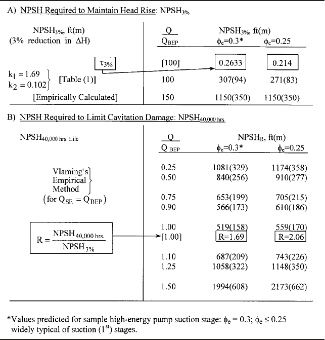
2.90 CHAPTER 2
TABLE 18 NPSHR of high-energy pump suctions stages
edge of the blade at BEP (Figure 40a) and the life of an impeller operating at this condi-
tion
78
. The resulting procedure is outlined in Table 19, beginning with the definition that
the life is the time it takes for the erosion to penetrate through 75% of the blade (or wall)
thickness. In the absence of a cavitation-visualizing test, L
cav
can be estimated as sug-
gested by the last two formulas in Table 19
75
. Critical to this estimate is the assumed value
of the “inception-NPSH” or t
i
. For conventionally designed impeller blades, t
i
1 at the
BEP, whereas aerodynamically shaped blades that minimize the local reduction of static
pressure have been produced with t
i
0.5 at the BEP
75,79
. The life computations of Table
20 follow from application of the method of Table 19 to the sample suction stage of Fig-
ure 33 for t
i
1 and 0.5. Higher values of t
i
apply for Q Q
BEP
—
as might be expected
from the shape of Vlaming’s NPSH
40,000 hrs.
-curve in Figure 37 and the fact that the local
pressure reduction in the leading-edge region increases with incidence. From this and the
results of Table 20, it is evident that improvements to conventional blade-design practice
are essential if life is to exceed half a year. Further, this life calculation method is based
on the existence of a sheet cavity like that of Figure 40a; and the disordered cavity struc-
tures of Figure 41, which happen in the presence of recirculation, are not addressed. Low-
flow cavitation damage is generally more severe, and is described in Section 2.3.2.
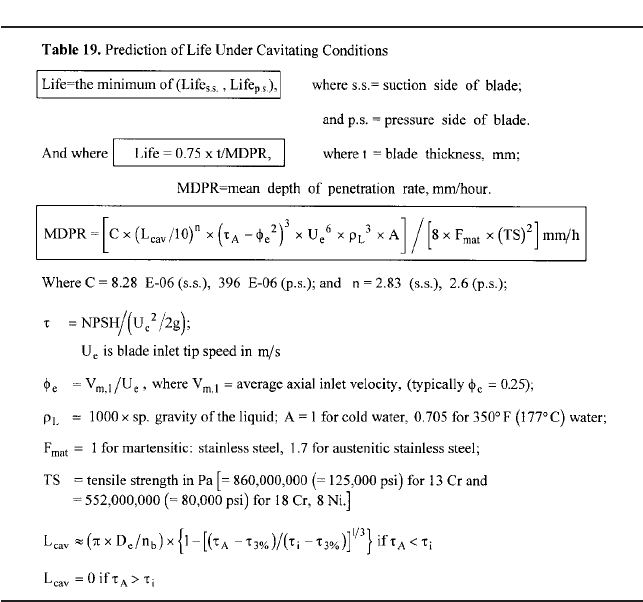
2.1 CENTRIFUGAL PUMP THEORY 2.91
TABLE 19 Prediction of life under cavitating conditions
(mm)
dimension less
Moreover, corrosion can play a role in cavitation-related erosive activity, an effect that was
also addressed in Gülich’s work.
78
Nevertheless, the ability to compute erosive behavior
—
even at the BEP
—
allows one to evaluate design improvements and provides a good idea
of the life that can be expected under normal operating conditions.
Obviously, if the available NPSH is greater than the inception-NPSH (that is, t
A
t
i
),
there is no bubble activity of any kind, and at Q
BEP
the cavity length L
cav
0.An illustration
of what can be achieved in this regard is presented in Figures 24 and 25 of Section 9.5, which
are the “before” and “after” photographs of the model impeller blades for the first stage of a
24,000 hp (18 MW) pipeline pump. Quasi-three dimensional analysis of the blade pressure
loading led to changes in shape that eliminated the cavities
53,75
.This complete absence of cav-
itation is becoming the desired objective for the design and application of new and upgraded
multistage high-energy pump suction stages. This approach eliminates both the erratic
mechanical behavior that occurs in response to unsteady cavity patterns and the erosion due
to bubble collapse; thereby substantially increasing the life and reliability of such machines
80
.