Pump Handbook by Igor J. Karassik, Joseph P. Messina, Paul Cooper, Charles C. Heald - 3rd edition
Подождите немного. Документ загружается.

2.22 CHAPTER 2
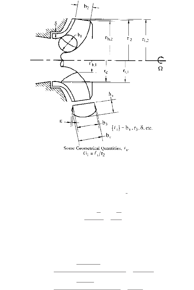
FIGURE 8 Defining the geometry of a pump stage
size of the pump stage a priori; so, r
2
is eliminated by replacing Q
s
in Eq. 35 with a new quan-
tity that is the result of dividing the square root of Q
s
by the -power of the head coefficient c.
Thus, from the definitions just given of Q
s
and c, one arrives at the specific speed
s
as the
independent variable in terms of which the geometry is optimized
3
:
(37)
For convenience, specific speed is usually expressed in terms of the conventional quan-
tities N, Q, and H that correspond to the factors in Eq. 37, which quantities are expressed
in the units commonly used commercially. For example, forms found in the United States
and in Europe and the relationship of these to the truly unitless “universal specific speed”
s
defined in Eq. 37 are as follows:
(38a)
(38b)
Thus,
(38c) n
q
1m
3
>s, m2 N
s
1USgpm, ft2>51.64
s
N1rpm22Q1m
3
>s2>3¢H1m24
3>4
52.919
n
q
52.919
s
N1rpm22Q1USgpm2
>3¢H1ft24
3>4
2733.016
N
s, 1U.S.2
2733.016
s
2Q
1g¢H2
3>4
2Q
s
c
3>4
3
4
2.1 CENTRIFUGAL PUMP THEORY 2.23
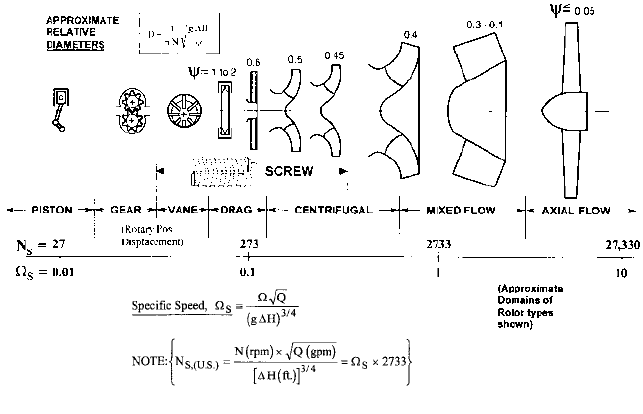
FIGURE 9 Optimum geometry as a function of BEP specific speed (for single-stage rotors)
Rotor Shape as a Function of Specific Speed Optimization of pump hydraulic geom-
etry in terms of the BEP specific speed has taken place empirically and analytically
throughout the history of pump development. An approximate illustration of the results
of this process for pump rotors or impellers is shown in Figure 9. Not only does the geom-
etry emerge from the optimization process but also the head, flow, and power coefficients
for each shape as well. Approximate values for the optimum BEP head coefficient c are
shown on the figure. The actual rotor diameter can then be deduced as noted
—
from the
c-definition of Eq. 31. The relationship among the various rotors is illustrated in the fig-
ure
—
assuming that they all have the same speed and head; that is, as one moves along
the abscissa or specific speed axis of Figure 9, only the flow rate is changing as far as the
illustrations of the rotors are concerned. As would be expected, therefore, high-specific-
speed impellers need to have large passages relative to their overall diameter. This is pow-
erfully illustrated if one contrasts the propeller (high-
s
) with the low-
s
centrifugal
impeller.
At the lower end of the specific speed range shown in Figure 9, rotodynamic pumps
(that is, centrifugal pumps, in which category mixed- and axial-flow geometries are gen-
erally included) would be too low in efficiency to be practical. Rather, rotary positive dis-
placement pumps take over because there is a transition through the drag pump domain.
Sometimes called a regenerative or periphery pump, the drag pump is actually a rotody-
namic machine, developing head peripherally around the impeller through successive
passes radially through the blades on both sides until a barrier is reached at some point
on the periphery, where the fluid is then discharged.
5
The screw pump, on the other hand, is a truly positive displacement (rotary) machine.
It can have two, three, or more meshing screws and can move large quantities of fluid
—
both single- and multiphase
—
against a large pressure difference p, giving it a specific
speed range that extends well into centrifugal pump territory. Not shown is the pro-
gressive cavity pump, which has a single screw surrounded by an elastomer sealing
member.
Lower flow rates are readily accommodated by the vane pump, whereas gear pumps
handle a higher range of pressure differences at such flow rates. Finally, extremely high
pressures are produced by reciprocating pumps, the specific speed range of which extends
off the figure on the left.
2.24 CHAPTER 2
Positive displacement pumps appear in Figure 9 in order to provide perspective. The
concept of specific speed is not generally applied to these machines, because a given posi-
tive displacement pump can have such a wide range of pressure-rise capability at a cho-
sen flow rate and speed as to make it difficult to associate a given rotor geometry with a
particular value of specific speed. On the other hand, a unique rotodynamic pump geome-
try is readily associated with the specific speed of the BEP of such a machine.
Performance of Optimum Geometries Figure 9 enables one to easily identify the pump
stage types associated with required pumping tasks in terms of head, flow rate, and rota-
tive speed. Beyond this general picture is the related performance of a real pump geometry
in a real fluid. Although, for centrifugal pumps, the specific speed has the major effect on
performance, the available NPSH and the viscosity of the pumpage also have an influence.
These are evident in the following formal statement of the efficiency of an optimized pump
(cf Eq. 35)
(39)
where the radius r
2
, representing the size, has been eliminated from the other variables in
Eq. 35 by introducing the suction specific speed
ss
and the head-flow Reynolds number
R
e,H,Q
, which are defined in Eqs. 40 and 41:
(40)
(41)
where, the common form of the suction specific speed, called N
ss
, is given in commercial
U.S. units by (Eq. 42)
(42)
Size Effect For sufficiently high NPSH (or sufficiently low suction specific speed) and
low viscosity (or high Reynolds number), real pumps also possess a strong size effect on
efficiency. This is because, in normal manufacturing processes, the clearances d prevent-
ing internal leakage Q
L
(for example, past the impeller sealing rings in Figure 2) do not
scale up as rapidly as the size (represented by r
2
), nor do the surface roughness heights
e. Thus, a larger pump tends to be more efficient. Strictly speaking, however, the geome-
try of the larger pump is not the same as that of the smaller pump, and this forces one to
modify Eq. 39 by reintroducing two of the length ratios G
i
that were part of the set {G
i
}
in Eq. 35 which characterize the hydraulic shape of the machine. Thus, Eq. 39, revised to
reflect these realities, becomes
(43)
A study of a large number of commercial centrifugal pumps by H. H. Anderson
6
has
quantified Eq. 43 for such machines. These pumps were all operating in water and had
sufficient NPSH for performance not to be influenced by
ss
. The results are given by Eq.
44, which is plotted in Figure 10:
(44) h 0.94 0.08955 c
Q1gpm2
N1rpm2
X d
0.21333
0.29 clog
10
a
2286
N
s
bd
2
1h
max
2
5G
i
6
opt.
f
1
a
s
,
ss
, R
e, H, Q
, 52-£6, 5
p
6, 5g6,
e
r
2
,
d
r
2
b
N
ss, 1U.S.2
N1rpm22Q1gpm2
3NPSH 1ft24
3>4
ss
2733.016
ss
2Q
1g NPSH2
3>4
2Q
s
1t
2
>22
3>4
R
e, H, Q
2Q
1g¢H2
1>4
n
R
e
2Q
s
c
1>4
1h
max
2
5G
I
6
opt
f 1
s
,
ss
, 52-£6, 5
p
6, 5g6, R
e, H, Q
2
2.1 CENTRIFUGAL PUMP THEORY 2.25
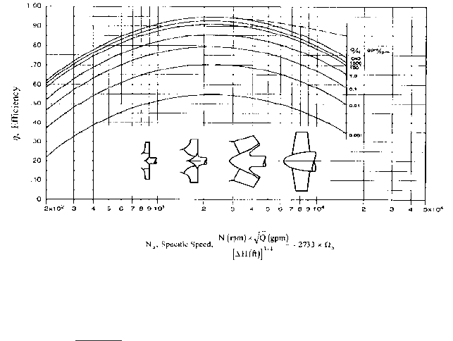
FIGURE 10 Efficiency of centrifugal pumps versus specific speed, size, and shape–adapted from Anderson
6
.
Note: Actual experience for Ns 2286 shows higher efficiency, as indicated by the dashed line.
where
Eq. 44 is a combination of separate relationships described by Anderson for efficiency and
speed as functions of flow rate
6
. Included is a correction for specific speed that is too con-
servative for N
s, (U.S.)
2286 or
s
greater than about unity. With this qualification, Figure
10 is a useful representation for centrifugal pumps and is often as far as many users go in
determining the performance of these machines.
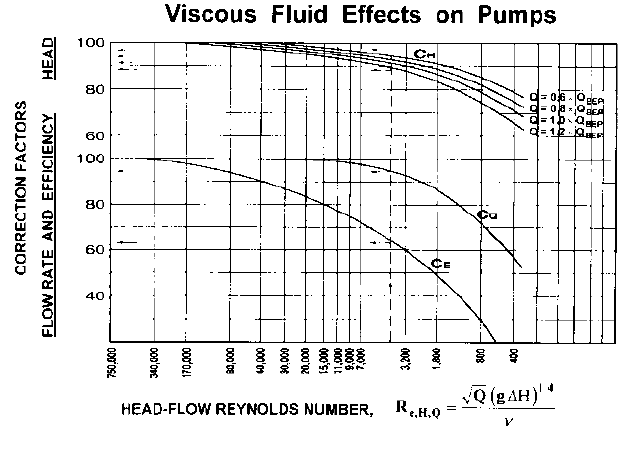
Viscosity Effects Centrifugal pump geometries have not generally been optimized ver-
sus Reynolds number
—
often because the effect on hydraulic shape is not very great except
for the highest viscosities of the pumpage, and a given application can sometimes expe-
rience a substantial range of viscosity. Studies of conventional centrifugal pumps over a
range of Reynolds number have been combined in nomographic charts in the Hydraulic
Institute Standards, which yield correction factors to the head, efficiency, and flow rate of
the BEP of a low-viscosity pump in order to obtain the BEP of that pump when operat-
ing at higher viscosity
7
. Figure 11 is a presentation of these correction factors in terms of
the head-flow Reynolds number. Strictly speaking, in view of Eq. 43, each pump geome-
try has a unique set of such correction factors, yet the data presented in Figure 11 have
been widely utilized as reasonably representative of conventional centrifugal pumps.
NPSH Effects In many cases, the available NPSH is low enough, or the suction-specific
speed
ss
at which the pump stage must operate is high enough for significant two-phase
activity to exist within the impeller. This is to be expected in centrifugal impellers of water
pumps if the available
ss
is greater than about 3 to 4 (or N
ss,(U.S.)
8,000 to 11,000). In
such a case,
ss
and the vaporization quantities {2-} in Eq. 35 dictate a profound change
in the impeller geometry into that of an inducer. The inducer has an entering or “eye”
diameter that is significantly enlarged
—
together with tightly wrapped helical blading.
Often the inducer is a separate stage that pressurizes the two-phase fluid as needed to
provide a sufficiently low value of
ss
at the entrance of the more typical impeller blad-
ing that is immediately downstream of the inducer. If the two-phase fluid is near its ther-
modynamic critical point, the {2-} operate to greatly reduce the amount of two-phase
X c
140
1min.2
d
2
2.26 CHAPTER 2
FIGURE 11 Viscous fluid effects on centrifugal pumps—adapted from Hydraulic Institute ANSI/HI 2000 Edition
Pump Standards, Reference 7.
activity within the pump. (At the critical point, the liquid and gas phases are identical,
and therefore both have the same specific volume.) An example is the pumping of liquid
hydrogen, for which an inducer is unnecessary until much higher values of
ss
are
reached. Moreover, inducers
—
typically limited to
ss
-values of about 10 (N
ss,(U.S.)
27,000)
in water
—
can, at sufficiently low tip speed, operate at zero NPSH, which corresponds to
an infinite value of
ss
8
.
Pumping Entrained Gas In addition to the liquid’s own vapor (which is the gas involved
in the NPSH-effects discussion), many pumping applications deal with a different gas; that
is, a different substance from the liquid being pumped. The effects of this gas on perfor-
mance arise from a) the volume flow rate of the gas at the inlet, b) the pressure ratio of
the pump, which determines how far into the impeller this gas volume persists; that is,
how much it gets compressed, and c) how much of the gas dissolves in the liquid as the
pressure increases within the pump, which depends on both the solubility and the degree
of agitation of the fluid produced by the pump. The set of fluid properties associated with
these gas-handling phenomena are represented by {g
p
} in Eq. 34, the dimensionless form
(Eqs. 35 and 43) of this set being {
p
}. Generally, for typical commercial centrifugal pumps,
the performance under such conditions usually manifests itself as a loss of pressure rise,
which is reasonably stable up to an inlet volume flow rate fraction of gas to liquid of 0.04
to 0.07
9
. Inducers can handle larger inlet volume fractions of gas, and, under Dalton’s law
for partial pressures, the liquid’s own vapor also occupies the volume of the gas bubbles.
Single and multistage centrifugal pumps have been built that handle far greater gas vol-
ume than these single-stage values
10,11
; moreover, multiphase rotary positive displacement
screw pumps can handle gas volume fractions up to 1 (100 percent gas)
11
.
Effects of Slurries and Emulsions Finally there is the influence of the dimensionless
quantities {g} in Eq. 43. Impeller and casing design are altered so as to reduce wear-
producing velocities if the pumpage is a slurry of solids contained in a carrier liquid.
(Slurry pumps are usually single-stage machines with a collector or volute casing sur-

2.1 CENTRIFUGAL PUMP THEORY 2.27
rounding the impeller.) This usually means a smaller impeller eye diameter (which, as can
be seen in Figure 6, reduces the inlet relative velocity W
1
,) and a larger radial distance
from the impeller to the surrounding volute because the circumferential velocity compo-
nent V
u
of the fluid emerging from the impeller (also seen in Figure 6) slows down with
increasing radial position and is then lower in the volute passageway
12
. Performance also
is altered, depending on the composition and concentration of the slurry. These are com-
plicated non-Newtonian flows and are covered in detail elsewhere in this book in con-
junction with a thorough treatment on solids-handling pumps. Emulsions are another
example of such flows, many of which are destroyed by excessive local shear in the fluid.
For this reason, screw pumps are sometimes utilized for emulsions rather than oversized,
slow-running centrifugal pumps. Except for thin layers of the fluid at the clearances, most
of the flow in a screw pump experiences very little shear in comparison to the flow through
a centrifugal pump.
Electromagnetic Effects Not appearing in Eq. 43 are quantities associated with elec-
tromagnetic phenomena. For example, electric current flowing radially outward through
fluid contained in an axially directed magnetic field is capable of producing a rotating flow.
Called a hydromagnetic pump, this device is therefore “centrifugal,” yet it has no moving
parts. Such pumps have been used for liquid metals and could be made reasonably effi-
cient for any pumpage with high conductivity.
DESIGN PROCEDURES _______________________________________________
Establishing the Pump Configuration
The first step in designing a pump is to deter-
mine the type and number of stages that are needed to meet the given set of operating
conditions, usually Q, p
1
, p
2
, available NPSH ( NPSHA) and specific gravity of the fluid.
If the pump must meet several such sets of operating conditions, one set has to be chosen
for the BEP or design point so all the others are satisfied, if possible. Making the proper
choice of this BEP may require some iteration: first making a trial choice, doing a pre-
liminary design, and determining the corresponding pump performance characteristic
curves, and then repeating these steps if necessary.
Pump rotative speed N (rpm) must be chosen in order to proceed. Selection of the high-
est practical rpm is desirable because it yields the smallest size and therefore usually the
lowest cost and easiest containment of system pressure. If, for the chosen number of
stages, the stage specific speed is too low, Figure 10 indicates that efficiency is generally
improved with greater speed. The maximum possible rpm is that which yields a value for
the suction specific speed
ss
(Eq. 41) or N
ss
(Eq. 42) that the first stage of the pump can
accommodate, where NPSH is found from Eq. 41 as follows:
(45)
Typically, the
ss
-capability of an impeller does not exceed a value that is somewhere
in the range 3 to 4.5 (N
ss
8,200 to 12,300), depending on minimum (off-design) flow rate
requirements, and it is typically 10 (27,000) or less for inducers. Generally, the supplier
furnishes a pump that has a value of NPSH-capability (or “NPSHR”) smaller than the
stated NPSHA. This difference or “NPSH-margin” is desirable if there is any uncertainty
as to the true value of NPSHA. It is essential for high values of p
stg
; (see discussion of
“high-energy pumps” further on in this section.) Often a higher speed can be employed
if a double-suction impeller (entry of fluid from both sides) can be used, as then only half
of the given Q enters each side of this impeller, and only that half can be used in the
ss
-
equation applying to that fluid and impeller type.
The double-suction configuration is popular for large, single-stage pumps because the
axial thrust is nominally zero. It is also found as the first stage in some multistage pumps,
in which case the arrangement of the remaining impellers can be “back-to-back” (half of
them facing in one direction and half opposite) to achieve axial thrust balance. On the
NPSH
1
g
a
ss
b
4>3
Q
2>3
2.28 CHAPTER 2
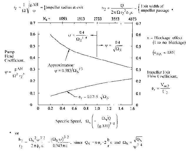
FIGURE 12 Sizing factors for the diameter and width of typical impellers—adapted from Stepanoff
4
.
other hand, the interstage flow passages are simpler if these impellers are all facing in the
same direction
—
in which case the thrust is opposed by a balancing drum or disk as
described in Section 2.2.1. Forming the specific speed from N, Q,and H (from Eq. 3) and
referring to Figure 9 for the kind of impeller (which then gives one an idea of the other
hydraulic components (inlet passage, diffuser and collector, and so on) and Figure 10 for
the expected efficiency, one can decide whether the pump would perform better and still
meet any installation and size restrictions with more than the one stage implied by this
first N
s
-calculation.
If the user requires the performance characteristics of a positive displacement pump
—
such as a wide range of pressure-rise at a nearly constant flow rate Q
—
selecting such a
pump may be possible if the specific speed is not too high. (See Figure 9.) The choice of
speed for positive displacement pumps is sometimes determined by mechanical consider-
ations rather than suction capability.
Sizing the Pump The next step is to determine the approximate size of a pump or
pump installation. Beginning with the impeller, the agent of the energy transfer to the
fluid in a pump, one utilizes the results of the pump hydraulic geometry optimization
process. This also yields the proportions of the velocity diagrams that correspond to the
geometry associated with the desired value of specific speed. These in turn lead to two
major sizing factors for an impeller, which are plotted for typical commercial pumps in
Figure 12; namely the head coefficient c (originally defined in Eq. 31) and the outlet flow
coefficient f
i
defined on this figure
4
. Equations in the figure show how these factors are
used to determine the exit radius r
2
(or diameter D
2
) and the width b
2
(Figure 8) respec-
tively. The flow coefficient f
i
is obviously a velocity component ratio. For the head coeffi-
cient of a pump with zero inlet prewhirl to the impeller (that is, V
u,1
0), the relevant

2.1 CENTRIFUGAL PUMP THEORY 2.29
velocity ratio (see Figure 3) is V
u,2
/U
2
, which in view of Eqs. 15b and 31 is equal to the
ideal head coefficient c
i
, as this corresponds to the ideal head H
i
. Referring to Eq. 15c, it
is obvious that the actual head coefficient c h
HY
x c
i
, or, in the (common) case of zero
prewhirl, c
i
V
u,2
/U
2
.
Overall pump dimensions are conveniently viewed in terms of factors times the
impeller diameter. The overall diameter exceeds that of the impeller due to the surround-
ing casing. For single stage pumps, this casing will include a volute and perhaps a set of
diffuser vanes immediately surrounding the impeller; so, the casing diameter can be 50%
greater than D
2
or more. On multistage pumps (many with radial-outflow diffusers and
return vanes), this excess is often less than 50%.
Single-stage pump axial length includes provision for inlet passageways and bearing
housings and is therefore approximately the same as the overall pump diameter. On the
other hand, the axial length of a stage in a multistage pump is often less than half of the
impeller diameter. Minimizing this “stage length” (and diameter) is a goal of competitive
pump designers in the quest to create a machine of light weight and low cost. But too
small a stage length is accompanied by inferior hydraulic performance because not
enough room is provided for the passages around and within the impeller to turn the
fluid with minimum loss. Further, the bearing housings and the suction and discharge
“heads” or end pieces must be considered in arriving at the overall length of a multi-
stage pump.
This sizing discussion so far has focused on pumps with a radial-outflow geometry. For
the axial-flow geometries of higher specific speeds, the situation is simpler. The diameters
of the propeller (Figure 9) and any stationary vanes downstream (or upstream) are essen-
tially the same. The approach and discharge piping is of about the same size. A simple
guideline for the maximum radius of the propeller is found from the following approximate
extrapolation of the c-curve of Figure 12:
(46)
where the outer radius of the propeller r
t,2
should be substituted for the mean exit radius
r
2
in the c-definition. Thus the c-curve is in reality a c
t
-curve for non-radial-flow pumps.
For small departures from radial flow, as illustrated in Figure 8, the c-curve of Figure 12
can be used either way.
These guidelines are often all that pump users or fluid system designers need to plan
their installations. To get beyond this overview, one must pursue the hydraulic design in
detail
—
as afforded by the following development and examples.
Designing the Impeller Determination of the geometrical features of the impeller is
generally accomplished in the following order: a) the “eye” radius r
e
, b) the exit radius r
2
or r
t,2
, and c) the exit width b
2
or, in the case of mixed- and axial-flow impellers, the hub
exit radius r
h,2
—
all of which form the starting point for d) shaping the hub and shroud
profiles (Figure 13); and, finally, e) construction of the blades.
a) The eye. The inlet radius of the impeller eye r
e
(Figure 13) is nearly the same as r
t,1
,
which is the diameter of the tips of the impeller blades at the inlet. This emerges after
the eye flow coefficient f
e
V
e
/U
e
[the ratio of the one-dimensional axial velocity enter-
ing the eye (Figure 8) to the tangential speed of the impeller eye U
e
r
e
] is known:
(47)
(48)
Thus, r
e
can be found from the following combination of Eqs. 47 and 48:
A
e
p1r
e
2
r
s
2
2
f
e
Q>A
e
r
e
V
e
U
e
c
t
0.53
s
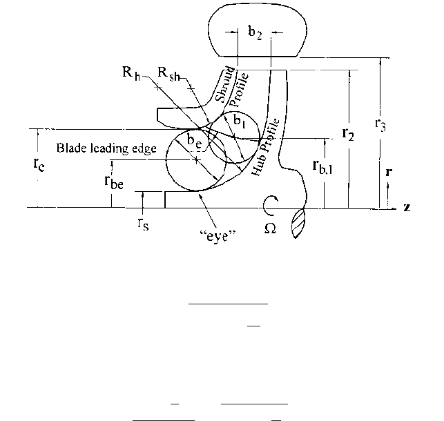
2.30 CHAPTER 2
FIGURE 13 Hub and shroud profiles of centrifugal pump impeller
(49)
where the shaft-to-eye ratio r
s
/r
e
can be estimated at first. Typical values for f
e
vary from
0.2 to 0.3 for impellers and down to 0.1 or less for inducers, depending on suction condi-
tions, as can be seen from its relationship to suction-specific speed:
(50)
where the cavitation coefficient t (cf. t
2
in Eq. 36) is defined in terms of the eye speed U
e
r
e
(Table 1). t is related to f
e
through empirical correlations, such as those given in Table
1. (Gongwer’s
13
values for the correlation factors k
1
and k
2
apply to large pumps.The larger
“typical” values shown for 3% breakdown apply to the more common smaller sizes. The
inducer correlation is a curve fit to the data of Stripling and Acosta
14
for the breakdown
value of t.) Thus one can solve for f
e
from a given suction-specific speed and, through Eq.
49, obtain the eye size. However, the value of f
e
at the BEP or design point rarely exceeds
0.3, regardless of how much NPSH is available.This f
e
-limit therefore applies to impellers
that follow and are in series with the first stage in a multistage pump.These are variously
referred to as “series” or “intermediate” stages. (Slurry pump impellers are an exception to
this guideline, for then the relative velocity is minimized to avoid excessive wear. In this
case f
e
can be as high as 0.4 and NPSHA is generally more than adequate for these slow-
running machines.)
b) The exit radius r
2
(or diameter D
2
). This is found from head-coefficient c by means of
the equation for r
2
in Figure 12. The upper curve for c can be used unless detailed per-
formance analysis or a desired non-typical performance characteristic curve indicates oth-
erwise. Eq. 46 can be used for specific speeds
s
greater than 1.6 (N
s
4373), where the
maximum radius r
t,2
is computed per the previous discussion accompanying that equation.
c) The exit width b
2
. The equation for exit passage width b
2
in Figure 12 can be used for
radial-outflow and mixed-flow impellers, r
2
being located halfway across the passage. This
ss
2Q
1g NPSH2
3>4
B
pf
e
a1
r
2
s
r
2
e
b n 1t>22
3>4
r
e
£
Q
pf
e
a
1
r
s
2
r
e
2
b
§
1>3
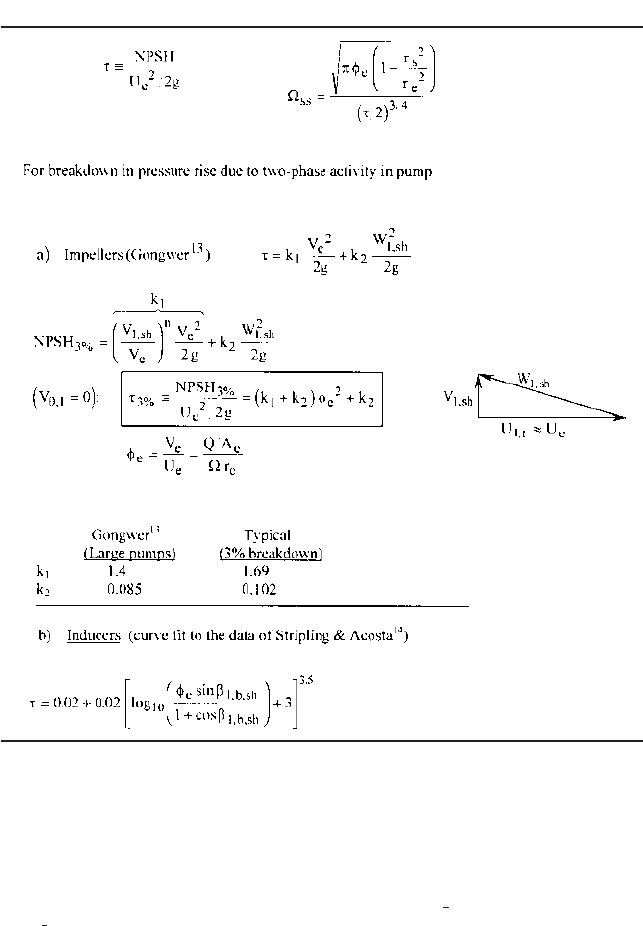
TABLE 1 NPSH correlations
2.1 CENTRIFUGAL PUMP THEORY 2.31
involves the exit flow coefficient or meridional velocity ratio f
i
V
m,2
/U
2
, the lower curve
of Figure 12 being for typical values of this quantity. The “openness” factor e allows for
blockage due to blade thickness and to the buildup of boundary layers on the surfaces of
the passageways (blades and hub and shroud).The value of e is generally between 0.8 and
0.9, the higher figure applying to larger machines. For axial-flow impellers or propellers
and inducers, a choice of the hub-to-tip radius ratio at the exit defines the passage width
instead. This ratio decreases with specific speed from about at the right end of Figure
12 to or less at the highest specific speeds.
d) Hub and shroud profiles. With the eye and the outlet sizing established, the two are
connected by specifying the hub and shroud profiles. Some texts illustrate the variation
of hub and shroud profiles with specific speed
15
. Although these are excellent guidelines
coming from experience, what follows is the approach one would take to synthesize these
1
3
2
3