Pump Handbook by Igor J. Karassik, Joseph P. Messina, Paul Cooper, Charles C. Heald - 3rd edition
Подождите немного. Документ загружается.


Centrifugal
pumpS
C•H•A•P•T•E•R•2

PAUL COOPER
2.3
SECTION 2.1
CENTRIFUGAL PUMP
THEORY
INTRODUCTION______________________________________________________
A centrifugal pump is a rotating machine in which flow and pressure are generated
dynamically. The inlet is not walled off from the outlet as is the case with positive dis-
placement pumps, whether they are reciprocating or rotary in configuration. Rather, a cen-
trifugal pump delivers useful energy to the fluid or “pumpage” largely through velocity
changes that occur as this fluid flows through the impeller and the associated fixed pas-
sageways of the pump; that is, it is a “rotodynamic” pump. All impeller pumps are rotody-
namic, including those with radial-flow, mixed-flow, and axial-flow impellers: the term
“centrifugal pump” tends to encompass all rotodynamic pumps.
Although the actual flow patterns within a centrifugal pump are three-dimensional
and unsteady in varying degrees, it is fairly easy, on a one-dimensional, steady-flow basis,
to make the connection between the basic energy transfer and performance relationships
and the geometry or what is commonly termed the “hydraulic design” (more properly the
“fluid dynamical design”) of impellers and stators or stationary passageways of these
machines.
In fact, disciplined one-dimensional thinking and analysis enables one to deduce pump
operational characteristics (for example, power and head versus flow rate) at both the opti-
mum or design conditions and off-design conditions. This enables the designer and the
user to judge whether a pump and the fluid system in which it is installed will operate
smoothly or with instabilities.The user should then be able to understand the offerings of
a pump manufacturer, and the designer should be able to provide a machine that opti-
mally fits the user’s requirements.

2.4 CHAPTER 2
The complexities of the flow in a centrifugal pump command attention when the
energy level or power input for a given size becomes relatively large. Fluid phenomena
such as recirculation, cavitation, and pressure pulsations become important; “hydraulic”
and mechanical interactions
—
involving stress, vibration, rotor dynamics, and the associ-
ated design approaches, as well as the materials used
—
become critical; and operational
limits must be understood and respected.
NOMENCLATURE ____________________________________________________
NOTE: The units for each quantity defined are as stated in this nomenclature, unless oth-
erwise specifically stated in the text, equations, figures, or tables.
A area, in
2
(mm).
a constant of the diffuser or volute configuration in Pfleiderer’s
slip relation.
a radius of impeller disk, ft (m), r
t,2
.
A
p
area of flow passage normal to the flow direction, ft
2
(m
2
).
b width of an impeller or other bladed passage in the meridional
plane, ft (m).
NOTE: When dealing with radial thrust, b
2
includes also the thickness of the shrouds.
C
p
specific heat of liquid being pumped, Btu/(lbm-degF);
[kcal/(kg-degC)].
c or V absolute velocity, ft/sec (m/s).
D diameter; unless otherwise subscripted impeller exit diameter,
ft (m).
d diameter, ft (m).
D
h
hydraulic diameter of flow passage ( 4A
p
/ ), ft (m).
F thrust force, lbf (N).
g acceleration due to gravity, 32.174 ft/sec
2
(9.80665 m/s
2
) at
earth sea level.
g
o
constant in Newton’s Second Law, 32.174 (lbm-ft)/(lbf-sec
2
).
(There is no SI equivalent; use the dimensionless constant 1 in
place of g
o
in SI computations.)
{g
p
} set of fluid properties associated with gas-handling phenomena
H head of liquid column, ft (m) (Eq. 3); can also have the same
meaning as the change in head H (that is, the same meaning
as “pump head”).
H change in head across pump or pump stage, also called the
“pump head” or “total dynamic head” ft (m).
H the small reduction in pump head (usually 3%) in testing for
NPSHR, ft (m).
H
e
H
i,
the ideal head for an infinite number of blades that pro-
duce no blockage.
H
i
ideal head [ H g(H
L
)], ft (m) (Eq. 15b); sometimes called the
“input head.”
H
L
head loss, ft (m).
gH
L
all losses in the main flow passages from pump inlet to pump
outlet, ft (m).
h static enthalpy in Btu/lbm times g
o
J,ft
2
/sec
2
; (or in kcal/kg times
J, m
2
/s
2
J/kg).

2.1 CENTRIFUGAL PUMP THEORY 2.5
h
sv
or NPSH net positive suction head, ft (m).
ID inner diameter.
J the mechanical equivalent of heat, 778 ft-lbf/Btu
(4184 N-m/kcal).
/ blade, vane, or passage arc length, ft (m).
M or T torque, lbf-ft (N-m).
m distance in streamwise direction in meridional plane (Figure
14), in or ft (m).
mass flow rate, lbf-sec/ft (kg/s), rQ.
MCSF or Q
min
minimum continuous stable flow, ft
3
/sec (m
3
/s).
N or n rotative speed of the impeller, rpm.
NPSH or h
sv
net positive suction head, ft (m).
NPSHA or NPSH
A
available NPSH.
NPSHR or NPSH
R
required NPSH to prevent significant loss ( 3%) of pump p or
to protect the pump against cavitation damage, whichever is
greater.
NPSH3% or NPSH
3%
required NPSH to prevent significant loss ( 3%) of pump p;
this is the “performance NPSH” defined in Section 2.3.1.
n
b
or Z
i
number of impeller blades.
n
q
specific speed in rpm, m
3
/s, m units (Eq. 38b) N
s
/51.64 (Eq. 39c).
n
v
or Z
d
number of vanes in diffuser or stator.
N
s
or N
s,(US)
or n
s
specific speed in rpm, gpm, ft units (Eq. 38a).
N
ss
or S suction specific speed in rpm, gpm, ft units (Eq. 42).
OD outer diameter.
P total pressure, lbf/ft
2
(Pa).
p pressure, lbf/ft
2
[Pa (N/m
2
)] ( “static pressure”).
p pressure rise, lbf/ft
2
(Pa).
p
L
pressure loss, lbf/ft
2
(Pa).
p
L, i
impeller pressure loss from its inlet to the point of interest,
lbf/ft
2
(Pa).
p
L, i I/L
pressure loss p
L, i
in impeller plus pressure loss in inlet passage,
lbf/ft
2
(Pa).
gp
L
all losses in the main flow passages from pump inlet to pump
outlet, lbf/ft
2
(Pa).
p
v
or p
vp
vapor pressure of liquid being pumped, lbf/ft
2
(Pa).
P
I
power delivered to all fluid flowing through the impeller,
ft-lbf/sec (kW).
P
S
shaft power, ft-lbf/sec (kW).
perimeter of flow passage cross section normal to the flow direc-
tion, ft (m).
Q volume flow rate or, more conveniently, “flow rate” or “capacity,”
ft
3
/sec (m
3
/s).
Q
DR
flow rate below which discharge recirculation exists, ft
3
/sec
(m
3
/s).
Q
L
leakage from impeller exit to inlet, ft
3
/sec (m
3
/s).
Q
min
or MCSF minimum continuous stable flow rate, ft
3
/sec (m
3
/s).
Q
R
flow rate below which recirculation exists, ft
3
/sec (m
3
/s).
m
#
2.6 CHAPTER 2
Q
SR
flow rate below which suction recirculation exists, ft
3
/sec (m
3
/s).
Q3D (quasi-3D) quasi-three dimensional.
R radius of curvature of meridional streamline, ft (m) (Figures 13,
14, and 25).
r radial distance from axis of rotation, ft (m).
r
b
radial distance from axis of rotation to center of circle defining
impeller passage width, ft (m) (Figures 13 and 25).
r
e
maximum value of r within the “eye plane.” (Figures 13 and 25).
s width of gap between impeller disk and adjacent casing wall,
ft (m).
S N
ss
, suction specific speed in rpm, gpm, ft units (Eq. 42).
sp. gr. specific gravity, namely, the ratio of liquid density to that of
water at 60°F (15.6°C).
{S} set of flow properties associated with solids in the pumpage
T axial thrust, lbf (N).
T or T or M torque, lbf-ft (N-m).
T temperature, °F or °R (°C or °K).
T
c
temperature rise due to compression, °F (°C).
t time, sec (s).
t blade or vane thickness, ft (m).
u internal energy in Btu/lbm multiplied by g
o
J,ft
2
/sec
2
; (or in
kcal/kg times J,m
2
/s
2
).
U tangential speed r of the point on the impeller at radius r,
ft/sec (m/s).
U
e
the value of U at the maximum radial location r
e
within the “eye
plane.”
V volume, ft
3
(m
3
).
V or c absolute velocity of fluid, ft/sec (m/s).
V
e
the average value of the meridional velocity component V
m
in
the eye ( Q/A
e
), ft/sec (m/s).
V
s
slip velocity (Figure 15), ft/sec (m/s).
W or w velocity of fluid relative to rotating impeller, ft/sec (m/s).
W
g
the one-dimensional value of W that would exist if there were
no slip.
w
1
throat width (Figure 21), ft (m).
y transformed distance along blade from trailing edge (Figure 19),
in or ft (m).
z axial distance in polar coordinate system, ft (m).
Z or Z
e
elevation coordinate, ft (m).
Z
d
or n
v
number of vanes in diffuser or stator.
Z
i
or n
b
number of impeller blades.
a angle of the absolute velocity vector from the circumferential
direction.
b angle of the relative velocity vector or impeller blade in the
plane of the velocity diagram (as seen, for example, in Figure 3)
from the circumferential (tangential) direction.
2.1 CENTRIFUGAL PUMP THEORY 2.7
g fluid weight density, lbf/ft
3
(N/m
3
) rg. (1N 1 kg-m/s
2
).
= clearance, ft (m)
*
displacement thickness of the boundary layer, ft (m).
0
*
displacement thickness of the zero-pressure-gradient boundary
layer, ft (m), ( 0.002 / for turbulent boundary layers at n 1
cs in typical centrifugal pumps).
e absolute roughness height, ft (m)
e
2
fraction of impeller discharge meridional area (that is, the area
normal to the velocity component V
m,2
) that is not blocked by the
thickness of the blades and the boundary layer displacement
thickness on blades and on hub and shroud surfaces.
e
2,b
fraction of the circumference at the exit of the impeller that is
not blocked by the thickness of the blades and boundary layer
displacement thickness on blades. (See computation in Table 4.)
h h
p
pump efficiency; or a component efficiency (different sub-
script, Eqs. 8–11).
u rotational polar coordinate or central angle about the impeller
axis, radians.
NOTE: In a polar-coordinate description of impeller blades or stationary vanes, u becomes
the construction angle and is usually regarded as positive in the direction of the blade
development from inlet to exit of the impeller or other blade row.
m slip factor V
s
/U
2
(1 h
0
, where h
0
is the slip factor as
defined by Busemann
18
.)
m absolute viscosity, lbf-sec/ft
2
(Pa-s or N-s/m
2
); often quoted in cen-
tipoises, abbreviated to “cp” (1 cp 0.001 Pa-s). [(m in cp) sp.
gr. (n in cs).]
n kinematic viscosity ( m/r), ft
2
/sec (m
2
/s); often quoted in
centistokes, abbreviated to “cs” (1 cs 1 mm
2
/s). [(n in cs)
(m in cp)/sp. gr.
r fluid mass density, lbf-sec
2
/ft
4
(kg/m
3
), g/g.
s solidity (Eq. 53).
s Thoma’s cavitation parameter h
sv
/H.
T or T or M torque, lbf-ft (N-m).
f flow coefficient.
f
e
V
e
/U
e
impeller inlet or eye flow coefficient.
f
i
(or f
i,2
) impeller exit flow coefficient V
m,2
/U
2
(Figure 12).
c head coefficient (Figure 12); stream function (Figure 14).
c
i
ideal head coefficient [ c
i,2
V
u,2
/U
2
for zero inlet swirl
(V
u,1
0)].
c
i,2
V
u,2
/U
2
[ c
i
for zero inlet swirl (V
u,1
0)].
angular speed of the impeller in radians per second (1/s) Np/30.
s
universal specific speed (unitless) (Eq. 37) N
s
/2733 (Eq. 38a)
n
q
/52.92 (Eq. 38b).
ss
universal suction specific speed (unitless) (Eq. 41) N
ss
/2733
(Eq. 42).
{2-ph} set of fluid properties associated with vaporization
2.8 CHAPTER 2
Subscripts
b impeller blade.
D drag due to disk friction, bearings, and seals.
DF disk friction.
d discharge flange or exit (ex) of the pump.
e at the “eye” of the impeller. The “eye” is the throat (minimum-
diameter point) at the entrance into the impeller and is the
area defined by the “eye plane,” which is normal to the axis of
rotation. “e” can refer more specifically to the shroud or
maximum-diameter point within the eye, as with r
e
(Figure 13)
or U
e
. The inlet tips of the impeller blades are generally at or
near this location.
ex exit of diffuser or the discharge flange or port of the pump (d).
f the direction of the flow.
h hub.
i inner limit of region or gap (Tables 4 and 5)
i (or ideal) ideal.
i (or imp) impeller.
in (or s) pump inlet flange or port.
I/L inlet passage; that is, the passage from the pump inlet flange or
port to the impeller.
I input to fluid.
L losses.
m “mechanical” (pertaining to efficiency, Eq. 9).
m component of velocity in the meridional plane (that is, the axial-
radial plane containing the axis of rotation).
mean the 50% or rms meridional streamline.
n normal or BEP value.
o outer limit of region or gap (Tables 4 and 5).
out pump outlet flange or port.
p pressure side of blade or passage.
R value of r at the impeller ring clearance.
S shaft.
s (or in) suction flange or inlet of the pump.
SE shockless entry (that is, inlet velocity vector aligned with blade
camber line).
s/o shut-off or zero flow rate Q.
r in the radial direction.
rms the 50% or mean meridional streamline.
s shaft.
s suction side of blade or passage.
s same meaning as sh and t.
sh shroud (also at the eye plane at inlet
—
and in general “t” at outlet).
stg stage.
T entry throat of volute or diffuser.

2.1 CENTRIFUGAL PUMP THEORY 2.9
t the tip or maximum radial position of the impeller blades at
inlet or outlet (same meaning as s and sh).
t tongue or cutwater.
u (see u, below).
v volumetric (pertaining to efficiency, Eq. 11).
v volute.
z in the axial direction.
u or u component of velocity in the circumferential direction (that is,
the tangential direction in the polar view that is perpendicular
to the axis of rotation).
1 impeller inlet at the blade leading edge
—
at the mean unless fur-
ther defined.
2 impeller outlet at the blade trailing edge
—
at the mean unless
further defined.
3 volute base circle or entrance to diffuser.
for an infinite number of blades that also produce zero blockage
of the flow.
Superscripts
¯¯ average value
ENERGY TRANSFER__________________________________________________
Hydraulics or fluid dynamics has the primary influence on the geometry of a rotodynamic
pump stage
—
of all the engineering disciplines involved in the design of the machine. It is
basic to the energy transfer or pumping process. Staging is also influenced by the other
disciplines, especially in high-energy pumps.The basic energy transfer relationships need
to be thoroughly understood to achieve a credible design and to understand the operation
of these machines. Action of the mechanical input shaft power to effect an increase in the
of energy of the pumpage is governed by the first law of thermodynamics. Realization of
that energy in terms of pump pressure rise or head involves losses and the second law of
thermodynamics.
The First Law of Thermodynamics Fluid flow, whether liquid or gas, through a cen-
trifugal pump is essentially adiabatic, heat transfer being negligible in comparison to the
other forms of energy involved in the energy transfer process. (Yet, even if the process were
not adiabatic, the density of a liquid is only weakly dependent on temperature.) Further,
while the delivery of energy to fluid by rotating blades is inherently unsteady (varying
pressure from blade to blade as viewed in an absolute reference frame), the flow across
the boundaries of a control volume surrounding the pump is essentially steady, and the
first law of thermodynamics for the pump can be expressed in the form of the adiabatic
steady-flow energy equation (Eq. 1) as follows:
where (1) h u
p
r
P
S
m
#
cah
V
2
2
gZ
e
b
out
ah
V
2
2
gZ
e
b
in
d
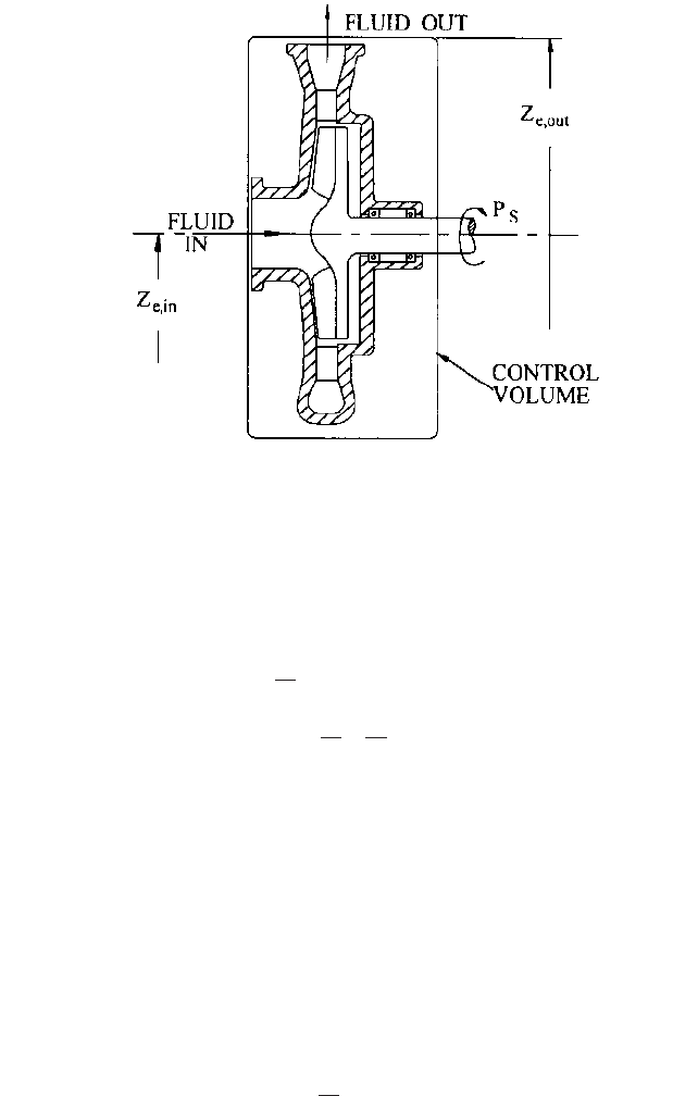
2.10 CHAPTER 2
FIGURE 1 Energy transfer in a centrifugal pump
Here, shaft power P
s
is transformed into fluid power, which is the mass flow rate times
the change in the total enthalpy (which includes static enthalpy, velocity energy per unit
mass, and potential energy due to elevation in a gravitational field that produces acceler-
ation at rate g) from inlet to outlet of the control volume (Figure 1).
When dealing with essentially incompressible liquids, the shaft power is commonly
expressed in terms of “head” and mass flow rate, as in Eq. 2:
(2)
where (3)
The change in H is called the “head” H of the pump; and, because H (Eq. 3) includes the
velocity head V
2
/2g and the elevation head Z
e
at the point of interest, H is often called the
“total dynamic head.” H is often abbreviated to simply “H” and is the increase in height
of a column of liquid that the pump would create if the static pressure head p/rg and the
velocity head V
2
/2g were converted without loss into elevation head Z
e
at their respective
locations at the inlet to and outlet from the control volume; that is, both upstream and
downstream of the pump.
The Second Law of Thermodynamics: Losses and Efficiency As can be seen from
Eq. 2, not all of the mechanical input energy per unit mass (that is, the shaft power per
unit of mass flow rate) ends up as useful pump output energy per unit mass gH. Rather,
losses produce an internal energy increase u (accompanied by a temperature increase)
in addition to that due to any heat transfer into the control volume. This fact is due to the
second law of thermodynamics and is expressed for pumps in Eq 4:
(4)g¢H 6
P
S
m
#
or h 6 1
H
p
rg
V
2
2g
Z
e
P
S
m
#
g¢H ¢u
m
#
2.1 CENTRIFUGAL PUMP THEORY 2.11
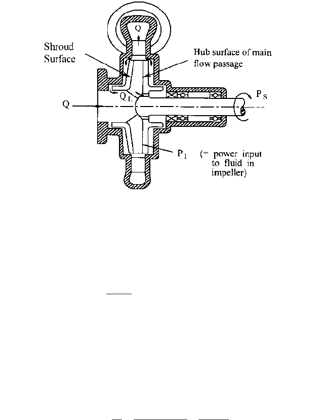
FIGURE 2 Determining component efficiencies. (This is a meridional view.)
where
The losses in the pump are quantified by the overall efficiency h, which must be less
than unity and is expressed in Eq. 5:
(5)
It should be pointed out here that real liquids undergo some compression
—
which is
accompanied by a reversible increase in the temperature T
c
of the liquid
—
called the
“heat of compression.” This portion of the actual total temperature rise T is in addition
to that arising from losses and must therefore be taken into account when determining
efficiency from measurements of the temperature rise of the pumpage.
1
See the discussion
on this subject in Section 2.3.1.
To pinpoint the losses, it is convenient to deal with them in terms of “component effi-
ciencies.” For the typical shrouded- or closed-impeller pump shown in Figure 2, Eq. 5 can
be rewritten as follows:
(6)
Noting that
(7)
and
one may rewrite Eq. 6 as follows:
H
i
Ideal Head
m
#
rQ
P
i
g¢H
i
1m
#
m
#
L
2
h
P
I
P
S
g¢H1m
#
m
#
L
2
P
I
m
#
m
#
m
#
L
h
g¢Hm
#
P
S
Overall Pump Efficiency
m
#
rQ