Power electronic handbook
Подождите немного. Документ загружается.

298 F. L. Luo and H. Ye
+
−
V
IN
i
IN
S
L
1
R
D
3
V
O
+
−
i
O
D
1
D
2
C
2
−
+
C
3
−
+
C
1
−
+
L
2
L
3
D
4
D
5
FIGURE 14.63 N/O CBC three-stage circuit.
and
I
O
=
I
I
1/(1 −k)
3
−1
The voltage transfer gain is
M
3
=
V
O
V
I
=
1
1 −k
3
−1 (14.171)
The variation ratio of the output voltage v
O
is
ε =
v
O
/2
V
O
=
k
2RfC
3
(14.172)
N/O CBC additional circuit is shown in Fig. 14.64. Its
output voltage and current are
V
O
=
2
1 −k
−1
V
I
=
1 +k
1 −k
V
I
and
I
O
=
1 −k
1 +k
I
I
V
IN
+
−
S
D
11
R
C
1
V
O
−
+
i
O
i
IN
D
1
L
1
D
12
C
12
C
11
FIGURE 14.64 N/O CBC additional circuit.
The voltage transfer gain is
M
A
=
V
O
V
I
=
1 +k
1 −k
(14.173)
The variation ratio of the output voltage v
O
is
ε =
v
O
/2
V
O
=
k
2RfC
12
(14.174)
N/O CBC additional two-stage circuit is shown in
Fig. 14.65. Its output voltage and current are
V
O
=
2
1
1 −k
2
−1
V
I
and
I
O
=
I
I
2
1/(1 −k)
2
−1
The voltage transfer gain is
M
A2
=
V
O
V
I
= 2
1
1 −k
2
−1 (14.175)
The variation ratio of the output voltage v
O
is
ε =
v
O
/2
V
O
=
k
2RfC
12
(14.176)
N/O CBC additional three-stage circuit is shown in
Fig. 14.66. Its output voltage and current are
V
O
=
2
1
1 −k
3
−1
V
I
and
I
O
=
I
I
2
1/(1 −k)
3
−1
14 DC/DC Conversion Technique and 12 Series Luo-converters 299
V
IN
+
−
S
R
C
1
C
2
C
12
V
O
−
+
i
O
i
IN
D
1
D
2
D
3
D
11
D
12
L
1
L
2
C
11
FIGURE 14.65 N/O CBC additional two-stage circuit.
V
IN
+
−
S
R
C
1
C
2
C
3
C
12
V
O
−
+
i
O
i
IN
D
1
D
3
D
5
D
2
D
4
D
11
D
12
L
1
L
2
L
3
C
11
FIGURE 14.66 N/O CBC additional three-stage circuit.
The voltage transfer gain is
M
A3
=
V
O
V
I
= 2
1
1 −k
3
−1 (14.177)
The variation ratio of the output voltage v
O
is
ε =
v
O
/2
V
O
=
k
2RfC
12
(14.178)
14.6 Ultra-lift Luo-converters
Ultra-lift (UL) Luo-converter performs very high voltage
transfer gain conversion. Its voltage transfer gain is the product
of those of VL Luo-converter and SL Luo-converter.
We know that the gain of P/O VL Luo-converters (as in
Eq. (14.52)) is
M =
V
O
V
I
=
k
h(n)
[n +h(n)]
1 −k
where n is the stage number, h(n) (as in Eq. (14.56)) is the
Hong function.
h(n) =
1 n = 0
0 n > 0
(from Eq. (14.32)) n = 0 for the elementary circuit with the
voltage transfer gain
M
E
=
V
O
V
I
=
k
1 −k
The voltage transfer gain of P/O SL Luo-converters is
M =
V
O
V
I
=
j + 2 − k
1 −k
n
(14.179)
where n is the stage number, j is the multiple-enhanced num-
ber. n = 1 and j = 0 for the elementary circuit with gain (as
in Eq. (14.131))
M
E
=
V
O
V
I
=
2 −k
1 −k
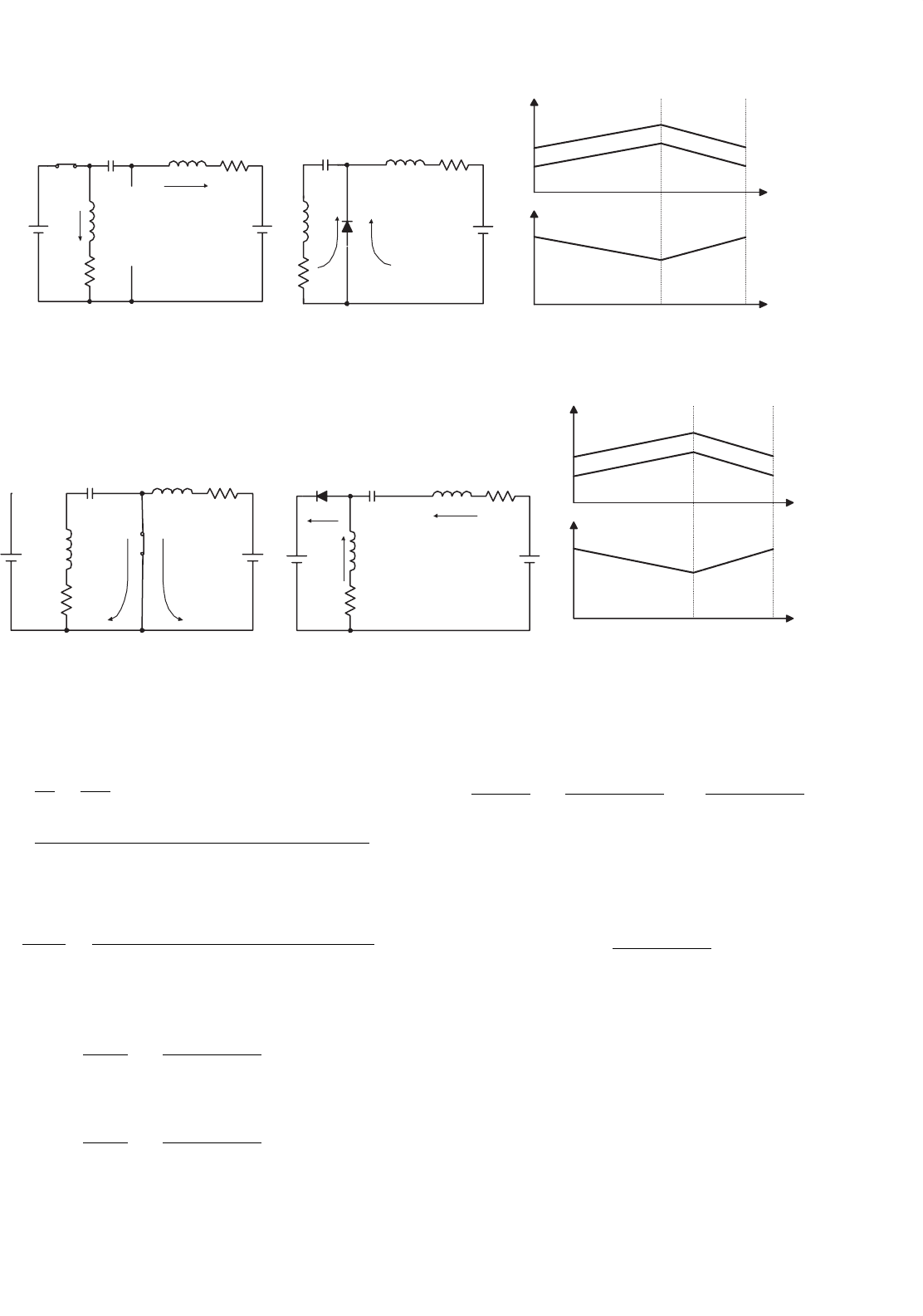
The circuit diagram of UL Luo-converter is shown in
Fig. 14.67a, which consists of one switch S, two inductors L
1
and L
2
, two capacitors C
1
and C
2
, three diodes, and the
load R. Its switch-on equivalent circuit is shown in Fig. 14.67b.
Its switch-off equivalent circuit for the continuous conduc-
tion mode is shown in Fig. 14.67c and switch-off equivalent
circuit for the discontinuous conduction mode is shown in
Fig. 14.67d.
14.6.1 Continuous Conduction Mode
Referring to Figs. 14.67b and c, we have got the current i
L1
increases with the slope +V
I
/L
1
during switch on, and
300 F. L. Luo and H. Ye
C
1
C
1
+
−
L
1
L
1
L
1
L
1
S
V
I
+
−
V
I
V
C1
i
I
i
I
i
L1
i
L1
i
L1
i
L1
+
−
C
1
C
1
V
C1
+
−
V
C1
+
−
V
C1
+
−
i
C1
i
C1
i
C1
i
C1
D
1
C
2
C
2
V
O
R
R
R
R
+
−
V
O
+
−
V
O
+
−
V
O
+
−
V
C2
+
−
V
C2
+
−
C
2
V
C2
+
−
C
2
V
C2
+
−
i
C2
i
C2
i
C2
i
C2
i
O
i
O
i
O
i
O
D
2
D
3
V
1
V
1
V
1
V
1
L
2
L
2
L
2
L
2
i
L2
i
L2
i
L2
i
L2
(a) (b)
(c) (d)
FIGURE 14.67 Ultra-lift (UL) Luo-converter: (a) circuit diagram; (b) switch on; (c) switch off in CCM; and (d) switch off in DCM.
decreases with the slope −V
1
/L
1
during switch off. In the
steady state, the current increment is equal to the decrement
in a whole period T. The relation below is obtained
kT
V
I
L
1
= (1 −k)T
V
1
L
1
(14.180)
Thus,
V
C1
= V
1
=
k
1 −k
V
I
(14.181)
The current i
L2
increases with the slope +(V
I
−V
1
)/L
2
dur-
ing switch on, and decreases with the slope −(V
1
− V
O
)/L
2
during switch off. In the steady state, the current increment
is equal to the decrement in a whole period T. We obtain the
relation below
kT
V
I
+V
1
L
2
= (1 −k)T
V
O
−V
1
L
2
(14.182)
V
O
= V
C2
=
2 −k
1 −k
V
1
=
k
1 −k
2 −k
1 −k
V
I
=
k(2 − k)
(1 −k)
2
V
I
(14.183)
I
O
=
(1 −k)
2
k(2 − k)
I
I
(14.184)
The voltage transfer gain is
M =
V
O
V
I
=
k(2 − k)
(1 −k)
2
=
k
1 −k
2 −k
1 −k
= M
E−VL
×M
E−SL
(14.185)
From Eq. (14.185) we can see that the voltage transfer gain of
UL Luo-converter is very high which is the product of those of
TABLE 14.3 Comparison of various converters gains
k 0.2 0.33 0.5 0.67 0.8 0.9
Buck 0.2 0.33 0.5 0.67 0.8 0.9
Boost 1.25 1.5 2 3 5 10
Buck–Boost 0.25 0.5 1 2 4 9
VL Luo-converter 0.25 0.5 1 2 4 9
SL Luo-converter 2.25 2.5 3 4 6 11
UL Luo-converter 0.56 1.25 3 8 24 99
VL Luo-converter and SL Luo-converter. We list the transfer
gains of various converters in Table 14.3 for reference.
The variation of inductor current i
L1
is
i
L1
= kT
V
I
L
1
(14.186)
and its variation ratio is
ξ
1
=
i
L1
/2
I
L1
=
k(1 − k)
2
TV
I
2L
1
I
2
=
k(1 − k)
2
TR
2L
1
M
=
(1 −k)
4
TR
2(2 −k)fL
1
(14.187)
The variation of inductor current i
L2
is
i
L2
=
kTV
I
(1 −k)L
2
(14.188)
and its variation ratio is
ξ
2
=
i
L2
/2
I
L2
=
kTV
I
2L
2
I
2
=
kTR
2L
2
M
=
(1 −k)
2
TR
2(2 −k)fL
2
(14.189)

14 DC/DC Conversion Technique and 12 Series Luo-converters 301
The variation of capacitor voltage v
C1
is
v
C1
=
Q
C1
C
1
=
kTI
L2
C
1
=
kTI
O
(1 −k)C
1
(14.190)
and its variation ratio is
σ
1
=
v
C1
/2
V
C1
=
kTI
O
2(1 −k)V
1
C
1
=
k(2 − k)
2(1 −k)
2
fC
1
R
(14.191)
The variation of capacitor voltage v
C2
is
v
C2
=
Q
C2
C
2
=
kTI
O
C
2
(14.192)
and its variation ratio is
ε = σ
2
=
v
C2
/2
V
C2
=
kTI
O
2V
O
C
2
=
k
2fC
2
R
(14.193)
From the analysis and calculations, we can see that all vari-
ations are very small. A design example is that V
I
= 10 V,
L
1
= L
2
= 1 mH, C
1
= C
2
= 1 µF, R = 3000 , f = 50 kHz,
and conduction duty cycle k varies from 0.1 to 0.9. We then
obtain the output voltage variation ratio ε, which is less than
0.003. The output voltage is very smooth DC voltage nearly no
ripple.
14.6.2 Discontinuous Conduction Mode
Referring to Fig. 14.67d, we have got the current i
L1
decreases
to zero before t = T, i.e. the current becomes zero before
next time the switch turns on. The DCM operation condition
is defined as
ξ ≥ 1
or
ξ
1
=
k(1 − k)
2
TR
2L
1
M
=
(1 −k)
4
TR
2(2 −k)fL
1
≥ 1 (14.194)
The normalized impedance Z
N
is,
Z
N
=
R
fL
1
(14.195)
We define the filling factor m to describe the current exists
time. For DCM operation, 0 < m ≤ 1,
m =
1
ξ
1
=
2L
1
G
k(1 − k)
2
TR
=
2(2 −k)
(1 −k)
4
Z
N
(14.196)
kT
V
I
L
1
= (1 −k)mT
V
1
L
1
Thus,
V
C1
= V
1
=
k
(1 −k)m
V
I
(14.197)
We finally obtain the relation below
kT
V
I
+V
1
L
2
= (1 −k)T
V
O
−V
1
L
2
(14.198)
V
O
= V
C2
=
2 −k
1 −k
V
1
=
k(2 − k)
m(1 −k)
2
V
I
(14.199)
The voltage transfer gain in DCM is higher than that in
CCM.
M
DCM
=
V
O
V
I
=
k(2 − k)
m(1 −k)
2
=
M
CCM
m
with m < 1
(14.200)
14.7 Multiple-quadrant Operating
Luo-converters
Multiple-quadrant operating converters are the second-
generation converters. These converters usually perform
between two voltage sources: V
1
and V
2
. Voltage source V
1
is proposed positive voltage and voltage V
2
is the load volt-
age. In the investigation both voltages are proposed constant
voltage. Since V
1
and V
2
are constant values, voltage trans-
fer gain is constant. Our interesting research will concentrate
the working current, minimum conduction duty k
min
, and the
power transfer efficiency η.
Multiple-quadrant operating Luo-converters are the
second-generation converters and they have three modes:
• Two-quadrant DC/DC Luo-converter in forward opera-
tion;
•
Two-quadrant DC/DC Luo-converter in reverse opera-
tion;
• Four-quadrant DC/DC Luo-converter.
The two-quadrant DC/DC Luo-converter in forward opera-
tion has been derived from the positive output Luo-converter.
It performs in the first-quadrant Q
I
and the second-quadrant
Q
II
corresponding to the DC motor forward operation in
motoring and regenerative braking states.
The two-quadrant DC/DC Luo-converter in reverse opera-
tion has been derived from the N/O Luo-converter. It performs
in the third-quadrant Q
III
and the fourth-quadrant Q
IV
corre-
sponding to the DC motor reverse operation in motoring and
regenerative braking states.
The four-quadrant DC/DC Luo-converter has been derived
from the double output Luo-converter. It performs four-
quadrant operation corresponding to the DC motor forward
302 F. L. Luo and H. Ye
and reverse operation in motoring and regenerative braking
states.
In the following analysis the input source and output load
are usually constant voltages as shown, V
1
and V
2
. Switches
S
1
and S
2
in this diagram are power metal oxide semicon-
ductor field effect transistor (MOSFET) devices, and they are
driven by a PWM switching signal with repeating frequency
f and conduction duty k. In this paper the switch repeating
period is T = 1/f , so that the switch-on period is kT and
switch-off period is (1 − k)T. The equivalent resistance is R
for each inductor. During switch-on the voltage drop across
the switches and diodes are V
S
and V
D
respectively.
14.7.1 Forward Two-quadrant DC/DC
Luo-converter
Forward Two-quadrant (F 2Q) Luo-converter is shown in
Fig. 14.68. The source voltage (V
1
) and load voltage (V
2
) are
usually considered as constant voltages. The load can be a bat-
tery or motor back electromotive force (EMF). For example,
the source voltage is 42 V and load voltage is +14 V. There are
two modes of operation:
1. Mode A (Quadrant I): electrical energy is transferred
from source side V
1
to load side V
2
;
2. Mode B (Quadrant II): electrical energy is transferred
from load side V
2
to source side V
1
.
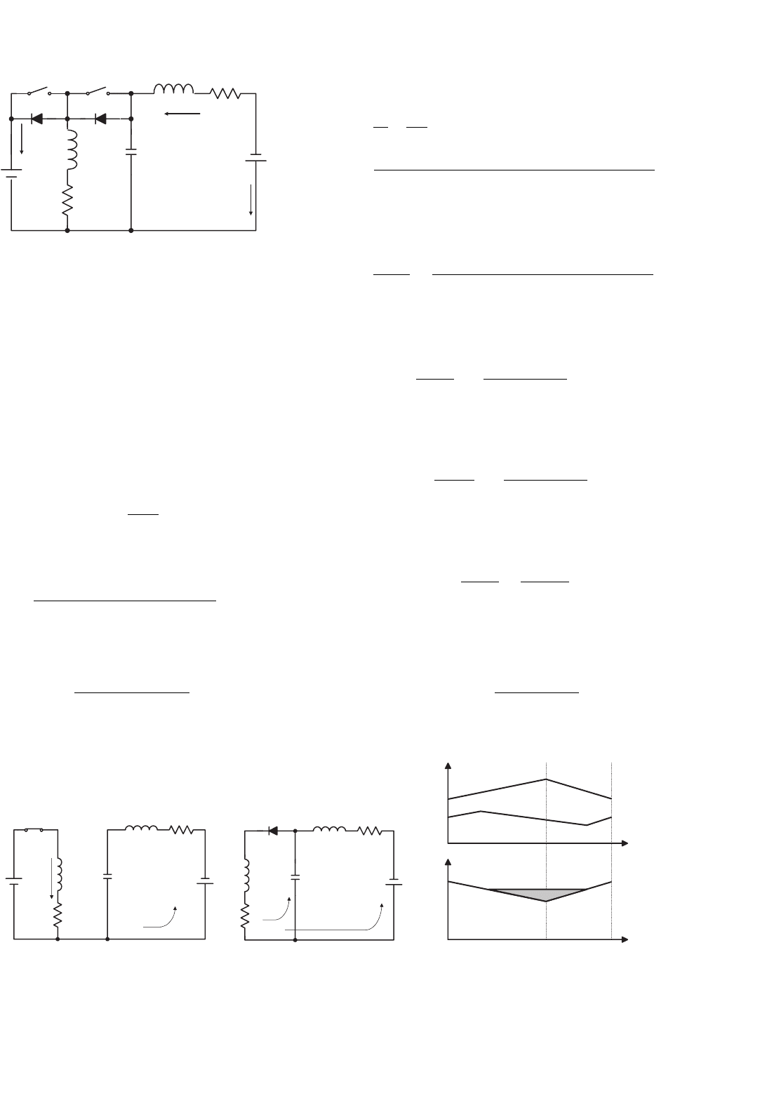
Mode A: The equivalent circuits during switch-on and -off
periods are shown in Figs. 14.69a and b. The typical output
voltage and current waveforms are shown in Fig. 14.69c. We
have the output current I
2
as
I
2
=
1 −k
k
I
1
(14.201)
and
I
2
=
V
1
−V
S
−V
D
−V
2
((1 −k)/k)
R
(k/(1 − k)) + ((1 − k)/k)
(14.202)
+
−
D
1
S
1
L
1
V
1
R
C
V
C
+−
S
2
L
2
R
V
2
+
−
I
1
I
2
D
2
FIGURE 14.68 Forward two-quadrant operating Luo-converter.
The minimum conduction duty k corresponding to I
2
= 0is
k
min
=
V
2
V
1
+V
2
−V
S
−V
D
(14.203)
The power transfer efficiency is
η
A
=
P
O
P
I
=
V
2
I
2
V
1
I
1
=
1
1+
(V
S
+V
D
)/V
2
(k/(1−k))+(RI
2
/V
2
)
1+((1−k)/k)
2
(14.204)
The variation ratio of capacitor voltage v
C
is
ρ =
v
C
/2
V
C
=
(1 −k)I
2
2fC(V
1
−RI
2
(1/(1 −k)))
(14.205)
The variation ratio of inductor current i
L1
is
ξ
1
=
i
L1
/2
I
L1
= k
V
1
−V
S
−RI
1
2fL
1
I
1
(14.206)
The variation ratio of inductor current i
L2
is
ξ
2
=
i
L2
/2
I
L2
= k
V
1
−V
S
−RI
1
2fL
2
I
2
(14.207)
The variation ratio of diode current i
D2
is
ζ
D2
=
i
D2
/2
I
L1
+I
L2
= k
V
1
−V
S
−RI
1
2fL(I
1
+I
2
)
= k
2
V
1
−V
S
−RI
1
2fLI
1
(14.208)
If the diode current becomes zero before S
1
switch on again,
the converter works in discontinuous region. The condition is
ζ
D2
= 1, i.e. k
2
=
2fLI
1
V
1
−V
S
−RI
1
(14.209)
Mode B: The equivalent circuits during switch-on and -off
periods are shown in Figs. 14.70a and b. The typical output
voltage and current waveforms are shown in Fig. 14.70c. We
have the output current I
1
as
I
1
=
1 −k
k
I
2
(14.210)
and
I
1
=
V
2
−(V
1
+V
S
+V
D
)((1 −k)/k)
R
(k/(1 − k)) + ((1 − k)/k)
(14.211)
The minimum conduction duty k corresponding to I
1
= 0is
k
min
=
V
1
+V
S
+V
D
V
1
+V
2
+V
S
+V
D
(14.212)
14 DC/DC Conversion Technique and 12 Series Luo-converters 303
V
1
+
−
S
1
L
1
L
1
R
R
V
C
+−
V
C
+−
L
2
L
2
R
R
V
2
+
−
V
2
v
C
+
−
i
L1
i
L1
i
L1
i
L2
i
L2
i
L2
S
2
D
2
D
2
C
C
t0
t0
i
v
(a) (b) (c)
FIGURE 14.69 Mode A: (a) switch on; (b) switch off; and (c) waveforms.
V
1
+
−
V
1
+
−
S
1
L
1
L
1
R
R
V
C
+−
V
C
+−
L
2
L
2
R
R
V
2
+
−
V
2
+
−
i
L1
i
L1
i
D1
i
L2
i
L2
S
2
D
1
D
1
C
C
v
C
i
L1
i
L2
t0
t0
i
v
(a) (b) (c)
FIGURE 14.70 Mode B: (a) switch on; (b) switch off; and (c) waveforms.
The power transfer efficiency
η
B
=
P
O
P
I
=
V
1
I
1
V
2
I
2
=
1
1 +((V
S
+V
D
)/V
1
) +(RI
1
/V
1
)[1 +((1 −k)/k)
2
]
(14.213)
The variation ratio of capacitor voltage v
C
is
ρ =
v
C
/2
V
C
=
kI
1
2fC[(V
2
/(1 −k)) − V
1
−RI
1
(k/(1 − k)
2
)]
(14.214)
The variation ratio of inductor current i
L1
is
ξ
1
=
i
L1
/2
I
L1
= k
V
2
−V
S
−RI
2
2fL
1
I
1
(14.215)
The variation ratio of inductor current i
L2
is
ξ
2
=
i
L2
/2
I
L2
= k
V
2
−V
S
−RI
2
2fL
2
I
2
(14.216)
The variation ratio of diode current i
D1
is
ζ
D1
=
i
D2
/2
I
L1
+I
L2
= k
V
2
−V
S
−RI
2
2fL(I
1
+I
2
)
= k
2
V
2
−V
S
−RI
2
2fLI
2
(14.217)
If the diode current becomes zero before S
2
switch on again,
the converter works in discontinuous region. The condition is
ζ
D1
= 1, i.e. k
2
=
2fLI
2
V
2
−V
S
−RI
2
(14.218)
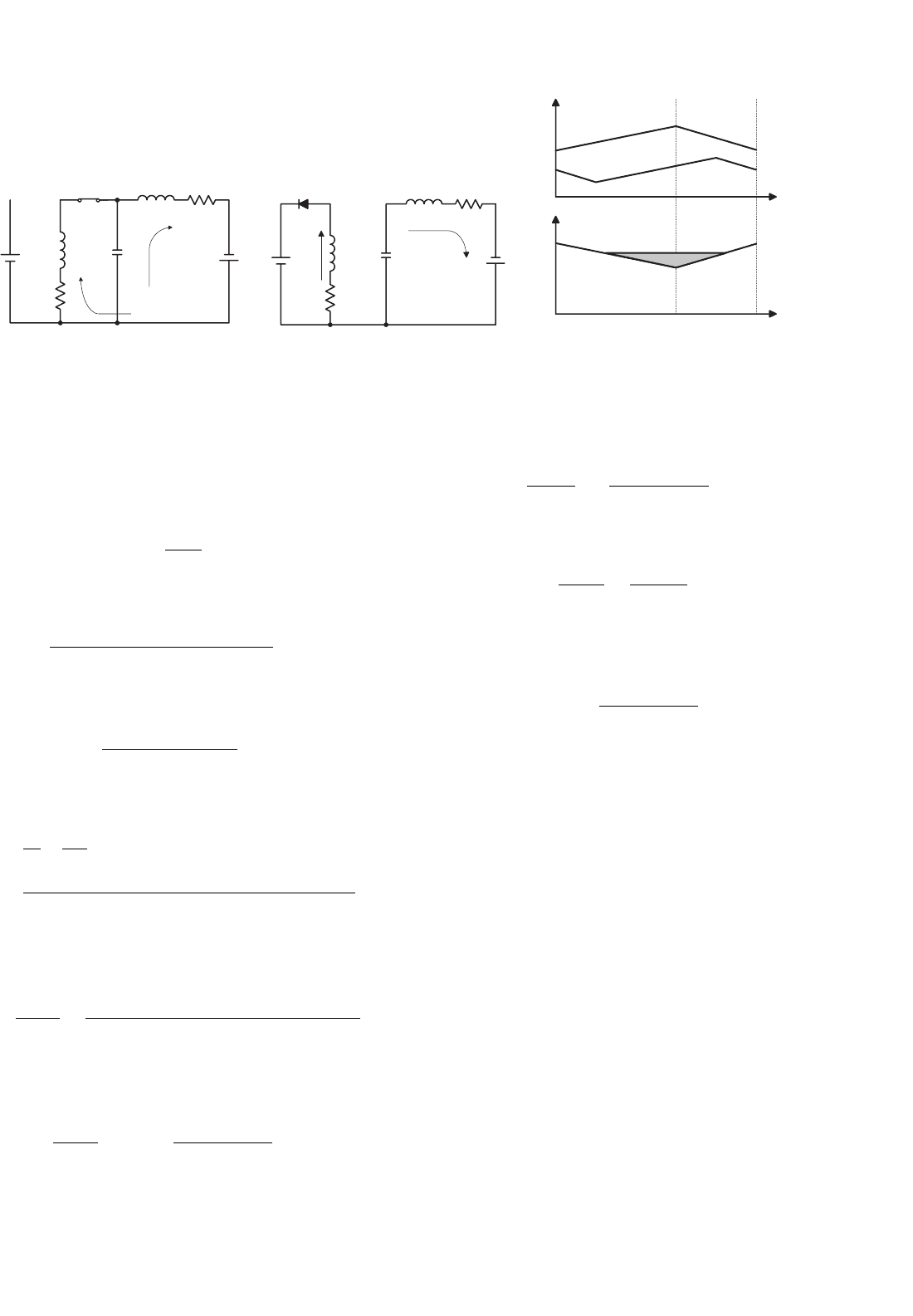
14.7.2 Two-quadrant DC/DC Luo-converter in
Reverse Operation
Reverse two-quadrant operating (R 2Q) Luo-converter is
shown in Fig. 14.71, and it consists of two switches with two
passive diodes, two inductors and one capacitor. The source
voltage (V
1
) and load voltage (V
2
) are usually considered as
constant voltages. The load can be a battery or motor back
EMF. For example, the source voltage is 42 V and load voltage
304 F. L. Luo and H. Ye
V
1
+
−
L
1
R
V
C
+
−
L
2
R
V
2
+
−
i
L2
D
1
I
1
I
2
S
1
S
2
C
D
2
FIGURE 14.71 Reverse two-quadrant operating Luo-converter.
is −14 V. There are two modes of operation:
1. Mode C (Quadrant III): electrical energy is transferred
from source side V
1
to load side −V
2
;
2. Mode D (Quadrant IV): electrical energy is transferred
from load side −V
2
to source side V
1
.
Mode C: The equivalent circuits during switch-on and -off
periods are shown in Figs. 14.72a and b. The typical output
voltage and current waveforms are shown in Fig. 14.72c. We
have the output current I
2
as
I
2
=
1 −k
k
I
1
(14.219)
and
I
2
=
V
1
−V
S
−V
D
−V
2
((1 −k)/k)
R
[
(1/(k(1 − k))) + ((1 − k)/k)
]
(14.220)
The minimum conduction duty k corresponding to I
2
= 0is
k
min
=
V
2
V
1
+V
2
−V
S
−V
D
(14.221)
V
1
+
−
S
1
L
1
L
1
R
R
C
V
C
+
−
C
V
C
V
C
+
−
R
R
L
2
L
2
D
2
+
−
V
2
+
−
V
2
i
L1
i
L1
i
L1
i
L2
i
L2
i
L2
A
v
i
t
t
0
0
(a) (b)
(c)
FIGURE 14.72 Mode C: (a) switch on; (b) switch off; and (c) waveforms.
The power transfer efficiency is
η
C
=
P
O
P
I
=
V
2
I
2
V
1
I
1
=
1
1 +((V
S
+V
D
)/V
2
)(k/(1 −k)) + (RI
2
/V
2
)[1 +(1/(1 − k))
2
]
(14.222)
The variation ratio of capacitor voltage v
C
is
ρ =
v
C
/2
V
C
=
kI
2
2fC
(k/(1 − k))V
1
−((RI
2
)/(1 −k)
2
)
(14.223)
The variation ratio of inductor current i
L1
is
ξ
1
=
i
L1
/2
I
L1
= k
V
1
−V
S
−RI
1
2fL
1
I
1
(14.224)
The variation ratio of inductor current i
D2
is
ζ
D2
= ξ
1
=
i
D2
/2
I
L1
= k
V
1
−V
S
−RI
1
2fL
1
I
1
(14.225)
The variation ratio of inductor current i
L2
is
ξ
2
=
i
L2
/2
I
2
=
k
16f
2
CL
2
(14.226)
If the diode current becomes zero before S
1
switch on again,
the converter works in discontinuous region. The condition is
ζ
D2
= 1, i.e. k =
2fL
1
I
1
V
1
−V
S
−RI
1
(14.227)
14 DC/DC Conversion Technique and 12 Series Luo-converters 305
V
1
+
−
V
1
+
−
S
2
L
1
L
1
D
1
D
1
R
R
CC
V
C
+
−
V
C
+
−
V
C
R
R
L
2
L
2
+
−
V
2
+
−
V
2
i
L1
i
L1
i
L1
i
L2
i
L2
i
L2
B
v
i
t
t
0
0
(a) (b) (c)
FIGURE 14.73 Mode D: (a) switch on; (b) switch off; and (c) waveforms.
Mode D: The equivalent circuits during switch-on and -off
periods are shown in Figs. 14.73a and b. The typical output
voltage and current waveforms are shown in Fig. 14.73c. We
have the output current I
1
as
I
1
=
1 −k
k
I
2
(14.228)
and
I
1
=
V
2
−(V
1
+V
S
+V
D
)((1 −k)/k)
R[(1/(k(1 −k))) + (k/(1 − k))]
(14.229)
The minimum conduction duty k corresponding to I
1
= 0is
k
min
=
V
1
+V
S
+V
D
V
1
+V
2
+V
S
+V
D
(14.230)
The power transfer efficiency is
η
D
=
P
O
P
I
=
V
1
I
1
V
2
I
2
=
1
1 +((V
S
+V
D
)/V
1
) +(RI
1
/V
1
)[(1/(1 −k)
2
) +(k/(1 − k))
2
]
(14.231)
The variation ratio of capacitor voltage v
C
is
ρ =
v
C
/2
V
C
=
kI
1
2fC
[
((1 −k)/k)V
1
+((RI
1
)/(k(1 − k)))
]
(14.232)
The variation ratio of inductor current i
L1
is
ξ
1
=
i
L1
/2
I
L1
= (1 −k)
V
2
−V
S
−RI
2
2fL
1
I
1
(14.233)
And the variation ratio of inductor current i
D1
is
ζ
D1
= ξ
1
=
i
D1
/2
I
L1
= k
V
2
−V
S
−RI
2
2fL
1
I
2
(14.234)
The variation ratio of inductor current i
L2
is
ξ
2
=
i
L2
/2
I
2
=
1 −k
16f
2
CL
2
(14.235)
If the diode current becomes zero before S
2
switch on again,
the converter works in discontinuous region. The condition is
ζ
D1
= 1, i.e. k =
2fL
1
I
2
V
2
−V
S
−RI
2
(14.236)
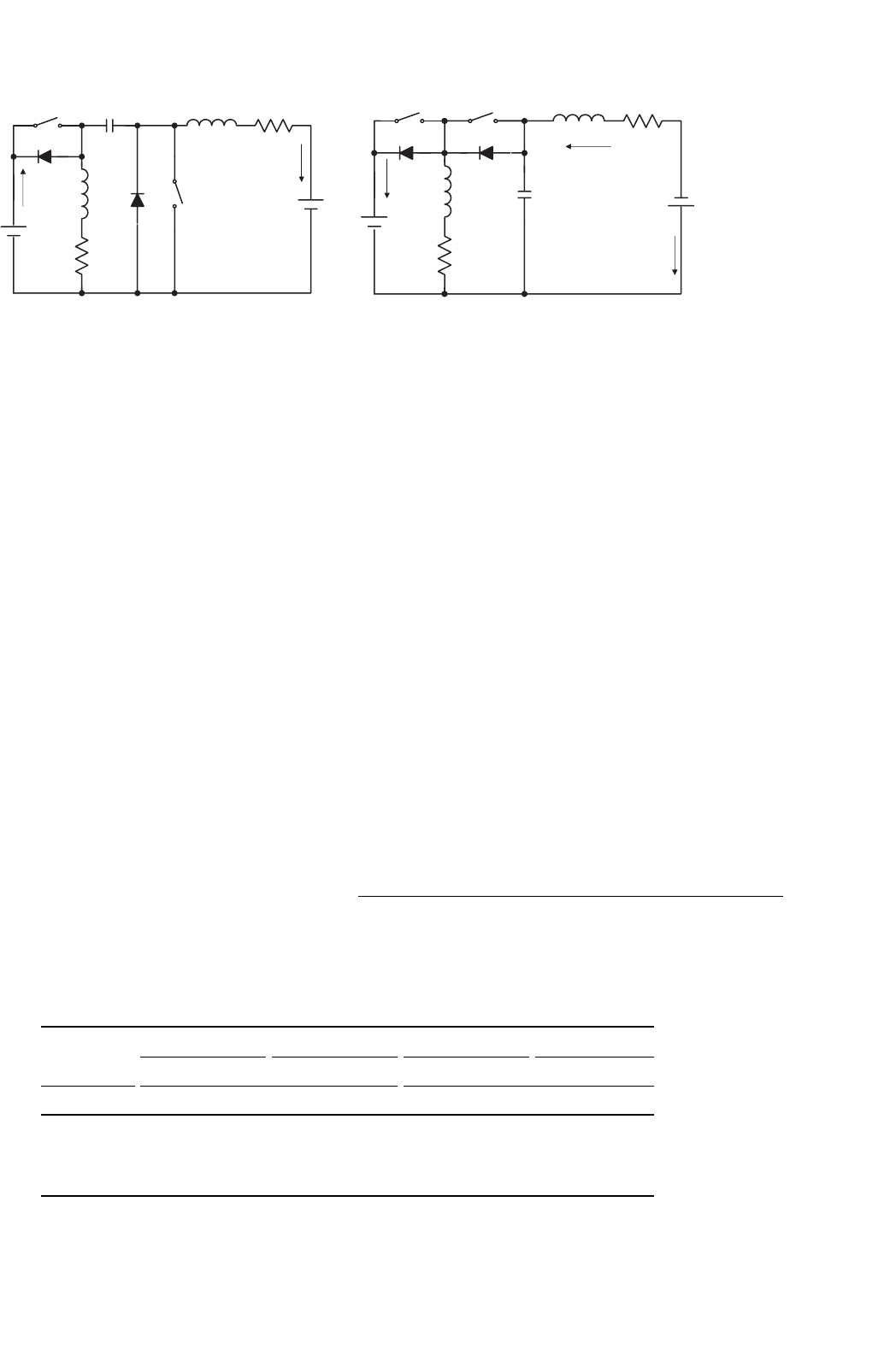
14.7.3 Four-quadrant DC/DC Luo-converter
Four-quadrant DC/DC Luo-converter is shown in Fig. 14.74,
which consists of two switches with two passive diodes, two
inductors, and one capacitor. The source voltage (V
1
) and
load voltage (V
2
) are usually considered as constant voltages.
The load can be a battery or motor back EMF. For example,
the source voltage is 42 V and load voltage is ±14 V. There are
four modes of operation:
1. Mode A (Quadrant I): electrical energy is transferred
from source side V
1
to load side V
2
;
2. Mode B (Quadrant II): electrical energy is transferred
from load side V
2
to source side V
1
;
3. Mode C (Quadrant III): electrical energy is transferred
from source side V
1
to load side −V
2
;
4. Mode D (Quadrant IV): electrical energy is transferred
from load side −V
2
to source side V
1
.
Each mode has two states: “on” and “off.” Usually, each
state is operating in different conduction duty k. The switches
306 F. L. Luo and H. Ye
V
1
+
−
V
1
+
−
S
2
S
2
S
1
S
1
I
1
I
1
I
2
I
2
L
1
L
1
D
1
D
1
D
2
D
2
R
C
C
V
C
+
V
C
+
−
−
R
R
R
L
2
L
2
−
+
V
2
+
−
V
2
i
L2
(a) (b)
FIGURE 14.74 Four-quadrant operating Luo-converter: (a) circuit 1 and (b) circuit 2.
are the power MOSFET devices. The circuit 1 in Fig. 14.74
implements Modes A and B, and the circuit 2 in Fig. 14.74
implements Modes C and D. Circuits 1 and 2 can changeover
by auxiliary switches (not in the figure).
Mode A: During state-on switch S
1
is closed, switch S
2
and
diodes D
1
and D
2
are not conducted. In this case inductor
currents i
L1
and i
L2
increase, and i
1
= i
L1
+ i
L2
. During
state-off switches S
1
,S
2
, and diode D
1
are off and diode D
2
is conducted. In this case current i
L1
flows via diode D
2
to
charge capacitor C, in the meantime current i
L2
is kept to
flow through load battery V
2
. The free-wheeling diode current
i
D2
= i
L1
+i
L2
. Mode A implements the characteristics of the
buck–boost conversion.
Mode B: During state-on switches S
2
is closed, switch S
1
and
diodes D
1
and D
2
are not conducted. In this case inductor cur-
rent i
L2
increases by biased V
2
, inductor current i
L1
increases
by biased V
C
. Therefore capacitor voltage V
C
reduces. During
state-off switches S
1
,S
2
, and diode D
2
are not on, and only
diode D
1
is on. In this case source current i
1
= i
L1
+i
L2
which
is a negative value to perform the regenerative operation.
Inductor current i
L2
flows through capacitor C, it is charged
by current i
L2
. After capacitor C, i
L2
then flows through the
source V
1
. Inductor current i
L1
flows through the source V
1
as well via diode D
1
. Mode B implements the characteristics
of the boost conversion.
Mode C: During state-on switch S
1
is closed, switch S
2
and
diodes D
1
and D
2
are not conducted. In this case inductor
TABLE 14.4 Switch’s status (the blank status means OFF)
Switch or diode Mode A (QI) Mode B (QII) Mode C (QIII) Mode D (QIV)
State-on State-off State-on State-off State-on State-off State-on State-off
Circuit Circuit 1 Circuit 2
S
1
ON ON
D
1
ON ON
S
2
ON ON
D
2
ON ON
currents i
L1
and i
L2
increase, and i
1
= i
L1
. During state-off
switches S
1
,S
2
, and diode D
1
are off and diode D
2
is con-
ducted. In this case current i
L1
flows via diode D
2
to charge
capacitor C and the load battery V
2
via inductor L
2
. The
free-wheeling diode current i
D2
= i
L1
= i
C
+ i
2
. Mode C
implements the characteristics of the buck–boost conversion.
Mode D: During state-on switches S
2
is closed, switch S
1
and diodes D
1
and D
2
are not conducted. In this case induc-
tor current i
L1
increases by biased V
2
, inductor current i
L2
decreases by biased (V
2
−V
C
). Therefore capacitor voltage V
C
reduces. Current i
L1
= i
C−on
+ i
2
. During state-off switches
S
1
,S
2
, and diode D
2
are not on, and only diode D
1
is on. In
this case source current i
1
= i
L1
which is a negative value
to perform the regenerative operation. Inductor current i
2
flows through capacitor C that is charged by current i
2
, i.e.
i
C−off
= i
2
. Mode D implements the characteristics of the
boost conversion.
Summary: The switch status is shown in Table 14.4.
The operation of all modes A, B, C, and D is same to the
description in Sections 14.7.1 and 14.7.2.
14.8 Switched-capacitor Multi-quadrant
Luo-converters
Switched-component converters are the third-generation
converters. These converters are made of only inductor
14 DC/DC Conversion Technique and 12 Series Luo-converters 307
S
1
V
H
D
1
D
2
S
2
S
8
S
4
V
L
C
1
C
2
C
3
D
3
S
9
S
10
S
6
S
7
D
4
D
5
+
−
+
−
+
−
+
−
+
−
i
H
i
L
S
3
D
6
D
8
D
10
D
9
S
5
FIGURE 14.75 Two-quadrant switched-capacitor DC/DC Luo-converter.
or capacitors. They usually perform in the systems between
two voltage sources: V
1
and V
2
. Voltage source V
1
is proposed
positive voltage and voltage V
2
is the load voltage that can
be positive or negative. In the investigation both voltages are
proposed constant voltage. Since V
1
and V
2
are constant val-
ues, so that voltage transfer gain is constant. Our interesting
research will concentrate on the working current and the
power transfer efficiency η. The resistance R of the capacitors
and inductor has to be considered for the power transfer
efficiency η calculation.
Reviewing the papers in the literature, we can find that
almost of the papers investigating the switched-component
converters are working in single-quadrant operation. Profes-
sor Luo and colleagues have developed this technique into
multi-quadrant operation. We describe these in this and next
sections.
Switched-capacitor multi-quadrant Luo-converters are the
third-generation converters, and they are made of only capac-
itors. Because these converters implement voltage-lift and
current-amplification techniques, they have the advantages of
high power density, high power transfer efficiency, and low
EMI. They have two modes:
• Two-quadrant switched-capacitor DC/DC Luo-converter;
• Four-quadrant switched-capacitor DC/DC Luo-converter.
The two-quadrant switched-capacitor DC/DC Luo-converter
in forward operation has been derived for the energy transmis-
sion of a dual-voltage system in two-quadrant operation. The
both, source and load voltages are positive polarity. It performs
in the first-quadrant Q
I
and the second-quadrant Q
II
corre-
sponding to the DC motor forward operation in motoring and
regenerative braking states.
The four-quadrant switched-capacitor DC/DC Luo-
converter has been derived for the energy transmission of a
dual-voltage system in four-quadrant operation. The source
voltage is positive and load voltage can be positive or negative
polarity. It performs four-quadrant operation corresponding
to the DC motor forward and reverse operation in motoring
and regenerative braking states.
From the analysis and calculation, the conduction duty k
does not affect the power transfer efficiency. It affects the input
and output power in a small region. The maximum output
power corresponds at k = 0.5.
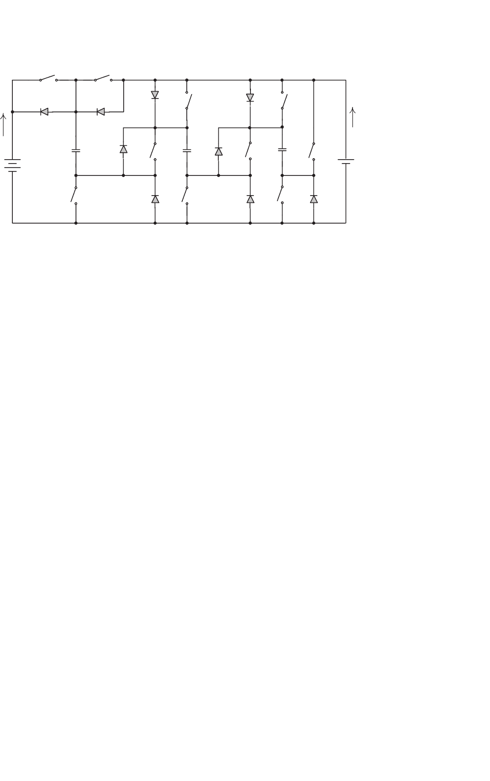
14.8.1 Two-quadrant Switched-capacitor
DC/DC Luo-converter
This converter is shown in Fig. 14.75. It consists of nine
switches, seven diodes, and three capacitors. The high source
voltage V
H
and low load voltage V
L
are usually considered
as constant voltages, e.g. the source voltage is 48 V and load
voltage is 14 V. There are two modes of operation:
• Mode A (Quadrant I): electrical energy is transferred
from V
H
side to V
L
side;
• Mode B (Quadrant II): electrical energy is transferred
from V
L
side to V
H
side.
Each mode has two states: “on” and “off.” Usually, each
state is operating in different conduction duty k. The switch-
ing period is T where T = 1/f , where f is the switching
frequency. The switches are the power MOSFET devices. The
parasitic resistance of all switches is r
S
. The equivalent resis-
tance of all capacitors is r
C
and the equivalent voltage drop of
all diodes is V
D
. Usually we select the three capacitors having
same capacitance C = C
1
= C
2
= C
3
. Some reference data are
useful: r
S
= 0.03 , r
C
= 0.02 , and V
D
= 0.5 V, f = 5 kHz,
and C = 5000 µF. The switch’s status is shown in Table 14.5.
For Mode A, state-on is shown in Fig. 14.76a: switches
S
1
and S
10
are closed and diodes D
5
and D
5
are con-
ducted. Other switches and diodes are open. In this case
capacitors C
1
, C
2
, and C
3
are charged via the circuit V
H
–
S
1
–C
1
–D
5
–C
2
–D
6
–C
3
–S
10
, and the voltage across capacitors