Power electronic handbook
Подождите немного. Документ загружается.

308 F. L. Luo and H. Ye
TABLE 14.5 Switch’s status (the blank status means OFF)
Switch or diode Mode A Mode B
State-on State-off State-on State-off
S
1
ON
D
1
ON
S
2
,S
3
,S
4
ON
D
2
,D
3
,D
4
ON
S
5
,S
6
,S
7
ON
D
5
,D
6
ON
S
8
,S
9
ON
S
10
ON ON
D
8
,D
9
,D
10
ON
C
1
, C
2
, and C
3
is increasing. The equivalent circuit resistance
is R
AN
= (2r
S
+ 3r
C
) = 0.12 , and the voltage deduction is
2V
D
= 1 V. State-off is shown in Fig. 14.76b: switches S
2
,S
3
,
and S
4
are closed and diodes D
8
,D
9
, and D
10
are conducted.
Other switches and diodes are open. In this case capacitor
C
1
(C
2
and C
3
) is discharged via the circuit S
2
(S
3
and S
4
)–
V
L
–D
8
(D
9
and D
10
)–C
1
(C
2
and C
3
), and the voltage across
capacitor C
1
(C
2
and C
3
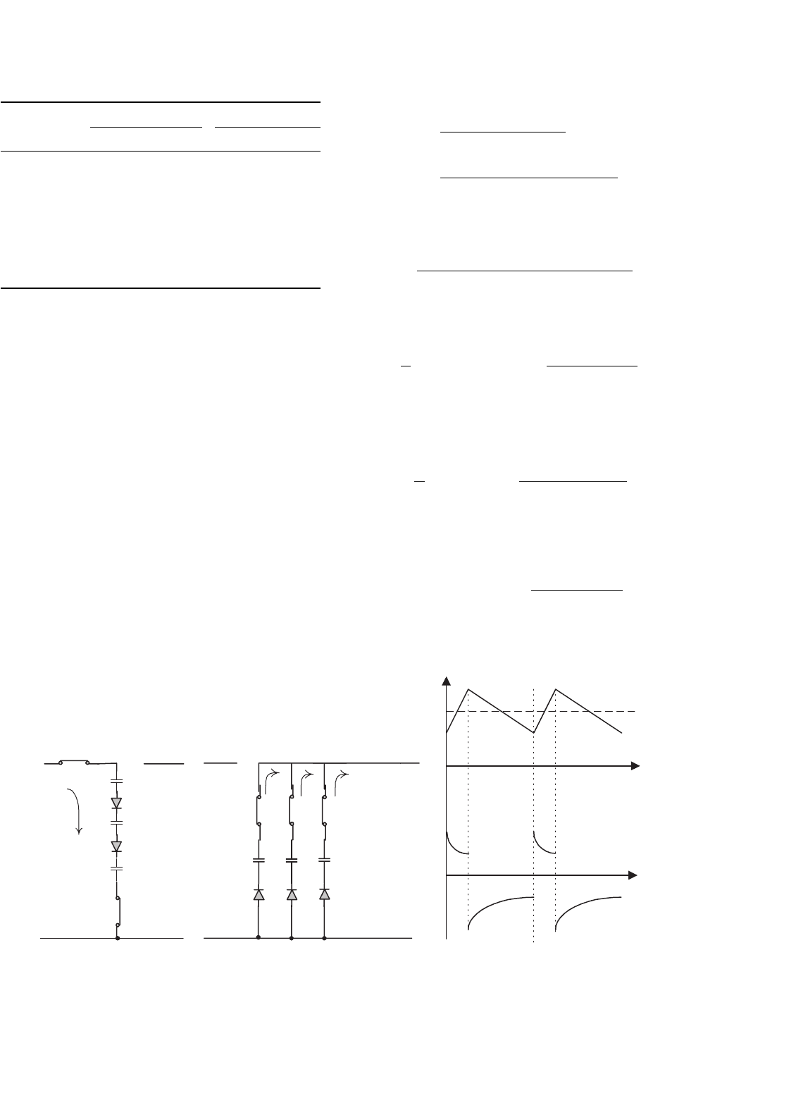
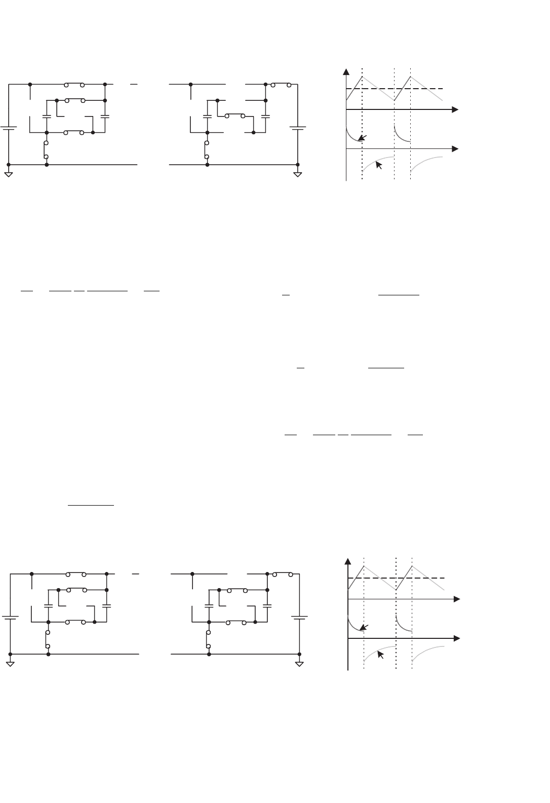
) is decreasing. Mode A implements
the current-amplification technique. The voltage and cur-
rent waveforms are shown in Fig. 14.76c. All three capacitors
are charged in series during state-on. The input current flows
through three capacitors and the charges accumulated on the
three capacitors should be the same. These three capacitors are
discharged in parallel during state-off. Therefore, the output
current is amplified by three times.
+
−
V
H
C
1
+
−
S
1
, S
10
, D
5
, D
6
On
+
−
V
L
C
2
+
−
S
2
, S
3
, S
4
, D
8
,D
9
, D
10
On
(a)
+
−
V
L
(b)
+
−
V
H
(c)
S
1
S
10
D
9
S
2
i
C1
i
C3
kT
T
V
C1
kT T
t
t
i
C1
v
C1
C
3
+
−
D
10
C
1
D
8
+
−
S
3
S
4
i
C2
i
C1
C
2
C
3
+
−
+
−
D
5
D
6
FIGURE 14.76 Mode A operation: (a) state-on; (b) state-off; and (c) voltage and current waveforms.
The variation of the voltage across capacitor C
1
is:
v
C1
=
k(V
H
−3V
C1
−2V
D
)
fCR
AN
=
2.4k(1 − k)(V
H
−3V
L
−5V
D
)
(2.4 +0.6k)fCR
AN
(14.237)
After calculation,
V
C1
=
k(V
H
−2V
D
) +2.4(1 −k)(V
L
+V
D
)
2.4 +0.6k
(14.238)
The average output current is
I
L
=
3
T
T
kT
i
C1
(t)dt ≈ 3(1 − k)
V
C1
−V
L
−V
D
R
AF
(14.239)
The average input current is
I
H
=
1
T
kT
0
i
C1
(t)dt ≈ k
V
H
−3V
C1
−2V
D
R
AN
(14.240)
Therefore, we have 3I
H
= I
L
.
Output power is
P
O
= V
L
I
L
= 3(1 −k)V
L
V
C1
−V
L
−V
D
R
AF
(14.241)
14 DC/DC Conversion Technique and 12 Series Luo-converters 309
Input power
P
I
= V
H
I
H
= kV
H
V
H
−3V
C1
−V
D
R
AN
(14.242)
The transfer efficiency is
η
A
=
P
O
P
I
=
1 −k
k
3V
L
V
H
V
C1
−V
L
−V
D
V
H
−3V
C1
−V
D
R
AN
R
AF
=
3V
L
V
H
(14.243)
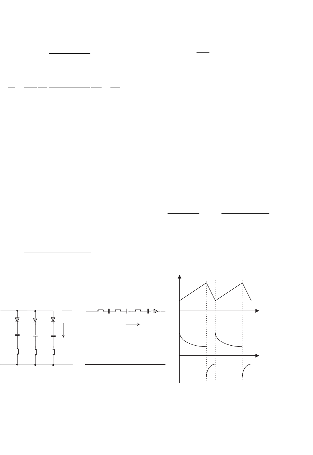
For Mode B, state-on is shown in Fig. 14.77a: switches S
8
,
S
9
, and S
10
are closed and diodes D
2
,D
3
, and D
4
are con-
ducted. Other switches and diodes are off. In this case all three
capacitors are charged via each circuit V
L
–D
2
(and D
3
,D
4
)–
C
1
(and C
2
, C
3
)–S
8
(and S
9
,S
10
), and the voltage across three
capacitors are increasing. The equivalent circuit resistance is
R
BN
= r
S
+ r
C
and the voltage deduction is V
D
in each cir-
cuit. State-off is shown in Fig. 14.77b: switches S
5
,S
6
, and S
7
are closed and diode D
1
is on. Other switches and diodes are
open. In this case all capacitors is discharged via the circuit
V
L
–S
7
–C
3
–S
6
–C
2
–S
5
–C
1
–D
1
–V
H
, and the voltage across all
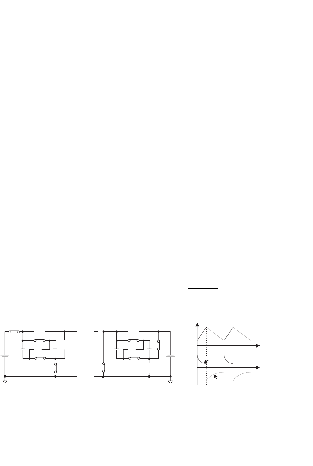
capacitors is decreasing. Mode B implements the voltage-lift
technique. The voltage and current waveforms are shown in
Fig. 14.77c. All three capacitors are charged in parallel during
state-on. The input voltage is applied to the three capacitors
symmetrically, so that the voltages across these three capacitors
should be same. They are discharged in series during state-off.
Therefore, the output voltage is lifted by three times.
The variation of the voltage across capacitor C is:
v
C1
=
k(1 − k)[4(V
L
−V
D
) −V
H
]
fCR
BN
(14.244)
S
8
, S
9
, S
10
, D
2
, D
3
, D
4
On
(c)
kT T
V
C1
kT T
t
t
i
C1
ν
C1
−
V
L
S
7
, S
6
, S
5
, D
1
On
+
−
V
H
+
(b)
S
7
S
6
S
5
C
2
C
3
C
1
D
1
i
C1
−
+
−
V
L
+
−
V
H
+
(a)
S
10
C
1
S
9
C
2
+
+
−
−
C
3
D
4
D
3
D
2
S
8
i
C1
FIGURE 14.77 Mode B operation: (a) state-on; (b) state-off; and (c) voltage and current waveforms.
After calculation
V
C1
= k(V
L
−V
D
) +
1 −k
3
(V
H
−V
L
+V
D
) (14.245)
The average input current is
I
L
=
1
T
3
kT
0
i
C1
(t)dt +
T
kT
i
C1
(t)dt
≈ 3k
V
L
−V
C1
−V
D
R
BN
+(1 −k)
3V
C1
+V
L
−V
H
−V
D
R
BF
(14.246)
The average output current is
I
H
=
1
T
T
kT
i
C1
(t)dt ≈ (1 − k)
3V
C1
+V
L
−V
H
−V
D
R
BF
(14.247)
From this formula, we have 4I
H
= I
L
.
Input power is
P
I
=V
L
I
L
=V
L
3k
V
L
−V
C
−V
D
R
BN
+(1−k)
3V
C
+V
L
−V
H
−V
D
R
BF
(14.248)
Output power is
P
O
= V
H
I
H
= V
H
(1 −k)
3V
C
+V
L
−V
H
−V
D
R
BF
(14.249)
310 F. L. Luo and H. Ye
The efficiency is
η
B
=
P
O
P
I
=
V
H
4V
L
(14.250)
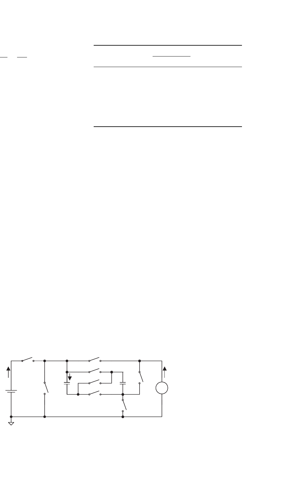
14.8.2 Four-quadrant Switched-capacitor
DC/DC Luo-converter
Four-quadrant switched-capacitor DC/DC Luo-converter is
shown in Fig. 14.78. Since it performs the voltage-lift technique,
it has a simple structure with four-quadrant operation. This
converter consists of eight switches and two capacitors. The
source voltage V
1
and load voltage V
2
(e.g. a battery or DC
motor back EMF) are usually constant voltages. In this paper
they are supposed to be ±21 V and ±14 V. Capacitors C
1
and
C
2
are same and C
1
= C
2
= 2000 µF. The circuit equivalent
resistance R = 50 m. Therefore, there are four modes of
operation for this converter:
1. Mode A: energy is converted from source to positive
voltage load; the first-quadrant operation, Q
I
;
2. Mode B: energy is converted from positive voltage load
to source; the second-quadrant operation, Q
II
;
3. Mode C: energy is converted from source to negative
voltage load; the third-quadrant operation, Q
III
;
4. Mode D: energy is converted from negative voltage
load to source; the fourth-quadrant operation, Q
IV
.
The first-quadrant (Mode A) is so called the forward motor-
ing (Forw. Mot.) operation. V
1
and V
2
are positive, and
I
1
and I
2
are positive as well. The second-quadrant (Mode
B) is so called the forward regenerative (Forw. Reg.) braking
operation. V
1
and V
2
are positive, and I
1
and I
2
are negative.
The third-quadrant (Mode C) is so-called the reverse motor-
ing (Rev. Mot.) operation. V
1
and I
1
are positive, and V
2
and
I
2
are negative. The fourth-quadrant (Mode D) is so-called the
reverse regenerative (Rev. Reg.) braking operation. V
1
and I
2
are positive, and I
1
and V
2
are negative.
Each mode has two conditions: V
1
> V
2
and V
1
< V
2
(or
|V
2
|for Q
III
and Q
IV
). Each condition has two states: “on” and
S
1
S
3
S
2
S
5
S4
V
2
V
1
i
1
i
2
C
1
C
2
S
6
S
7
S
8
i
C1
+
+
V
C1
−
−
+
_
FIGURE 14.78 Four-quadrant sc DC/DC Luo-converter.
TABLE 14.6 Switch’s status (mentioned switches are not open)
Quadrant No.
and mode
Condition State Source side Load side
ON OFF
QI, Mode A V
1
> V
2
S
1,4,6,8
S
2,4,6,8
V
1
+ V
2
+
Forw. Mot. V
1
< V
2
S
1,4,6,8
S
2,4,7
I
1
+ I
2
+
QII, Mode B V
1
> V
2
S
2,4,6,8
S
1,4,7
V
1
+ V
2
+
Forw. Reg. V
1
< V
2
S
2,4,6,8
S
1,4,6,8
I
1
− I
2
−
QIII, Mode C V
1
> |V
2
| S
1,4,6,8
S
3,5,6,8
V
1
+ V
2
−
Rev. Mot. V
1
< |V
2
| S
1,4,6,8
S
3,5,7
I
1
+ I
2
−
QIV Mode D V
1
> |V
2
| S
3,5,6,8
S
1,4,7
V
1
+ V
2
−
Rev. Reg. V
1
< |V
2
| S
3,5,6,8
S
1,4,6,8
I
1
− I
2
+
“off.” Usually, each state is operating in various conduction
duty k for different currents. As usual, the efficiency of all SC
DC/DC converters is independent from the conduction duty
cycle k. The switching period is T where T = 1/f . The switch
status is shown in Table 14.6.
As usual, the transfer efficiency only relies on the ratio of
the source and load voltages, and it is independent on R, C, f,
and k. We select k = 0.5 for our description. Other values for
the reference are f = 5 kHz, V
1
= 21 V, V
2
= 14 V, and total
C = 4000 µF, R = 50 m.
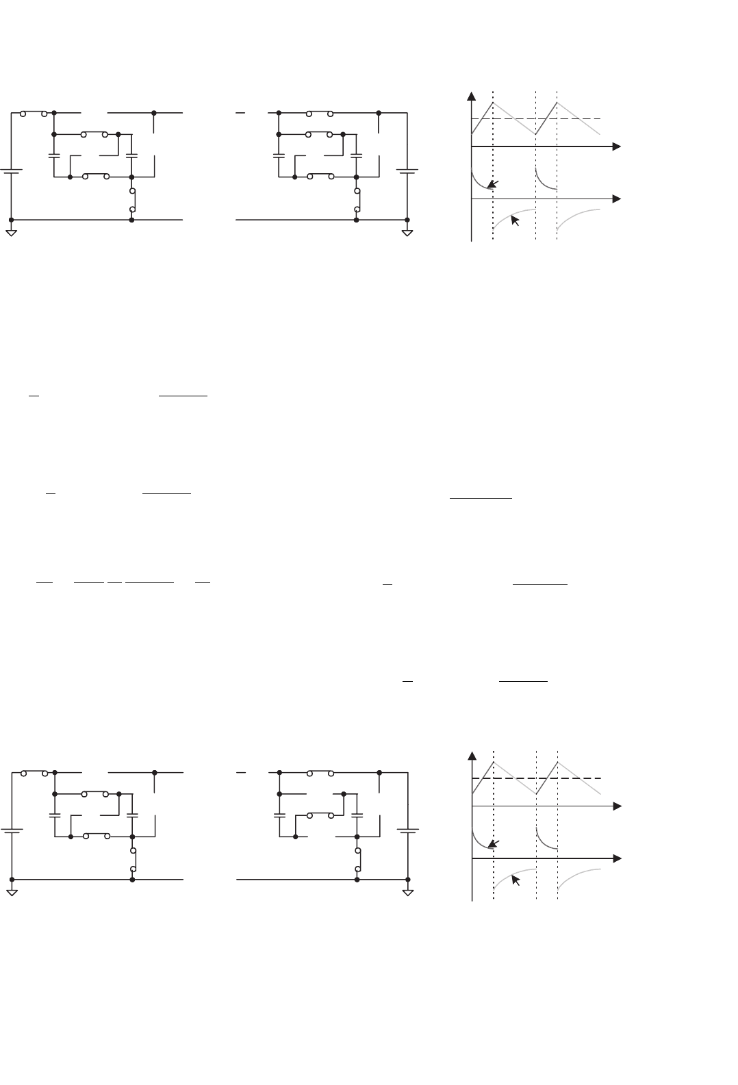
For Mode A1, condition V
1
> V
2
is shown in Fig. 14.78a.
Since V
1
> V
2
, two capacitors C
1
and C
2
are connected in
parallel. During switch-on state, switches S
1
,S
4
,S
6
, and S
8
are closed and other switches are open. In this case, capaci-
tors C
1
// C
2
are charged via the circuit V
1
–S
1
–C
1
// C
2
–S
4
, and
the voltage across capacitors C
1
and C
2
is increasing. During
switch-off state, switch S
2
,S
4
,S
6
, and S
8
are closed and other
switches are open. In this case capacitors C
1
// C
2
are discharged
via the circuit S
2
–V
2
–S
4
–C
1
// C
2
, and the voltage across capac-
itors C
1
and C
2
is decreasing. Capacitors C
1
and C
2
transfer
the energy from the source to the load.
The average capacitor voltage
V
C
= kV
1
+(1 −k)V
2
(14.251)
14 DC/DC Conversion Technique and 12 Series Luo-converters 311
S
1
S
2
S
5
S
4
V
1
C
1
C
2
S
6
S
7
S
8
+
V
C1
−
+
−
V
2
+
−
S
1
S
2
S
5
S
4
C
1
C
2
S
6
S
7
S
8
+
V
C1
−
+
−
V
2
V
1
+
−
kT
T
TkT
i
C1
v
C1
V
C1
i
1
i
2
(i) (ii) (iii)
FIGURE 14.78a Mode A1 (QI): forward motoring with V
1
> V
2
: (i) switch on: S
1
,S
4
,S
6
, and S
8
on; (ii) switch off: S
2
,S
4
,S
6
, and S
8
, on; and
(iii) waveforms.
The average current is
I
2
=
1
T
T
kT
i
C
(t)dt ≈ (1 − k)
V
C
−V
2
R
(14.252)
and
I
1
=
1
T
kT
0
i
C
(t)dt ≈ k
V
1
−V
C
R
(14.253)
The transfer efficiency is
η
A1
=
P
O
P
I
=
1 −k
k
V
2
V
1
V
C
−V
2
V
1
−V
C
=
V
2
V
1
(14.254)
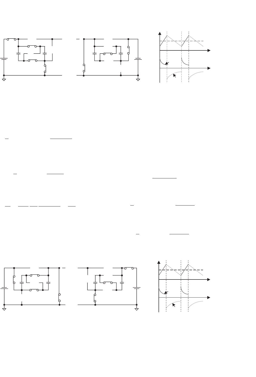
For Mode A2, condition V
1
< V
2
is shown in Fig. 14.78b.
Since V
1
< V
2
, two capacitors C
1
and C
2
are connected in
parallel during switch on and in series during switch off. This
is so-called the voltage-lift technique. During switch-on state,
switches S
1
,S
4
,S
6
, and S
8
are closed and other switches are
open. In this case, capacitors C
1
// C
2
are charged via the circuit
S
1
S
2
S
5
S
4
V
1
C
1
C
2
S
6
S
7
S
8
+
V
C1
−
+
−
V
2
+
−
S
1
S
2
S
5
S
4
C
1
C
2
S
6
S
7
S
8
+
V
C1
−
+
−
V
2
V
1
+
−
kT
T
TkT
i
C1
v
C1
V
C1
i
1
i
2
(i) (ii) (iii)
FIGURE 14.78b Mode A2 (QI): forward motoring with V
1
< V
2
: (i) switch on: S
1
,S
4
,S
6
, and S
8
, on; (ii) switch off: S
2
,S
4
, and S
7
, on; and
(iii) waveforms.
V
1
–S
1
–C
1
// C
2
–S
4
, and the voltage across capacitors C
1
and C
2
is increasing. During switch-off state, switches S
2
,S
4
, and S
7
are closed and other switches are open. In this case, capacitors
C
1
and C
2
are discharged via the circuit S
2
–V
2
–S
4
–C
1
–S
7
–C
2
,
and the voltage across capacitor C
1
and C
2
is decreasing.
Capacitors C
1
and C
2
transfer the energy from the source to
the load.
The average capacitor voltage is
V
C
=
0.5V
1
+V
2
2.5
= 11.2 (14.255)
The average current is
I
2
=
1
T
T
kT
i
C
(t)dt ≈ (1 − k)
2V
C
−V
2
R
(14.256)
and
I
1
=
1
T
kT
0
i
C
(t)dt ≈ k
V
1
−V
C
R
(14.257)
312 F. L. Luo and H. Ye
V
1
+
−
S
1
S
1
S
2
S
2
S
5
S
5
S
4
S
4
C
1
C
1
C
2
C
2
S
6
S
6
S
7
S
7
S
8
S
8
+
V
C1
−
+
V
C1
−
+
−
V
2
V
2
V
1
+
−
+
−
kT
T
TkT
i
C1
v
C1
V
C1
i
1
i
2
(i) (ii) (iii)
FIGURE 14.78c Mode B1 (QII): forward regenerative braking with V
1
> V
2
: (i) switch on: S
2
,S
4
,S
6
, and S
8
, on; (ii) switch off; S
1
,S
4
(S
5
), and S
7
on; and (iii) waveforms.
The transfer efficiency is
η
A2
=
P
O
P
I
=
1 −k
k
V
2
V
1
2V
C
−V
2
V
1
−V
C
=
V
2
2V
1
(14.258)
For Mode B1, condition V
1
> V
2
is shown in Fig. 14.78c.
Since V
1
> V
2
, two capacitors C
1
and C
2
are connected
in parallel during switch on and in series during switch off.
The voltage-lift technique is applied. During switch-on state,
switches S
2
,S
4
,S
6
, and S
8
are closed. In this case, capaci-
tors C
1
// C
2
are charged via the circuit V
2
–S
2
–C
1
// C
2
–S
4
, and
the voltage across capacitors C
1
and C
2
is increasing. During
switch-off state, switches S
1
,S
4
, and S
7
are closed. In this case,
capacitors C
1
and C
2
are discharged via the circuit S
1
–V
1
–
S
4
–C
2
–S
7
–C
1
, and the voltage across capacitor C
1
and C
2
is
decreasing. Capacitors C
1
and C
2
transfer the energy from the
load to the source. Therefore, we have I
2
= 2I
1
.
The average capacitor voltage is
V
C
=
0.5V
2
+V
1
2.5
= 11.2 (14.259)
S
1
S
2
S
5
S
4
C
1
C
2
S
6
S
7
S
8
+
V
C1
−
+
−
V
2
V
1
+
−
V
1
+
−
S
1
S
2
S
5
S
4
C
1
C
2
S
6
S
7
S
8
+
V
C1
−
V
2
+
−
kT
T
TkT
i
C1
v
C1
V
C1
i
1
i
2
(i) (ii) (iii)
FIGURE 14.78d Mode B2 (QII): forward regenerative braking with V
1
< V
2
: (i) switch on: S
2
,S
4
,S
6
, and S
8
, on; (ii) switch off: S
1
,S
4
(S
5
), S
6
, and
S
8
on; and (iii) waveforms.
The average current is
I
1
=
1
T
T
kT
i
C
(t)dt ≈ (1 − k)
2V
C
−V
1
R
(14.260)
and
I
2
=
1
T
kT
0
i
C
(t)dt ≈ k
V
2
−V
C
R
(14.261)
The transfer efficiency is
η
B1
=
P
O
P
I
=
1 −k
k
V
1
V
2
2V
C
−V
1
V
2
−V
C
=
V
1
2V
2
(14.262)
For Mode B2, condition V
1
< V
2
is shown in Fig. 14.78d.
Since V
1
< V
2
, two capacitors C
1
and C
2
are connected in
parallel. During switch-on state, switches S
2
,S
4
,S
6
, and S
8
are
closed. In this case, capacitors C
1
// C
2
are charged via the circuit
V
2
–S
2
–C
1
// C
2
–S
4
, and the voltage across capacitors C
1
and C
2
14 DC/DC Conversion Technique and 12 Series Luo-converters 313
is increasing. During switch-off state, switches S
1
,S
4
,S
6
, and
S
8
are closed. In this case capacitors C
1
// C
2
is discharged via the
circuit S
1
–V
1
–S
4
–C
1
// C
2
, and the voltage across capacitors C
1
and C
2
is decreasing. Capacitors C
1
and C
2
transfer the energy
from the load to the source. Therefore, we have I
2
= I
1
.
The average capacitor voltage is
V
C
= kV
2
+(1 −k)V
1
(14.263)
The average current is
I
1
=
1
T
T
kT
i
C
(t)dt ≈ (1 − k)
V
C
−V
1
R
(14.264)
and
I
2
=
1
T
kT
0
i
C
(t)dt ≈ k
V
2
−V
C
R
(14.265)
The transfer efficiency is
η
B2
=
P
O
P
I
=
1 −k
k
V
1
V
2
V
C
−V
1
V
2
−V
C
=
V
1
V
2
(14.266)
For Mode C1, condition V
1
> |V
2
| is shown in Fig. 14.78e.
Since V
1
> |V
2
|, two capacitors C
1
and C
2
are connected in
parallel. During switch-on state, switches S
1
,S
4
,S
6
, and S
8
are closed. In this case, capacitors C
1
// C
2
are charged via the
circuit V
1
–S
1
–C
1
// C
2
–S
4
, and the voltage across capacitors C
1
and C
2
is increasing. During switch-off state, switches S
3
,S
5
,
S
6
, and S
8
are closed. Capacitors C
1
and C
2
are discharged via
the circuit S
3
–V
2
–S
5
–C
1
// C
2
, and the voltage across capacitors
C
1
and C
2
is decreasing. Capacitors C
1
and C
2
transfer the
energy from the source to the load. We have I
1
= I
2
.
S
1
S
1
S
2
S
2
S
5
S
5
S
4
S
4
S
3
V
1
V
1
C
1
C
1
C
2
C
2
S
6
S
6
S
7
S
7
S
8
S
8
++
V
C1
V
C1
−−
+
−
V
2
V
2
+
−
+
−
+
−
kT T
TkT
i
C1
v
C1
V
C1
i
1
i
2
(i) (ii) (iii)
FIGURE 14.78e Mode C1 (QIII): reverse motoring with V
1
> |V
2
|: (i) switch on: S
1
,S
4
,S
6
, and S
8
on; (ii) switch off: S
3
,S
5
,S
6
, and S
8
on; and
(iii) waveforms.
The average capacitor voltage is
V
C
= kV
1
+(1 −k)|V
2
| (14.267)
The average current (absolute value) is
I
2
=
1
T
T
kT
i
C
(t)dt ≈ (1 − k)
V
C
−|V
2
|
R
(14.268)
and the average input current is
I
1
=
1
T
kT
0
i
C
(t)dt ≈ k
V
1
−V
C
R
(14.269)
The transfer efficiency is
η
C1
=
P
O
P
I
=
1 −k
k
|V
2
|
V
1
V
C
−|V
2
|
V
1
−V
C
=
|V
2
|
V
1
(14.270)
For Mode C2, condition V
1
< |V
2
| is shown in Fig. 14.78f.
Since V
1
< |V
2
|, two capacitors C
1
and C
2
are connected in
parallel during switch on and in series during switch off, apply-
ing the voltage-lift technique. During switch-on state, switches
S
1
,S
4
,S
6
, and S
8
, are closed. Capacitors C
1
and C
2
are charged
via the circuit V
1
–S
1
–C
1
// C
2
–S
4
, and the voltage across capac-
itors C
1
and C
2
is increasing. During switch-off state, switches
S
3
,S
5
, and S
7
are closed. Capacitors C
1
and C
2
is discharged via
the circuit S
3
–V
2
–S
5
–C
1
–S
7
–C
2
, and the voltage across capac-
itor C
1
and C
2
is decreasing. Capacitors C
1
and C
2
transfer the
energy from the source to the load. We have I
1
= 2I
2
.
The average capacitor voltage is
V
C
=
0.5V
1
+|V
2
|
2.5
= 11.2 (14.271)
314 F. L. Luo and H. Ye
S
1
S
1
S
2
S
2
S
5
S
4
S
4
S
5
S
3
V
1
V
1
C
1
C
1
C
2
C
2
S
6
S
6
S
7
S
7
S
8
S
8
+
V
C1
−
+
V
C1
−
+
−
+
−
V
2
V
2
+
−
+
−
kT T
TkT
i
C1
v
C1
V
C1
i
1
i
2
(i) (ii) (iii)
FIGURE 14.78f Mode C2 (QIII): reverse motoring with V
1
< |V
2
|: (i) switch on: S
1
,S
4
,S
6
, and S
8
, on; (ii) switch off: S
3
,S
5
, and S
7
, on; and
(iii) waveforms.
The average currents are
I
2
=
1
T
T
kT
i
C
(t)dt ≈ (1 − k)
2V
C
−|V
2
|
R
(14.272)
and
I
1
=
1
T
kT
0
i
C
(t)dt ≈ k
V
1
−V
C
R
(14.273)
The transfer efficiency is
η
C2
=
P
O
P
I
=
1 −k
k
|V
2
|
V
1
2V
C
−|V
2
|
V
1
−V
C
=
|V
2
|
2V
1
(14.274)
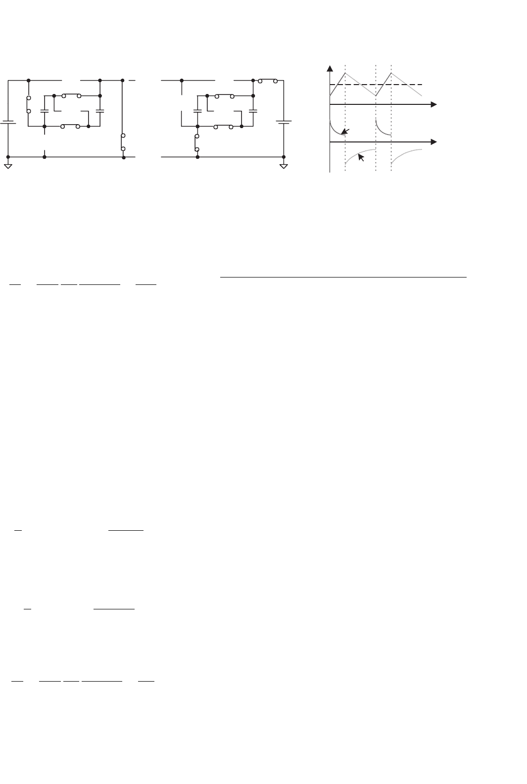
For Mode D1, condition V
1
> |V
2
| is shown in Fig. 14.78g.
Since V
1
> |V
2
|, two capacitors C
1
and C
2
are connected in
parallel during switch on and in series during switch off, apply-
ing the voltage-lift technique. During switch-on state, switches
S
1
S
1
S
2
S
5
S
4
S
3
C
1
C
2
S
6
S
7
S
8
+
V
C1
−
S
2
S
5
S
4
C
1
C
2
S
6
S
7
S
8
+
V
C1
−
+
+
−
−
V
2
V
2
V
1
V
1
+
+
−
−
kT T
TkT
i
C1
v
C1
V
C1
i
1
i
2
(i) (ii) (iii)
FIGURE 14.78g Mode D1 (QIV): reverse regenerative braking with V
1
> |V
2
|: (i) switch on: S
3
,S
4
,S
6
, and S
8
, on; (ii) switch off: S
1
,S
4
, and S
7
on; and (iii) waveforms.
S
3
,S
5
,S
6
, and S
8
are closed. In this case, capacitors C
1
// C
2
are charged via the circuit V
2
–S
3
–C
1
// C
2
–S
5
, and the voltage
across capacitors C
1
and C
2
is increasing. During switch-off
state, switches S
1
,S
4
, and S
7
are closed. Capacitors C
1
and
C
2
are discharged via the circuit S
1
–V
1
–S
4
–C
2
–S
7
–C
1
, and the
voltage across capacitor C
1
and C
2
is decreasing. Capacitors
C
1
and C
2
transfer the energy from the load to the source. We
have I
2
= 2I
1
.
The average capacitor voltage is
V
C
=
0.5|V
2
|+V
1
2.5
= 11.2 (14.275)
The average currents are
I
1
=
1
T
T
kT
i
C
(t)dt ≈ (1 − k)
2V
C
−V
1
R
(14.276)
and
I
2
=
1
T
kT
0
i
C
(t)dt ≈ k
|V
2
|−V
C
R
(14.277)
14 DC/DC Conversion Technique and 12 Series Luo-converters 315
S
1
S
2
S
5
S
4
S
3
C
1
C
2
S
6
S
7
S
8
+
V
C1
−
+
−
V
2
V
1
+
−
S
1
S
2
S
5
S
4
C
1
C
2
S
6
S
7
S
8
+
V
C1
−
+
−
V
2
V
1
+
−
kT T
TkT
i
C1
v
C1
V
C1
i
1
i
2
(i) (ii) (iii)
FIGURE 14.78h Mode D2 (QIV): reverse regenerative braking with V
1
< |V
2
|: (i) switch on: S
3
,S
5
,S
6
, and S
8
, on; (ii) switch off: S
1
,S
4
,S
6
, and
S
8
on; and (iii) waveforms.
The transfer efficiency is
η
D1
=
P
O
P
I
=
1 −k
k
V
1
|V
2
|
2V
C
−V
1
|V
2
|−V
C
=
V
1
2|V
2
|
(14.278)
For Mode D2, condition V
1
< |V
2
| is shown in Fig. 14.78h.
Since V
1
< |V
2
|, two capacitors C
1
and C
2
are connected in
parallel. During switch-on state, switches S
3
,S
5
,S
6
, and S
8
are closed. In this case, capacitors C
1
// C
2
are charged via the
circuit V
2
–S
3
–C
1
// C
2
–S
5
, and the voltage across capacitors C
1
and C
2
is increasing. During switch-off state, switches S
1
,S
4
,
S
6
, and S
8
are closed. Capacitors C
1
and C
2
are discharged via
the circuit S
1
–V
1
–S
4
–C
1
// C
2
, and the voltage across capacitors
C
1
and C
2
is decreasing. Capacitors C
1
and C
2
transfer the
energy from the load to the source. We have I
2
= I
1
.
The average capacitor voltage is
V
C
= k|V
2
|+(1 −k)V
1
(14.279)
The average currents are
I
1
=
1
T
T
kT
i
C
(t)dt ≈ (1 − k)
V
C
−V
1
R
(14.280)
and
I
2
=
1
T
kT
0
i
C
(t)dt ≈ k
|V
2
|−V
C
R
(14.281)
The transfer efficiency is
η
D2
=
P
O
P
I
=
1 −k
k
V
1
|V
2
|
V
C
−V
1
|V
2
|−V
C
=
V
1
|V
2
|
(14.282)
14.9 Multiple-lift Push–Pull
Switched-capacitor Luo-converters
Micro-power-consumption technique requires high power
density DC/DC converters and power supply source. Voltage-
lift (VL) technique is a popular method to apply in electronic
circuit design. Since switched-capacitor can be integrated
into power integrated circuit (IC) chip, its size is small.
Combining switched-capacitor and VL techniques the DC/DC
converters with small size, high power density, high voltage
transfer gain, high power efficiency, and low EMI can be
constructed. This section introduces a new series DC/DC con-
verters – multiple-lift push–pull switched-capacitor DC/DC
Luo-converters. There are two subseries:
• P/O multiple-lift (ML) push–pull (PP) switched-
capacitor (SC) DC/DC Luo-converter;
• N/O multiple-lift push–pull switched-capacitor DC/DC
Luo-converter.
14.9.1 P/O Multiple-lift Push–Pull
Switched-capacitor DC/DC
Luo-converter
P/O ML-PP SC DC/DC Luo-converters have several subseries:
• Main series;
• Additional series;
• Enhanced series;
• Re-enhanced series;
• Multiple-enhanced series.
We only introduce three circuits of main series and addi-
tional series in this section.
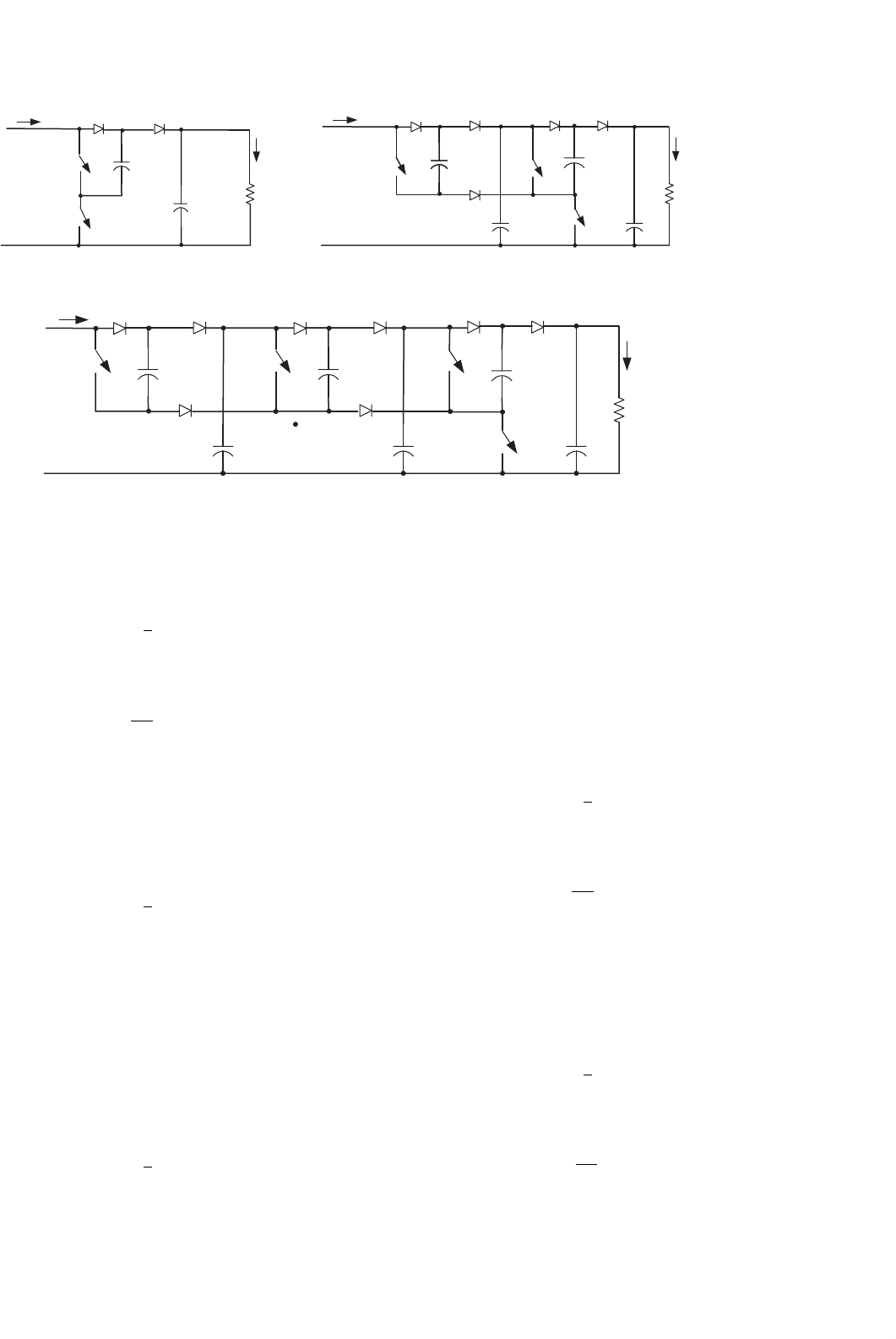
P/O ML-PP SC Luo-converter elementary circuit is shown
in Fig. 14.79a. Its output voltage and current are
V
O
= 2V
I
316 F. L. Luo and H. Ye
C
1
C
2
V
C2
V
C1
D
1
D
1
S
1
S
1
+
−
C
1
V
C1
+
−
+
−
R
V
in
+
−
V
in
+
−
V
O
+
−
I
in
I
in
I
O
D
2
D
2
S
S
C
1
C
2
V
C2
V
C1
D
1
+
−
+
−
C
2
V
C2
+
−
R
R
V
in
+
−
V
O
+
−
V
O
+
−
I
in
I
O
I
O
D
2
C
3
C
3
V
C3
D
3
D
3
+
_
V
C3
+
_
C
5
V
C5
+
_
C
4
V
C4
+
_
D
4
D
4
D
5
D
7
D
6
D
8
C
4
C
6
V
C4
+
−
V
C6
+
−
S
1
V
1
V
1
V
2
S
S
2
S
2
S
3
D
5
(a) (b)
(c)
FIGURE 14.79 P/O ML-PP SC Luo-converter: (a) elemental; (b) re-lift; and (c) triple-lift circuits.
and
I
O
=
1
2
I
I
The voltage transfer gain is
M
E
=
V
O
V
I
= 2 (14.283)
P/O ML-PP SC Luo-converter re-lift circuit is shown in
Fig. 14.79b. Its output voltage and current are
V
O
= 4V
I
and
I
O
=
1
4
I
I
The voltage transfer gain is
M
R
= 4 (14.284)
P/O ML-PP SC Luo-converter triple-lift circuit is shown
in Fig. 14.79c. Its output voltage and current are
V
O
= 8V
I
and
I
O
=
1
8
I
I
The voltage transfer gain is
M
T
= 8 (14.285)
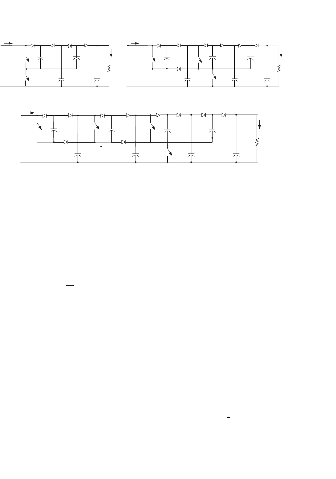
P/O ML-PP SC Luo-converter additional circuit is shown
in Fig. 14.80a. Its output voltage and current are
V
O
= 3V
I
and
I
O
=
1
3
I
I
The voltage transfer gain is
M
A
=
V
O
V
I
= 3 (14.286)
P/O ML-PP SC Luo-converter additional re-lift circuit is
shown in Fig. 14.80b. Its output voltage and current are
V
O
= 6V
I
and
I
O
=
1
6
I
I
The voltage transfer gain is
M
AR
=
V
O
V
I
= 6 (14.287)
14 DC/DC Conversion Technique and 12 Series Luo-converters 317
D
1
D
1
D
1
D
11
D
11
D
11
S
1
S
1
S
1
C
1
V
C1
+
−
C
1
V
C1
+
−
C
1
V
C1
+
−
C
11
V
C11
+
−
C
11
V
C11
+
−
C
11
V
C11
+
−
C
12
V
C12
+
−
C
12
V
C12
+
−
C
12
V
C12
+
−
C
2
V
C2
+
−
C
2
V
C2
+
−
C
2
V
C2
+
−
C
4
V
C4
+
−
C
4
V
C4
+
−
R
R
R
V
in
+
−
V
in
+
−
V
in
+
−
I
in
I
in
I
in
V
O
+
−
V
O
+
−
V
O
+
−
I
O
I
O
I
O
D
2
D
2
D
2
D
12
D
12
D
12
S
D
3
D
3
C
3
V
C3
+
_
C
3
V
C3
+
_
C
5
V
C5
+
_
D
4
D
4
D
5
D
5
D
7
D
6
D
8
C
6
V
C6
+
−
V
1
V
1
V
1
V
2
V
2
S
2
S
2
S
3
(a) (b)
(c)
S
S
FIGURE 14.80 P/O ML-PP SC Luo-converter re-lift circuit: (a) additional; (b) re-lift; and (c) triple-lift circuits.
P/O ML-PP SC Luo-converter additional triple-lift circuit
is shown in Fig. 14.80c. Its output voltage and current are
V
O
= 12V
I
and
I
O
=
1
12
I
I
The voltage transfer gain is
M
AT
=
V
O
V
I
= 12 (14.288)
14.9.2 N/O Multiple-lift Push–Pull
Switched-capacitor DC/DC
Luo-converter
N/O ML-PP SC DC/DC Luo-converters have several subseries:
• Main series;
• Additional series;
• Enhanced series;
•
Re-enhanced series;
• Multiple-enhanced series.
We only introduce three circuits of main series and addi-
tional series in this section.
N/O ML-PP SC Luo-converter elementary circuit is shown
in Fig. 14.81a. Its output voltage and current are
V
O
= V
I
and
I
O
= I
I
The voltage transfer gain is
M
E
=
V
O
V
I
= 1 (14.289)
N/O ML-PP SC Luo-converter re-lift circuit is shown in
Fig. 14.81b. Its output voltage and current are
V
O
= 3V
I
and
I
O
=
1
3
I
I
The voltage transfer gain is
M
R
= 3 (14.290)
N/O ML-PP SC Luo-converter triple-lift circuit is shown
in Fig. 14.81c. Its output voltage and current are
V
O
= 7V
I
and
I
O
=
1
7
I
I