Power electronic handbook
Подождите немного. Документ загружается.

318 F. L. Luo and H. Ye
R
R
C
1
I
in
I
in
V
in
+
−
V
in
+
−
V
C1
+
−
C
1
V
C1
+
−
V
C2
+
−
V
O
+
−
V
O
+
−
I
O
I
O
D
1
D
1
D
2
D
2
D
4
D
5
D
7
D
8
D
3
D
6
C
2
V
C2
+
−
C
2
V
C4
+
−
C
4
V
C6
+
−
C
6
V
C5
+
−
C
5
S
S
S
1
S
1
C
3
V
C3
+
−
S
2
V
1
V
2
S
3
R
C
1
I
in
V
in
+
−
V
C1
+
−
V
C2
+
−
V
O
+
−
I
O
D
1
D
2
C
2
S
S
1
(a) (b)
(c)
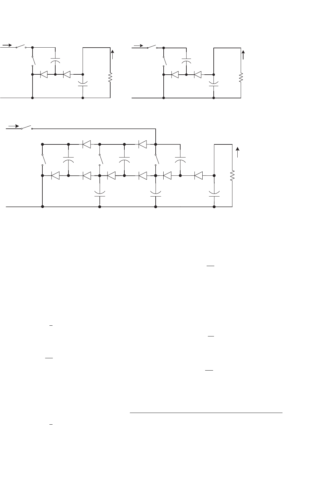
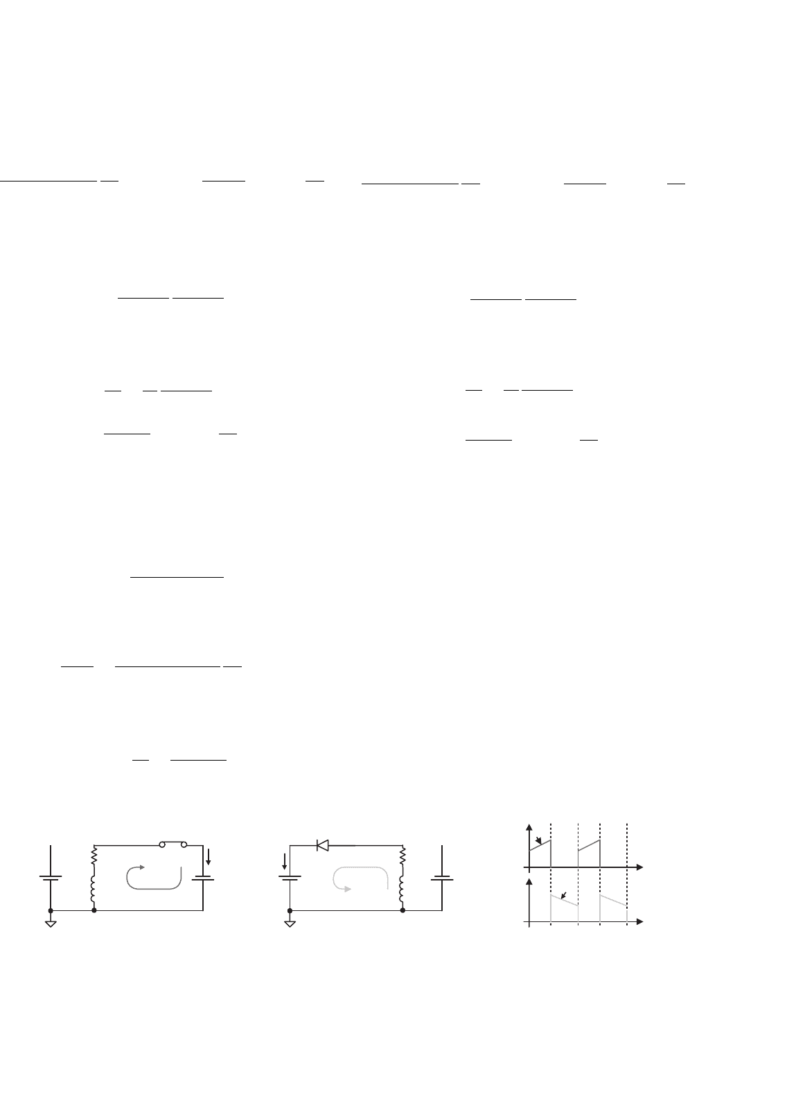
FIGURE 14.81 N/O ML-PP SC Luo-converter: (a) elemental; (b) re-lift; and (c) triple-lift circuits.
The voltage transfer gain is
M
T
= 7 (14.291)
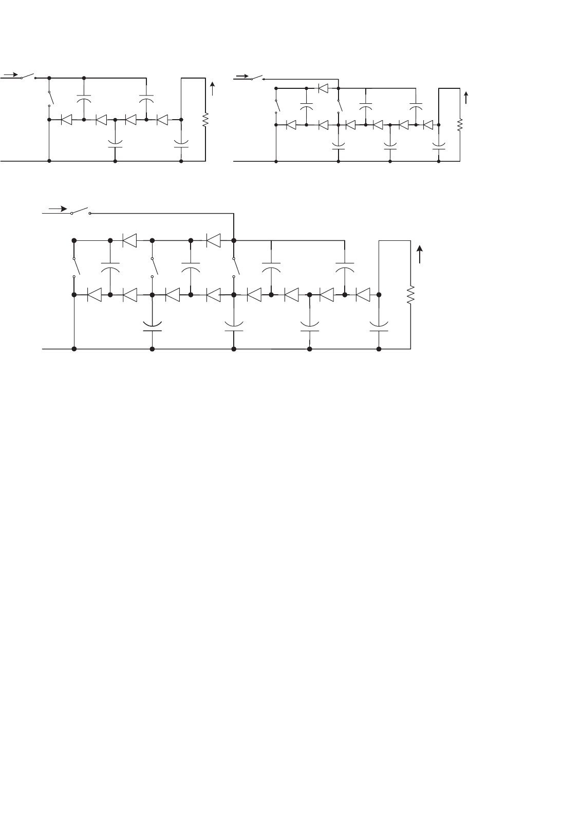
N/O ML-PP SC Luo-converter additional circuit is shown
in Fig. 14.82a. Its output voltage and current are
V
O
= 2V
I
and
I
O
=
1
2
I
I
The voltage transfer gain is
M
A
=
V
O
V
I
= 2 (14.292)
N/O ML-PP SC Luo-converter additional re-lift circuit is
shown in Fig. 14.82b. Its output voltage and current are
V
O
= 5V
I
and
I
O
=
1
5
I
I
The voltage transfer gain is
M
AR
=
V
O
V
I
= 5 (14.293)
N/O ML-PP SC Luo-converter additional triple-lift circuit
is shown in Fig. 14.82c. Its output voltage and current are
V
O
= 11V
I
and
I
O
=
1
11
I
I
The voltage transfer gain is
M
AT
=
V
O
V
I
= 11 (14.294)
14.10 Switched-inductor Multi-quadrant
Operation Luo-converters
Switched-capacitor converters usually have many switches and
capacitors, especially for the system with high ratio between
14 DC/DC Conversion Technique and 12 Series Luo-converters 319
R
R
R
I
in
V
in
+
−
C
1
V
C1
+
−
C
1
V
C1
+
−
C
1
V
C1
+
−
C
2
V
C2
+
−
C
2
V
C2
+
−
C
2
V
C2
+
−
C
4
V
C4
+
−
C
4
V
C4
+
−
C
12
C
12
V
C12
+
−
V
C12
+
−
C
12
V
C12
+
−
C
3
V
C3
+
−
C
3
V
C3
+
−
C
5
V
C5
+
−
C
6
V
C6
+
−
C
11
C
11
V
C11
+
−
V
C11
+
−
C
11
V
C11
+
−
V
O
+
−
V
O
+
−
V
O
+
−
I
O
I
O
I
O
D
1
D
1
D
1
D
2
D
2
D
2
D
4
D
4
D
5
D
5
D
7
D
8
D
3
D
3
D
6
D
11
D
11
D
11
D
12
D
12
D
12
S
S
1
S
2
S
2
S
3
I
in
I
in
V
in
+
−
V
in
+
−
S
S
S
1
S
1
V
1
V
2
V
3
(a) (b)
(c)
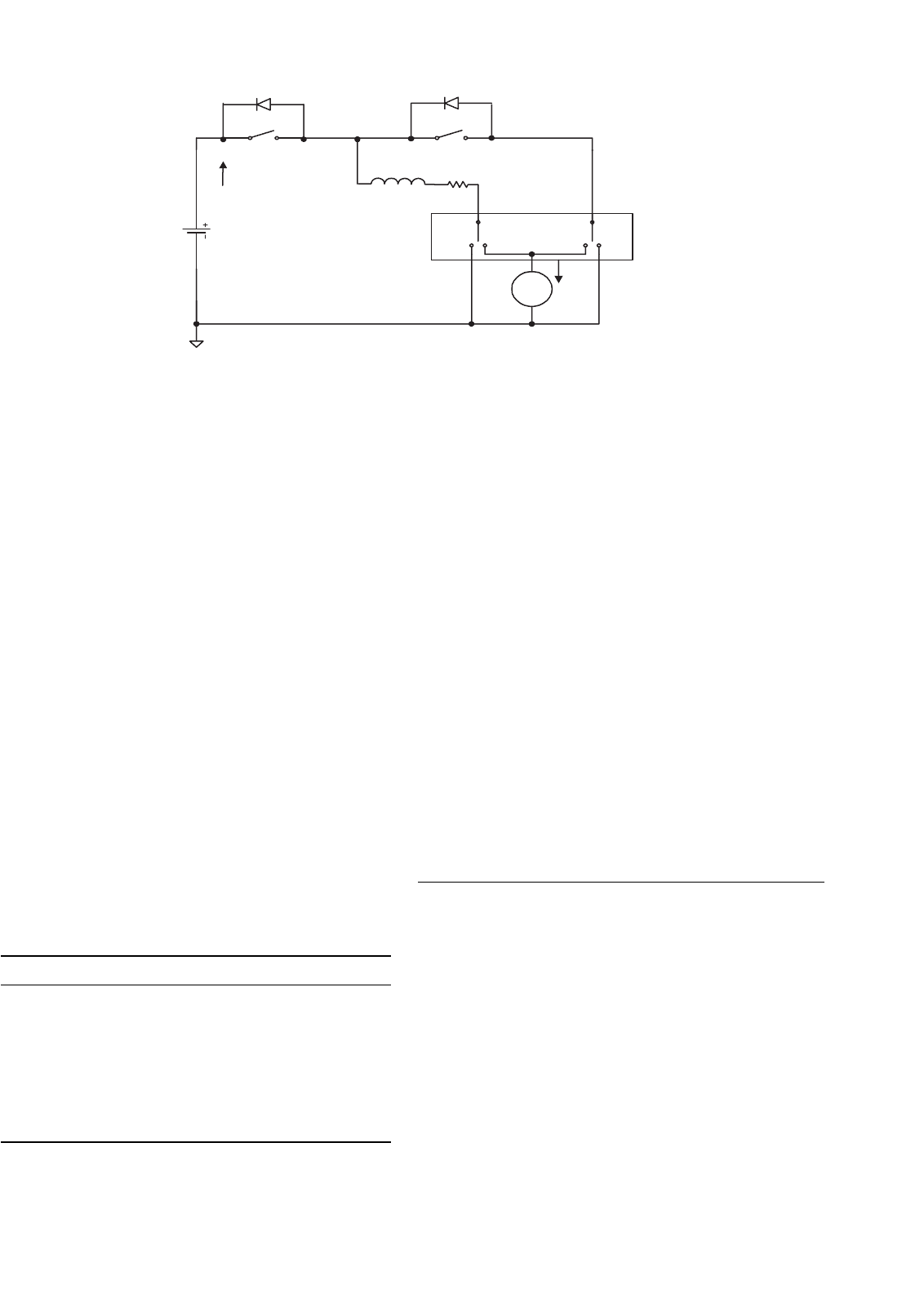
FIGURE 14.82 N/O ML-PP SC Luo-converter re-lift circuit: (a) additional; (b) re-lift; and (c) triple-lift circuits.
source and load voltages. Switched-inductor converter usually
has only one inductor even if it works in single-, two-, and/or
four-quadrant operation. Simplicity is the main advantage of
all switched inductor converters.
Switched-inductor multi-quadrant Luo-converters are the
third-generation converters, and they are made of only induc-
tor. These converters have been derived from chopper circuits.
They have three modes:
•
Two-quadrant switched-inductor DC/DC Luo-converter
in forward operation;
• Two-quadrant switched-inductor DC/DC Luo-converter
in reverse operation;
• Four-quadrant switched-inductor DC/DC Luo-converter.
The two-quadrant switched-inductor DC/DC Luo-converter
in forward operation has been derived for the energy trans-
mission of a dual-voltage system. The both, source and
load voltages are positive polarity. It performs in the first-
quadrant Q
I
and the second-quadrant Q
II
corresponding to
the DC motor forward operation in motoring and regenerative
braking states.
The two-quadrant switched-inductor DC/DC Luo-converter
in reverse operation has been derived for the energy trans-
mission of a dual-voltage system. The source voltage is
positive and load voltage is negative polarity. It performs
in the third-quadrant Q
III
and the fourth-quadrant Q
IV
corresponding to the DC motor reverse operation in motoring
and regenerative braking states.
The four-quadrant switched-inductor DC/DC Luo-converter
has been derived for the energy transmission of a dual-voltage
system. The source voltage is positive and load voltage can be
positive or negative polarity. It performs four-quadrant oper-
ation corresponding to the DC motor forward and reverse
operation in motoring and regenerative braking states.
14.10.1 Two-quadrant Switched-inductor
DC/DC Luo-converter in
Forward Operation
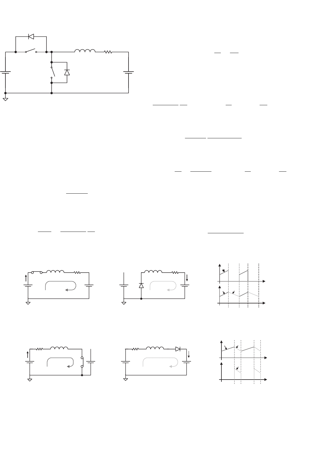
Forward operation (F) 2Q SI Luo-converter is shown in
Fig. 14.83, and it consists of two switches with two passive
diodes, two inductors, and one capacitor. The source voltage
(V
1
) and load voltage (V
2
) are usually considered as constant
voltages. The load can be a battery or motor back EMF. For
example, the source voltage is 42 V and load voltage is +14 V.
There are two modes of operation:
1. Mode A (QI): electrical energy is transferred from
source side V
1
to load side V
2
;
320 F. L. Luo and H. Ye
D
1
S
1
S
2
D
2
L
1
R
1
V
high
V
low
I
high
I
low
+
−
+
−
FIGURE 14.83 Switched-inductor QI and II DC/DC Luo-converter.
2. Mode B (QII): electrical energy is transferred from load
side V
2
to source side V
1
.
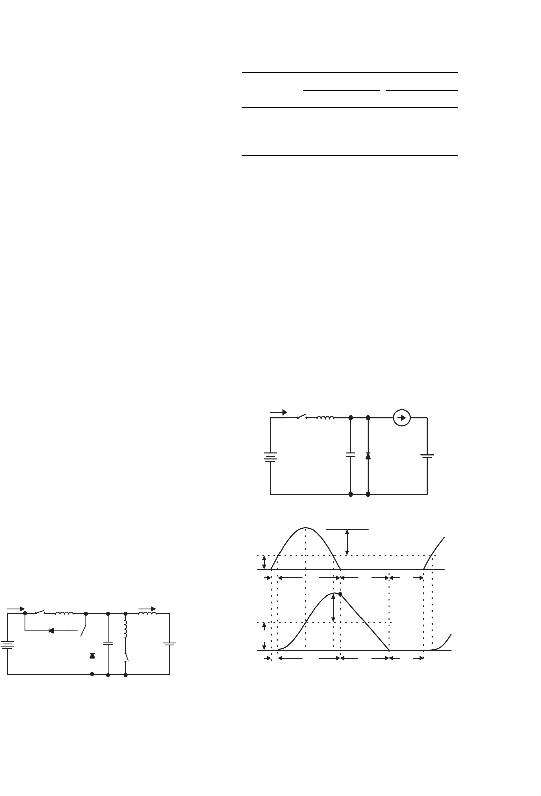
Mode A: The equivalent circuits during switch-on and -off
periods are shown in Figs. 14.84a and b. The typical output
voltage and current waveforms are shown in Fig. 14.84c.
We have the average inductor current I
L
as
I
L
=
kV
1
−V
2
R
(14.295)
The variation ratio of the inductor current i
L
is
ζ =
i
L
/2
I
L
=
k(1 − k)V
1
kV
1
−V
2
R
2fL
(14.296)
S
1
L
1
R
1
L
1
R
1
V
high
V
low
i
1
i
2
kT T
kT T
t
t
i
I
i
o
i
I
i
o
i
1
i
1
i
2
(a) (b) (c)
+
−
V
high
+
−
+
−
V
low
+
−
D
2
FIGURE 14.84 Mode A of F 2Q SI Luo-converter: (a) state-on: S
1
on; (b) state-off: D
2
on, S
1
, off; and (c) input and output current waveforms.
kT T
kT T
t
t
i
I
i
o
i
1
i
2
i
2
(a) (b) (c)
S
2
L
1
R
1
V
high
V
low
i
1
i
I
+
−
+
−
L
1
R
1
i
2
D
1
i
o
V
low
+
−
V
high
+
−
FIGURE 14.85 Mode B of F 2Q SI Luo-converter: (a) state-on: S
2
on; (b) state-off: D
1
on, S
2
off; and (c) input and output current waveforms.
The power transfer efficiency is
η
A
=
P
O
P
I
=
V
2
kV
1
(14.297)
The boundary between continuous and discontinuous
regions is defined as
ζ ≥ 1 i.e.
k(1 − k)V
1
kV
1
−V
2
R
2fL
≥ 1ork ≤
V
2
V
1
+k(1 − k)
R
2fL
(14.298)
Average inductor current I
L
in discontinuous region is
I
L
=
V
1
V
2
+RI
L
V
1
−V
2
−RI
L
2fL
k
2
(14.299)
The power transfer efficiency is
η
A−dis
=
P
O
P
I
=
V
2
V
2
+RI
L
with k ≤
V
2
V
1
+k(1 − k)
R
2fL
(14.300)
Mode B: The equivalent circuits during switch-on and -off
periods are shown in Figs. 14.85a and b. The typical output
voltage and current waveforms are shown in Fig. 14.85c.
The average inductor current I
L
is
I
L
=
V
2
−(1 −k)V
1
R
(14.301)
14 DC/DC Conversion Technique and 12 Series Luo-converters 321
The variation ratio of the inductor current i
L
is
ζ =
i
L
/2
I
L
=
k(1 − k)V
1
V
2
−(1 −k)V
1
R
2fL
(14.302)
The power transfer efficiency
η
B
=
P
O
P
I
=
(1 −k)V
1
V
2
(14.303)
The boundary between continuous and discontinuous
regions is defined as
ζ ≥ 1, i.e.
k(1−k)V
1
V
2
−(1−k)V
1
R
2fL
≥1ork ≤
1−
V
2
V
1
+k(1−k)
R
2fL
(14.304)
Average inductor current I
L
in discontinuous region is
I
L
=
V
1
V
1
−V
2
+RI
L
V
2
−RI
L
2fL
k
2
(14.305)
The power transfer efficiency is
η
B−dis
=
P
O
P
I
=
V
2
−RI
L
V
2
with k ≤
1 −
V
2
V
1
+k(1 − k)
R
2fL
(14.306)
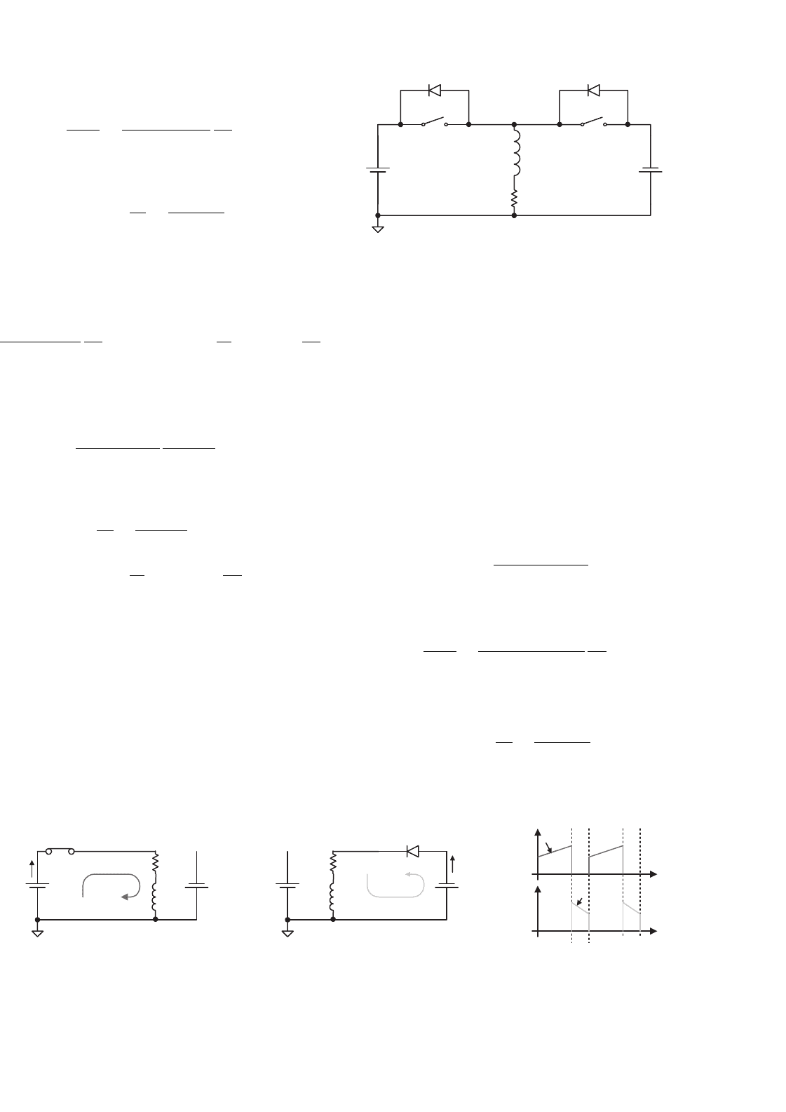
14.10.2 Two-quadrant Switched-inductor
DC/DC Luo-converter in Reverse
Operation
Reverse operation (R) 2Q SI Luo-converter is shown in
Fig. 14.86, and it consists of two switches with two passive
diodes, two inductors, and one capacitor. The source voltage
(V
1
) and load voltage (V
2
) are usually considered as constant
S
1
V
high
V
low
L
1
R
1
i
1
i
I
V
high
V
low
L
1
R
1
i
2
i
o
kT T
kT T
t
t
i
I
i
o
i
1
i
2
D
2
(a) (b) (c)
+
−
+
−
+
−
+
−
FIGURE 14.87 Mode C of F 2Q SI Luo-converter: (a) state-on; S
1
on; (b) state-off: D
2
on, S
1
off; and (c) input and output current waveforms.
D
1
S
1
V
high
V
low
I
high
I
low
S
2
D
2
L
1
R
1
+
−
+
−
FIGURE 14.86 Switched-inductor QIII and IV DC/DC Luo-converter.
voltages. The load can be a battery or motor back EMF. For
example, the source voltage is 42 V and load voltage is −14 V.
There are two modes of operation:
1. Mode C (QIII): electrical energy is transferred from
source side V
1
to load side −V
2
;
2. Mode D (QIV): electrical energy is transferred from
load side −V
2
to source side V
1
.
Mode C: The equivalent circuits during switch-on and -off
periods are shown in Figs. 14.87a and b. The typical output
voltage and current waveforms are shown in Fig. 14.87c.
We have the average inductor current I
L
as
I
L
=
kV
1
−(1 −k)V
2
R
(14.307)
The variation ratio of the inductor current i
L
is
ζ =
i
L
/2
I
L
=
k(1 − k)(V
1
+V
2
)
kV
1
−(1 −k)V
2
R
2fL
(14.308)
The power transfer efficiency is
η
C
=
P
O
P
I
=
(1 −k)V
2
kV
1
(14.309)
322 F. L. Luo and H. Ye
The boundary between continuous and discontinuous
regions is defined as
ζ ≥1, i.e.
k(1−k)(V
1
+V
2
)
kV
1
−(1−k)V
2
R
2fL
≥1ork ≤
V
2
V
1
+V
2
+k(1−k)
R
2fL
(14.310)
Average inductor current I
L
in discontinuous region is
I
L
=
V
1
+V
2
V
2
+RI
L
V
1
−RI
L
2fL
k
2
(14.311)
The power transfer efficiency is
η
C−dis
=
P
O
P
I
=
V
2
V
1
V
1
−RI
L
V
2
+RI
L
with k ≤
V
2
V
1
+V
2
+k(1 − k)
R
2fL
(14.312)
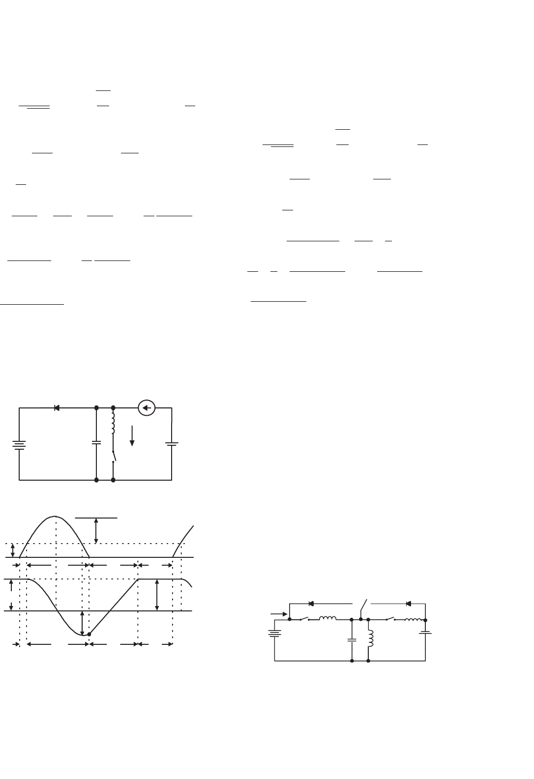
Mode D: The equivalent circuits during switch-on and -off
periods are shown in Figs. 14.88a and b. The typical output
voltage and current waveforms are shown in Fig. 14.88c.
The average inductor current I
L
is
I
L
=
kV
2
−(1 −k)V
1
R
(14.313)
The variation ratio of the inductor current i
L
is
ζ =
i
L
/2
I
L
=
k(1 − k)(V
1
+V
2
)
kV
2
−(1 −k)V
1
R
2fL
(14.314)
The power transfer efficiency is
η
D
=
P
O
P
I
=
(1 −k)V
1
kV
2
(14.315)
S
2
V
high
V
low
L
1
R
1
i
1
i
I
L
1
R
1
i
2
i
o
kT T
kT T
t
t
i
I
i
o
i
1
i
2
D
1
(b)(a) (c)
+
−
V
high
+
−
+
−
V
low
+
−
FIGURE 14.88 Mode D of F 2Q SI Luo-converter: (a) state-on: S
2
on; (b) state-off: D
1
on, S
2
off; and (c) input and output waveforms.
The boundary between continuous and discontinuous
regions is defined as
ζ ≥1, i.e.
k(1−k)(V
1
+V
2
)
kV
2
−(1−k)V
1
R
2fL
≥1ork ≤
V
1
V
1
+V
2
+k(1−k)
R
2fL
(14.316)
Average inductor current I
L
in discontinuous region is
I
L
=
t
4
0
=
V
1
+V
2
V
1
+RI
L
V
2
−RI
L
2fL
k
2
(14.317)
The power transfer efficiency is
η
D−dis
=
P
O
P
I
=
V
1
V
2
V
2
−RI
L
V
1
+RI
L
with k ≤
V
1
V
1
+V
2
+k(1 − k)
R
2fL
(14.318)
14.10.3 Four-quadrant Switched-inductor
DC/DC Luo-converter
Switched-inductor DC/DC converters successfully overcome
the disadvantage of switched-capacitor converters. Usually,
only one inductor is required for each converter with one-
or two- or four-quadrant operation, no matter how large the
difference between the input and output voltage is. There-
fore, switched-inductor converter has very simple topology
and circuit. Consequently, it has high power density. This
paper introduces a switched-inductor four-quadrant DC/DC
Luo-converter.
This converter, shown in Fig. 14.89, consists of three
switches, two diodes, and only one inductor L. The source volt-
age V
1
and load voltage V
2
(e.g. a battery or DC motor back
EMF) are usually constant voltages. R is the equivalent resis-
tance of the circuit, it is usually small. In this paper, V
1
> |V
2
|,
14 DC/DC Conversion Technique and 12 Series Luo-converters 323
S
1
S
2
I
I
L
1
V
1
V
2
I
2
R
1
D
2
D
1
3,4 1,2 3,4
1,2
+
_
Switch S
FIGURE 14.89 Four-quadrant switched-inductor DC/DC Luo-converter.
they are supposed as +42 V and ±14 V, respectively. There-
fore, there are four-quadrants (modes) of operation:
1. Mode A: energy is transferred from source to positive
voltage load; the first-quadrant operation, Q
I
;
2. Mode B: energy is transferred from positive voltage
load to source; the second-quadrant operation, Q
II
;
3. Mode C: energy is transferred from source to negative
voltage load; the third-quadrant operation, Q
III
;
4. Mode C: energy is transferred from negative voltage
load to source; the fourth-quadrant operation, Q
IV
.
The first-quadrant is so-called the forward motoring (Forw.
Mot.) operation. V
1
and V
2
are positive, and I
1
and I
2
are
positive as well. The second-quadrant is so-called the forward
regenerative (Forw. Reg.) braking operation. V
1
and V
2
are
positive, and I
1
and I
2
are negative. The third-quadrant is
so-called the reverse motoring (Rev. Mot.) operation. V
1
and
I
1
are positive, and V
2
and I
2
are negative. The fourth-quadrant
is so-called the reverse regenerative (Rev. Reg.) braking oper-
ation. V
1
and I
2
are positive, and I
1
and V
2
are negative. Each
mode has two states: “on” and “off.” Usually, each state is oper-
ating in different conduction duty k. The switching period is T,
where T = 1/f . The switch status is shown in Table 14.7.
Mode A is shown in Fig. 14.84. During switch-on state,
switch S
1
is closed. In this case the source voltage V
1
supplies
the load V
2
and inductor L, inductor current i
L
increases.
TABLE 14.7 Switch’s status (mentioned switches are not off)
Q no. State S
1
D
1
S
2
D
2
S
3
Source Load
Q
I
, Mode A ON ON ON 1/2 V
1
+ V
2
+
Forw. Mot. OFF ON ON 1/2 I
1
+ I
2
+
Q
II
, Mode B ON ON ON 1/2 V
1
+ V
2
+
Forw. Reg. OFF ON ON 1/2 I
1
− I
2
−
Q
III
, Mode C ON ON ON 3/4 V
1
+ V
2
−
Rev. Mot. OFF ON ON 3/4 I
1
+ I
2
−
Q
IV
, Mode D ON ON ON 3/4 V
1
+ V
2
−
Rev. Reg. OFF ON ON 3/4 I
1
− I
2
+
During switch-off state, diode D
2
is on. In this case current i
L
flows through the load V
2
via the free-wheeling diode D
2
, and
it decreases.
Mode B is shown in Fig. 14.85. During switch-on state,
switch S
2
is closed. In this case the load voltage V
2
supplies the
inductor L, inductor current i
L
increases. During switch-off
state, diode D
1
is on, current i
L
flows through the source V
1
and load V
2
via the diode D
1
, and it decreases.
Mode C is shown in Fig. 14.87. During switch-on state,
switch S
1
is closed. The source voltage V
1
supplies the induc-
tor L, inductor current i
L
increases. During switch-off state,
diode D
2
is on. Current i
L
flows through the load V
2
via the
free-wheeling diode D
2
, and it decreases.
Mode D is shown in Fig. 14.88. During switch-on state,
switch S
2
is closed. The load voltage V
2
supplies the induc-
tor L, inductor current i
L
increases. During switch-off state,
diode D
1
is on. Current i
L
flows through the source V
1
via the
diode D
1
, and it decreases.
All description of the Modes A, B, C, and D is same as in
Sections 14.10.1 and 14.10.2.
14.11 Multi-quadrant ZCS
Quasi-resonant Luo-converters
Soft-switching converters are the fourth-generation converters.
These converters are made of only inductor or capacitors. They
usually perform in the systems between two voltage sources:
V
1
and V
2
. Voltage source V
1
is proposed positive voltage and
voltage V
2
is the load voltage that can be positive or negative.
In the investigation, both voltages are proposed constant volt-
age. Since V
1
and V
2
are constant value, the voltage transfer
gain is constant. Our interesting research will concentrate on
the working current and the power transfer efficiency η. The
resistance R of the inductor has to be considered for the power
transfer efficiency η calculation.
Reviewing the papers in the literature, we can find that most
of the papers investigating the switched-component converters
324 F. L. Luo and H. Ye
are working in single-quadrant operation. Professor Luo and
colleagues have developed this technique into multi-quadrant
operation. We describe these in this section and the next
sections.
Multi-quadrant ZCS quasi-resonant Luo-converters are the
fourth-generation converters. Because these converters imple-
ment ZCS technique, they have the advantages of high
power density, high power transfer efficiency, low EMI, and
reasonable EMC. They have three modes:
• Two-quadrant ZCS quasi-resonant DC/DC Luo-converter
in forward operation;
• Two-quadrant ZCS quasi-resonant DC/DC Luo-converter
in reverse operation;
• Four-quadrant ZCS quasi-resonant DC/DC Luo-
converter.
The two-quadrant ZCS quasi-resonant DC/DC Luo-
converter in forward operation is derived for the energy
transmission of a dual-voltage system. Both, the source and
load voltages are positive polarity. It performs in the first-
quadrant Q
I
and the second-quadrant Q
II
corresponding to
the DC motor forward operation in motoring and regenerative
braking states.
The two-quadrant ZCS quasi-resonant DC/DC Luo-
converter in reverse operation is derived for the energy
transmission of a dual-voltage system. The source voltage is
positive and load voltage is negative polarity. It performs in
the third-quadrant Q
III
and the fourth-quadrant Q
IV
corre-
sponding to the DC motor reverse operation in motoring and
regenerative braking states.
The four-quadrant ZCS quasi-resonant DC/DC Luo-
converter is derived for the energy transmission of a dual-
voltage system. The source voltage is positive, and load voltage
can be positive or negative polarity. It performs four-quadrant
operation corresponding to the DC motor forward and reverse
operation in motoring and regenerative braking states.
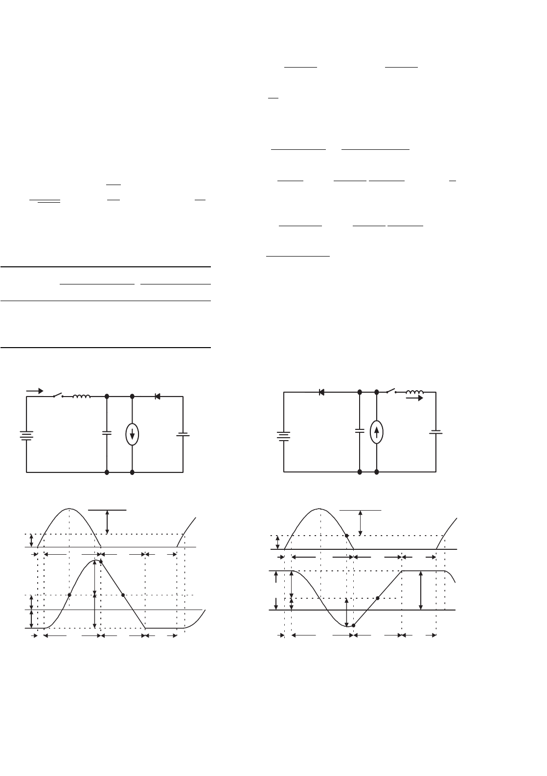
14.11.1 Two-quadrant ZCS Quasi-resonant
Luo-converter in Forward Operation
Since both voltages are low, this converter is designed as
a ZCS quasi-resonant converter (ZCS-QRC). It is shown in
Fig. 14.90. This converter consists of one main inductor L and
V
1
V
2
S
1
S
2
D
1
L
r1
L
r2
C
r
L
i
L
i
1
++
––
D
2
S
a
1
2
FIGURE 14.90 Two-quadrant (QI+QII) DC/DC ZCS quasi-resonant
Luo-converter.
TABLE 14.8 Switch’s status (the blank status means off)
Switch or diode Mode A (QI) Mode B (QII)
State-on State-off State-on State-off
S
1
ON
D
1
ON
S
2
ON
D
2
ON
two switches with their auxiliary components. A switch S
a
is
used for two-quadrant operation. Assuming the main induc-
tance is sufficiently large, the current i
L
is constant. The source
voltage V
1
and load voltage V
2
are usually constant, V
1
= 42 V
and V
2
= 14 V. There are two modes of operation:
1. Mode A (Quadrant I): electrical energy is transferred
from V
1
side to V
2
side, switch S
a
links to D
2
;
2. Mode B (Quadrant II): electrical energy is transferred
from V
2
side to V
1
side, switch S
a
links to D
1
.
Each mode has two states: “on” and “off.” The switch status
of each state is shown in Table 14.8.
Mode A is a ZCS buck converter. The equivalent circuit,
current, and voltage waveforms are shown in Fig. 14.91. There
are four time regions for the switching on and off period. The
conduction duty cycle is k = (t
1
+t
2
) when the input current
S
1
D
2
C
r
L
r1
i
Lr1
I
L
V
1
V
C
+
−
+
−
V
2
+
−
(a)
(b)
I
L
i
Lr1
V
1
/Z
1
V
1
0
0
v
c
V
1
t
1
t
2
t
3
t
4
t
1
t
2
t
3
t
4
v
c0
FIGURE 14.91 Mode A operation: (a) equivalent circuit and
(b) waveforms.
14 DC/DC Conversion Technique and 12 Series Luo-converters 325
flows through the switch S
1
and inductor L. The whole period
is T = (t
1
+t
2
+t
3
+t
4
). Some formulas are listed below
ω
1
=
1
√
L
r1
C
r
; Z
1
=
L
r1
C
r
; i
1−peak
= I
L
+
V
1
Z
1
(14.319)
t
1
=
I
L
L
r1
V
1
; α
1
= sin
−1
I
L
Z
1
V
1
(14.320)
t
2
=
1
ω
1
(π +α
1
); v
CO
= V
1
(1 +cos α
1
) (14.321)
t
3
=
v
CO
C
r
I
L
;
I
L
V
2
V
1
=
t
1
+t
2
T
I
L
+
V
1
Z
1
cos α
1
π/2 +α
1
(14.322)
t
4
=
V
1
(t
1
+t
2
)
V
2
I
L
I
L
+
V
1
Z
1
cos α
1
π/2 +α
1
−(t
1
+t
2
+t
3
);
(14.323)
k =
t
1
+t
2
t
1
+t
2
+t
3
+t
4
; T = t
1
+t
2
+t
3
+t
4
; f = 1/T
(14.324)
Mode B is a ZCS boost converter. The equivalent circuit,
current, and voltage waveforms are shown in Fig. 14.92. There
S
2
D
1
L
r2
i
Lr2
I
L
C
r
V
1
V
C
+
−
+
−
V
2
+
−
(a)
(b)
V
1
0
v
c
V
1
V
1
I
L
i
Lr2
V
1
/Z
2
0
t
1
t
2
t
3
t
4
t
1
t
2
t
3
t
4
v
c0
FIGURE 14.92 Mode B operation: (a) equivalent circuit and (b)
waveforms.
are four time regions for the switching on and off period. The
conduction duty cycle is k = (t
1
+t
2
), but the output current
only flows through the source V
1
in the period t
4
. The whole
period is T = (t
1
+ t
2
+ t
3
+ t
4
). Some formulas are listed
below
ω
2
=
1
√
L
r2
C
r
; Z
2
=
L
r2
C
r
; i
2−peak
=I
L
+
V
1
Z
2
(14.325)
t
1
=
I
L
L
r2
V
1
; α
2
=sin
−1
I
L
Z
2
V
1
(14.326)
t
2
=
1
ω
2
(π+α
2
); v
CO
=−V
1
cosα
2
(14.327)
t
3
=
(V
1
−v
CO
)C
r
I
L
;
I
L
V
2
V
1
=
t
4
T
I
L
(14.328)
V
2
V
1
=
t
4
T
=
t
4
t
1
+t
2
+t
3
+t
4
; t
4
=
t
1
+t
2
+t
3
(V
1
/V
2
)−1
(14.329)
k =
t
1
+t
2
t
1
+t
2
+t
3
+t
4
; T =t
1
+t
2
+t
3
+t
4
; f =1/T (14.330)
14.11.2 Two-quadrant ZCS Quasi-resonant
Luo-converter in Reverse Operation
Two-quadrant ZCS quasi-resonant Luo-converter in reverse
operation is shown in Fig. 14.93. It is a new soft-switching tech-
nique with two-quadrant operation, which effectively reduces
the power losses and largely increases the power transfer effi-
ciency. It consists of one main inductor L and two switches
with their auxiliary components. A switch S
a
is used for
two-quadrant operation. Assuming the main inductance L is
sufficiently large, the current i
L
is constant. The source voltage
V
1
and load voltage V
2
are usually constant, e.g. V
1
= 42 V
and V
2
=−28 V. There are two modes of operation:
1. Mode C (Quadrant III): electrical energy is transferred
from V
1
side to −V
2
side, switch S
a
links to D
2
;
2. Mode D (Quadrant IV): electrical energy is transferred
from −V
2
side to V
1
side, switch S
a
links to D
1
.
S
1
S
2
L
r2
L
r1
C
r
L
D
1
i
1
V
1
+
–
V
2
+
–
D
2
S
a
43
FIGURE 14.93 Two-quadrant (QIII+IV) DC/DC ZCS quasi-resonant
Luo-converter.
326 F. L. Luo and H. Ye
Each mode has two states: “on” and “off.” The switch status
of each state is shown in Table 14.9.
Mode C is a ZCS buck–boost converter. The equivalent cir-
cuit, current, and voltage waveforms are shown in Fig. 14.94.
There are four time regions for the switching on and off period.
The conduction duty cycle is kT = (t
1
+ t
2
) when the input
current flows through the switch S
1
and the main inductor L.
The whole period is T = (t
1
+ t
2
+ t
3
+ t
4
). Some formulas
are listed below
ω
1
=
1
√
L
r1
C
r
; Z
1
=
L
r1
C
r
; i
1−peak
= I
L
+
V
1
Z
1
(14.331)
TABLE 14.9 Switch’s status (the blank status means off)
Switch or diode Mode C (QIII) Mode D (QIV)
State-on State-off State-on State-off
S
1
ON
D
1
ON
S
2
ON
D
2
ON
S
1
D
2
L
r1
i
Lr1
I
L
C
r
V
1
V
C
+
−
+
−
V
2
−
+
(a)
(b)
V
1
−V
2
V
2
V
1
V
1
v
c
I
L
i
Lr1
(V
1
+V
2
)/Z
1
0
0
t
2
'
t
1
t
2
t
3
t
4
t
1
t
2
t
3
t
3
'
t
4
v
c0
FIGURE 14.94 Mode C operation: (a) equivalent circuit and (b)
waveforms.
t
1
=
I
L
L
r1
V
1
+V
2
; α
1
= sin
−1
I
L
Z
1
V
1
+V
2
(14.332)
t
2
=
1
ω
1
(π +α
1
); v
CO
= (V
1
−V
2
) +V
1
sin(π/2 +α
1
)
= V
1
(1 +cos α
1
) −V
2
(14.333)
t
3
=
(v
CO
+V
2
)C
r
I
L
=
V
1
(1 +cos α
1
)C
r
I
L
;
I
1
=
t
1
+t
2
T
I
L
+
V
1
+V
2
Z
1
cos α
1
π/2 +α
1
; I
2
=
t
4
T
I
L
(14.334)
t
4
=
V
1
(t
1
+t
2
)
V
2
I
L
I
L
+
V
1
+V
2
Z
1
cos α
1
π/2 +α
1
(14.335)
k =
t
1
+t
2
t
1
+t
2
+t
3
+t
4
; T = t
1
+t
2
+t
3
+t
4
; f = 1/T
(14.336)
Mode D is a cross ZCS buck–boost converter. The equiv-
alent circuit, current, and voltage waveforms are shown in
Fig. 14.95. There are four time regions for the switching on
and off period. The conduction duty cycle is kT = (t
1
+ t
2
),
but the output current only flows through the source V
1
in
S
2
D
1
L
r2
i
Lr2
I
L
C
r
V
1
V
C
+
−
+
−
V
2
−
+
(a)
(b)
V
1
−V
2
V
2
V
2
V
1
V
1
v
c
I
L
i
Lr2
0
0
t
2
'
t
3
'
t
1
t
2
t
3
t
4
t
1
t
2
t
3
t
4
v
c0
(V
1
+V
2
)/Z
2
FIGURE 14.95 Mode D operation: (a) equivalent circuit and (b)
waveforms.
14 DC/DC Conversion Technique and 12 Series Luo-converters 327
the period t
4
. The whole period is T = (t
1
+ t
2
+ t
3
+ t
4
).
Some formulas are listed below
ω
2
=
1
√
L
r2
C
r
; Z
2
=
L
r2
C
r
; i
2−peak
= I
L
+
V
2
Z
2
(14.337)
t
1
=
I
L
L
r2
V
1
+V
2
; α
2
= sin
−1
I
L
Z
2
V
2
+V
2
(14.338)
t
2
=
1
ω
2
(π +α
2
); v
CO
= (V
1
−V
2
) −V
2
sin(π/2 +α
2
)
= V
1
−V
2
(1 +cos α
2
) (14.339)
t
3
=
(V
1
−v
CO
)C
r
I
L
=
V
2
(1 +cos α
2
)C
r
I
L
;
I
2
=
t
1
+t
2
T
I
L
+
V
1
+V
2
Z
2
cos α
2
π/2 +α
2
; I
1
=
t
4
T
I
L
(14.340)
t
4
=
V
2
(t
1
+t
2
)
V
1
I
L
I
L
+
V
1
+V
2
Z
2
cos α
2
π/2 +α
2
(14.341)
k =
t
1
+t
2
t
1
+t
2
+t
3
+t
4
; T = t
1
+t
2
+t
3
+t
4
; f = 1/T
(14.342)
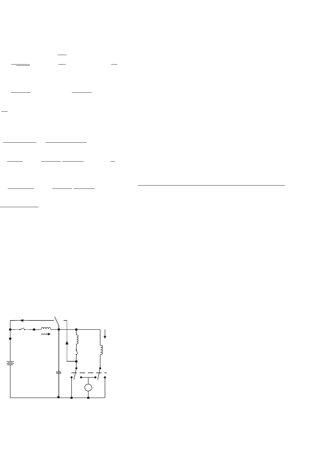
14.11.3 Four-quadrant ZCS Quasi-resonant
Luo-converter
Four-quadrant ZCS quasi-resonant Luo-converter is shown
in Fig. 14.96. Circuit 1 implements the operation in quad-
rants I and II, circuit 2 implements the operation in quadrants
III and IV. Circuit 1 and 2 can be converted to each other by
auxiliary switch. Each circuit consists of one main inductor L
and two switches. A switch S
a
is used for four-quadrant opera-
tion. Assuming that the main inductance L is sufficiently large,
S
1
S
2
S
3
i
r
C
r
i
L
D
1
V
1
+
–
V
2
D
2
S
a
L
r1
L
–
+
1/2
1/2
3/4
3/4
L
r2
1/3
2/4
FIGURE 14.96 Four-quadrant DC/DC ZCS quasi-resonant Luo-
converter.
the current i
L
remains constant. The source and load voltages
are usually constant, e.g. V
1
= 42 V and V
2
=±28 V [7–9].
There are four modes of operation:
1. Mode A (Quadrant I): electrical energy is transferred
from V
1
side to V
2
side, switch S
a
links to D
2
;
2. Mode B (Quadrant II): electrical energy is transferred
from V
2
side to V
1
side, switch S
a
links to D
1
;
3. Mode C (Quadrant III): electrical energy is transferred
from V
1
side to −V
2
side, switch S
a
links to D
2
;
4. Mode D (Quadrant IV): electrical energy is transferred
from −V
2
side to V
1
side, switch S
a
links to D
1
.
Each mode has two states: “on” and “off.” The switch status
of each state is shown in Table 14.10.
The operation of Mode A, B, C, and D is same as in the
previous Sections 14.11.1 and 14.11.2.
14.12 Multi-quadrant ZVS
Quasi-resonant Luo-converters
Multi-quadrant ZVS quasi-resonant Luo-converters are the
fourth-generation converters. Because these converters imple-
ment ZCS technique, they have the advantages of high
power density, high power transfer efficiency, low EMI, and
reasonable EMC. They have three modes:
•
Two-quadrant ZVS quasi-resonant DC/DC Luo-converter
in forward operation;
• Two-quadrant ZVS quasi-resonant DC/DC Luo-converter
in reverse operation;
• Four-quadrant ZVS quasi-resonant DC/DC Luo-
converter.
The two-quadrant ZVS quasi-resonant DC/DC Luo-
converter in forward operation is derived for the energy
transmission of a dual-voltage system. Both, the source and
load voltages are positive polarity. It performs in the first-
quadrant Q
I
and the second-quadrant Q
II
corresponding to
the DC motor forward operation in motoring and regenerative
braking states.
The two-quadrant ZVS quasi-resonant DC/DC Luo-
converter in reverse operation is derived for the energy
transmission of a dual-voltage system. The source voltage is
positive and load voltage is negative polarity. It performs in
the third-quadrant Q
III
and the fourth-quadrant Q
IV
corre-
sponding to the DC motor reverse operation in motoring and
regenerative braking states.
The four-quadrant ZVS quasi-resonant DC/DC Luo-
converter is derived for the energy transmission of a dual-
voltage system. The source voltage is positive, and load voltage
can be positive or negative polarity. It performs four-quadrant
operation corresponding to the DC motor forward and reverse
operation in motoring and regenerative braking states.