Power electronic handbook
Подождите немного. Документ загружается.

328 F. L. Luo and H. Ye
TABLE 14.10 Switch’s status (the blank status means off)
Circuit//switch or diode Mode A (QI) Mode B (QII) Mode C (QIII) Mode D (QIV)
State-on State-off State-on State-off State-on State-off State-on State-off
Circuit Circuit 1 Circuit 2
S
1
ON ON
D
1
ON ON
S
2
ON ON
D
2
ON ON
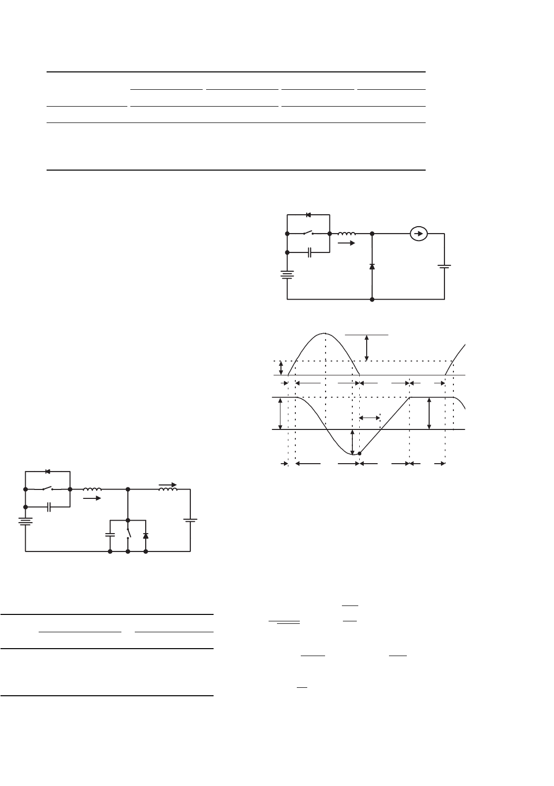
14.12.1 Two-quadrant ZVS Quasi-resonant
DC/DC Luo-converter in Forward
Operation
Two-quadrant ZVS quasi-resonant Luo-converter in forward
operation is shown in Fig. 14.97. It consists of one main
inductor L and two switches with their auxiliary components.
Assuming the main inductance L is sufficiently large, the
current i
L
is constant. The source voltage V
1
and load voltage
V
2
are usually constant, e.g. V
1
= 42 V and V
2
= 14 V. There
are two modes of operation:
1. Mode A (Quadrant I): electrical energy is transferred
from V
1
side to V
2
side;
2. Mode B (Quadrant II): electrical energy is transferred
from V
2
side to V
1
side.
Each mode has two states: “on” and “off.” The switch status
of each state is shown in Table 14.11.
Mode A is a ZVS buck converter shown in Fig. 14.98. There
are four time regions for the switching on and off period.
V
1
V
2
S
1
S
2
D
1
D
2
L
r
C
r2
L
i
L
i
r
C
r1
+
−
+
−
FIGURE 14.97 Two-quadrant (QI+QII) DC/DC ZVS quasi-resonant
Luo-converter.
TABLE 14.11 Switch’s status (the blank status means off)
Switch Mode A (QI) Mode B (QII)
State-on State-off State-on State-off
S
1
ON
D
1
ON
S
2
ON
D
2
ON
V
1
S
1
D
2
L
r
I
L
i
r
+−
v
c1
D
1
C
r1
+
+
−
−
V
2
(a)
V
1
v
C1
Z
1
I
L
I
L
0
0
i
r
t
1
t
2
t
3
t
4
t
1
t
2
t
3
t
4
i
r01
I
L
t
3
'
I
L
(b)
FIGURE 14.98 Mode A operation: (a) equivalent circuit and (b)
waveforms.
The conduction duty cycle is kT = (t
3
+ t
4
) when the input
current flows through the switch S
1
and the main inductor L.
The whole period is T = (t
1
+ t
2
+ t
3
+ t
4
). Some relevant
formulas are listed below
ω
1
=
1
√
L
r
C
r1
; Z
1
=
L
r
C
r1
; v
c1−peak
=V
1
+Z
1
I
L
(14.343)
t
1
=
V
1
C
r1
I
L
; α
1
=sin
−1
V
1
Z
1
I
L
(14.344)
t
2
=
1
ω
1
(π+α
1
); i
rO1
=−I
L
cosα
1
(14.345)

14 DC/DC Conversion Technique and 12 Series Luo-converters 329
t
3
=
(I
L
−i
rO1
)L
r
V
1
; I
1
=
I
L
V
2
V
1
=
1
T
t
4
t
3
i
r
dt ≈
1
T
(I
L
t
4
)=
t
4
T
I
L
(14.346)
t
4
=
t
1
+t
2
+t
3
(V
1
/V
2
)−1
(14.347)
k =
t
3
+t
4
t
1
+t
2
+t
3
+t
4
; T =t
1
+t
2
+t
3
+t
4
; f =1/T (14.348)
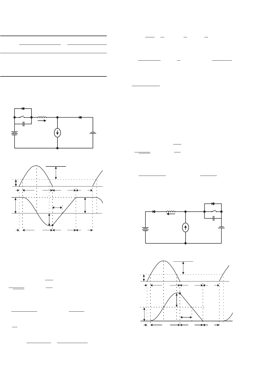
Mode B is a ZVS boost converter shown in Fig. 14.99. There
are four time regions for the switching on and off period. The
conduction duty cycle is kT = (t
3
+t
4
), but the output current
only flows through the source V
1
in the period (t
1
+ t
2
). The
whole period is T = (t
1
+t
2
+t
3
+t
4
). Some relevant formulas
are listed below
ω
2
=
1
√
L
r
C
r2
; Z
2
=
L
r
C
r2
; v
C2−peak
= V
1
+Z
2
I
L
(14.349)
t
1
=
V
1
C
r2
I
L
; α
2
= sin
−1
V
1
Z
2
I
L
(14.350)
V
1
I
L
D
1
L
r
+
−
v
c2
i
r
S
2
D
2
C
r2
+
−
+
−
V
2
(a)
(b)
V
1
v
C2
Z
2
I
L
0
0
i
r
t
1
t
2
t
3
t
4
t
1
t
2
t
3
t
4
i
r02
I
L
I
L
t
3
'
FIGURE 14.99 Mode B operation: (a) equivalent circuit and (b)
waveforms.
t
2
=
1
ω
2
(π +α
2
); i
rO2
= I
L
(1 +cos α
2
) (14.351)
t
3
=
i
rO2
L
r
V
1
;
I
1
=
I
L
V
2
V
1
=
1
T
t
3
t
1
i
r
dt ≈
1
T
I
L
t
2
+t
3
=
t
2
+t
3
T
I
L
;
or
V
2
V
1
=
1
T
(t
2
+t
3
) =
t
2
+t
3
t
1
+t
2
+t
3
+t
4
(14.352)
t
4
=
V
1
V
2
−1
(t
2
+t
3
) −t
1
; (14.353)
k =
t
3
+t
4
t
1
+t
2
+t
3
+t
4
; T = t
1
+t
2
+t
3
+t
4
; f = 1/T
(14.354)
14.12.2 Two-quadrant ZVS Quasi-resonant
DC/DC Luo-converter in Reverse
Operation
Two-quadrant ZVS quasi-resonant Luo-converter in reverse
operation is shown in Fig. 14.100. It consists of one main
inductor L and two switches with their auxiliary components.
Assuming the main inductance L is sufficiently large, the cur-
rent i
L
is constant. The source voltage V
1
and load voltage V
2
are usually constant, e.g. V
1
=+42 V and V
2
=−28 V. There
are two modes of operation:
1. Mode C (Quadrant III): electrical energy is transferred
from V
1
side to −V
2
side;
2. Mode D (Quadrant IV): electrical energy is transferred
from −V
2
side to V
1
side.
Each mode has two states: “on” and “off.” The switch status
of each state is shown in Table 14.12.
Mode C is a ZVS buck–boost converter shown in
Fig. 14.101. There are four time regions for the switching on
and off period. The conduction duty cycle is kT = (t
3
+ t
4
)
when the input current flows through the switch S
1
and the
main inductor L. The whole period is T = (t
1
+t
2
+t
3
+t
4
).
V
1
V
2
S
1
S
2
D
1
D
2
L
r
C
r1
L
i
r
+
−
−
+
i
L
C
r2
FIGURE 14.100 Two-quadrant (QIII+IV) DC/DC ZVS quasi-resonant
Luo-converter.
330 F. L. Luo and H. Ye
TABLE 14.12 Switch’s status (the blank status means off)
Switch Mode C (QIII) Mode D (QIV)
State-on State-off State-on State-off
S
1
ON
D
1
ON
S
2
ON
D
2
ON
V
1
S
1
D
2
L
r
C
r1
I
L
i
r
V
c1
+
−
V
2
−
+
+−
D
1
(a)
(b)
V
1
+V
2
v
C1
Z
1
I
L
I
L
0
0
i
r
t
1
t
2
t
3
t
4
t
1
t
2
t
3
t
4
i
r01
I
L
t
3
'
I
L
FIGURE 14.101 Mode C operation: (a) equivalent circuit and (b)
waveforms.
Some formulas are listed below
ω
1
=
1
√
L
r
C
r1
; Z
1
=
L
r
C
r1
; v
c1−peak
=V
1
+V
2
+Z
1
I
L
(14.355)
t
1
=
(V
1
+V
2
)C
r1
I
L
; α
1
=sin
−1
V
1
+V
2
Z
1
I
L
(14.356)
t
2
=
1
ω
1
(π+α
1
); i
rO1
=−I
L
sin(π/2+α
1
) (14.357)
t
3
=
(I
L
−i
rO1
)L
r
V
1
+V
2
=
I
L
(1+cosα
1
)L
r
V
1
+V
2
;
I
1
=
I
L
V
2
V
1
=
1
T
t
4
t
3
i
r
dt ≈
1
T
(I
L
t
4
)=
t
4
T
I
L
(14.358)
t
4
=
t
1
+t
2
+t
3
(V
1
/V
2
)−1
; I
2
=
1
T
t
3
t
1
(I
L
−i
r
)dt ≈
t
1
+t
2
+t
3
T
I
L
(14.359)
k =
t
3
+t
4
t
1
+t
2
+t
3
+t
4
; T =t
1
+t
2
+t
3
+t
4
; f =1/T (14.360)
Mode D is a cross ZVS buck–boost converter shown in
Fig. 14.102. There are four time regions for the switching on
and off period. The conduction duty cycle is kT = (t
3
+ t
4
),
but the output current only flows through the source V
1
in the
period (t
1
+ t
2
). The whole period is T = (t
1
+ t
2
+ t
3
+ t
4
).
Some formulae are listed below
ω
2
=
1
√
L
r
C
r2
; Z
2
=
L
r
C
r2
; v
C2−peak
= V
1
+V
2
+Z
2
I
L
(14.361)
t
1
=
(V
1
+V
2
)C
r2
I
L
; α
2
= sin
−1
V
1
+V
2
Z
2
I
L
(14.362)
+−
V
1
C
r2
I
L
D
1
S
2
V
c2
i
r
+
−
L
r
V
2
−
+
D
2
(a)
(b)
V
1
+V
2
v
C2
Z
2
I
L
I
L
0
0
i
r
t
1
t
2
t
3
t
4
t
1
t
2
t
3
t
4
i
r02
t
3
'
I
L
FIGURE 14.102 Mode D operation: (a) equivalent circuit and (b)
waveforms.
14 DC/DC Conversion Technique and 12 Series Luo-converters 331
t
2
=
1
ω
2
(π +α
2
); i
rO2
= I
L
[1 +sin(π/2 +α
2
)] (14.363)
t
3
=
i
rO2
L
r
V
1
+V
2
=
I
L
(1 +cos α
2
)L
r
V
1
+V
2
;
I
1
=
1
T
t
3
t
1
i
r
dt ≈
t
1
+t
2
+t
3
T
I
L
;
I
2
=
1
T
t
4
t
3
i
r
dt ≈
1
T
(I
L
t
4
) =
t
4
T
I
L
;
V
2
V
1
=
1
T
(t
1
+t
2
+t
3
) =
t
1
+t
2
+t
3
t
1
+t
2
+t
3
+t
4
(14.364)
t
4
=
V
1
V
2
−1
(t
1
+t
2
+t
3
) (14.365)
k =
t
3
+t
4
t
1
+t
2
+t
3
+t
4
; T = t
1
+t
2
+t
3
+t
4
; f = 1/T
(14.366)
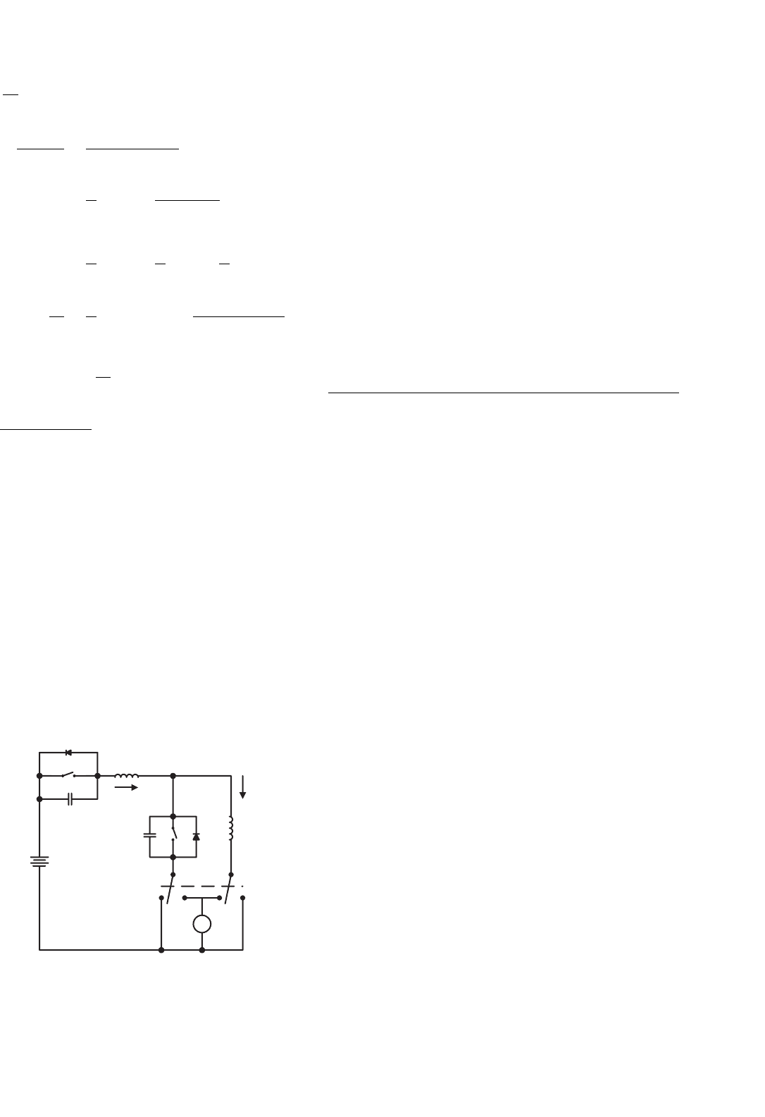
14.12.3 Four-quadrant ZVS Quasi-resonant
DC/DC Luo-converter
Four-quadrant ZVS quasi-resonant Luo-converter is shown in
Fig. 14.103. Circuit 1 implements the operation in quadrants
I and II, circuit 2 implements the operation in quadrants III
and IV. Circuit 1 and 2 can be converted to each other by
auxiliary switch. Each circuit consists of one main inductor L
and two switches. Assuming that the main inductance L is suf-
ficiently large, the current i
L
is constant. The source and load
voltages are usually constant, e.g. V
1
= 42 V and V
2
=±28 V.
There are four modes of operation:
V
1
S
1
S
2
D
1
D
2
L
r
C
r2
L
i
L
i
r
C
r1
+
−
V
2
−
+
ab ab cdcd
S
3
FIGURE 14.103 Four-quadrant DC/DC ZVS quasi-resonant Luo-
converter.
• Mode A (Quadrant I): electrical energy is transferred
from V
1
side to V
2
side;
• Mode B (Quadrant II): electrical energy is transferred
from V
2
side to V
1
side;
• Mode C (Quadrant III): electrical energy is transferred
from V
1
side to −V
2
side;
• Mode D (Quadrant IV): electrical energy is transferred
from −V
2
side to V
1
side.
Each mode has two states: “on” and “off.” The switch status
of each state is shown in Table 14.13.
The description of Modes A, B, C, and D is same as in the
previous Sections 14.12.1 and 14.12.2.
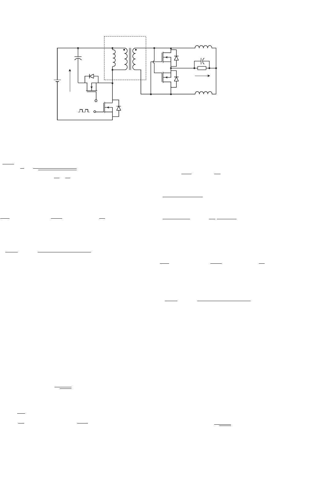
14.13 Synchronous-rectifier DC/DC
Luo-converters
Synchronous-rectifier (SR) DC/DC converters are called the
fifth-generation converters. The development of the micro-
electronics and computer science requires the power supplies
with low output voltage and strong current. Traditional
diode bridge rectifiers are not available for this requirement.
Soft-switching technique can be applied in SR DC/DC con-
verters. We have created few converters with very low voltage
(5 V, 3.3 V, and 1.8 ∼1.5 V) and strong current (30 A, 60 A up
to 200 A) and high power transfer efficiency (86%, 90% up
to 93%). In this section, few new circuits, different from the
ordinary SR DC/DC converters, are introduced:
•
Flat transformer synchronous-rectifier DC/DC Luo-
converter;
• Double current synchronous-rectifier DC/DC Luo-
converter with active clamp circuit;
• Zero-current-switching synchronous-rectifier DC/DC
Luo-converter;
• Zero-voltage-switching synchronous-rectifier DC/DC
Luo-converter.
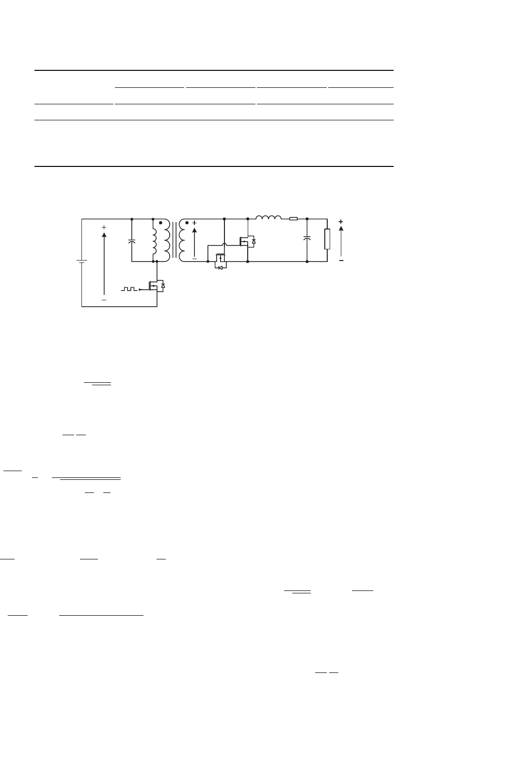
14.13.1 Flat Transformer Synchronous-rectifier
DC/DC Luo-converter
Flat transformer SR DC/DC Luo-converter is shown in
Fig. 14.104. The switches S
1
,S
2
, and S
3
are the low-resistance
MOSFET devices with very low resistance R
S
(7–8 m). Since
we use a flat transformer, the leakage inductance L
m
and
resistance R
L
are small. Other parameters are C = 1 µF,
L
m
= 1 nH, R
L
= 2m, L = 5 µH, C
O
= 10 µF. The input
voltage is V
1
= 30 VDC and output voltage is V
2
, the output
current is I
O
. The transformer term’s ratio is N = 12 : 1. The
repeating period is T = 1/f and conduction duty is k. There
are four working modes.
332 F. L. Luo and H. Ye
TABLE 14.13 Switch’s status (the blank status means off)
Circuit//switch or diode Mode A (QI) Mode B (QII) Mode C (QIII) Mode D (QIV)
State-on State-off State-on State-off State-on State-off State-on State-off
Circuit Circuit 1 Circuit 2
S
1
ON ON
D
1
ON ON
S
2
ON ON
D
2
ON ON
PWM
C
L
m
T
N : 1
C
O
V
1
R v
2
L
R
L
v
3
S
3
S
2
S
1
D
3
D
2
FIGURE 14.104 Flat transformer SR Luo-converter.
The natural resonant frequency is
ω =
1
√
L
m
C
(14.367)
The intervals are
t
1
=
L
m
V
1
I
O
N
; t
2
≈ kT; (14.368)
t
3
=
L
m
C
π
2
+
V
1
V
2
1
+
L
m
C
I
O
N
2
; t
4
≈ (1 −k)T
(14.369)
Average output voltage V
2
and input current I
1
are
V
2
=
kV
1
N
−
R
L
+R
S
+
L
m
TN
2
I
O
; I
1
= k
I
O
N
(14.370)
The power transfer efficiency is
η =
V
2
I
O
V
1
I
1
= 1 −
R
L
+R
S
+(L
m
/TN
2
)
kV
1
/N
I
O
(14.371)
When we set the frequency f = 150–200 kHz, we obtained
the V
2
=1.8 V, N =12, I
O
=0–30 A, Volume =2.5 in
3
. The
average power transfer efficiency is 92.3% and the maximum
power density (PD) is 21.6 W/in
3
.
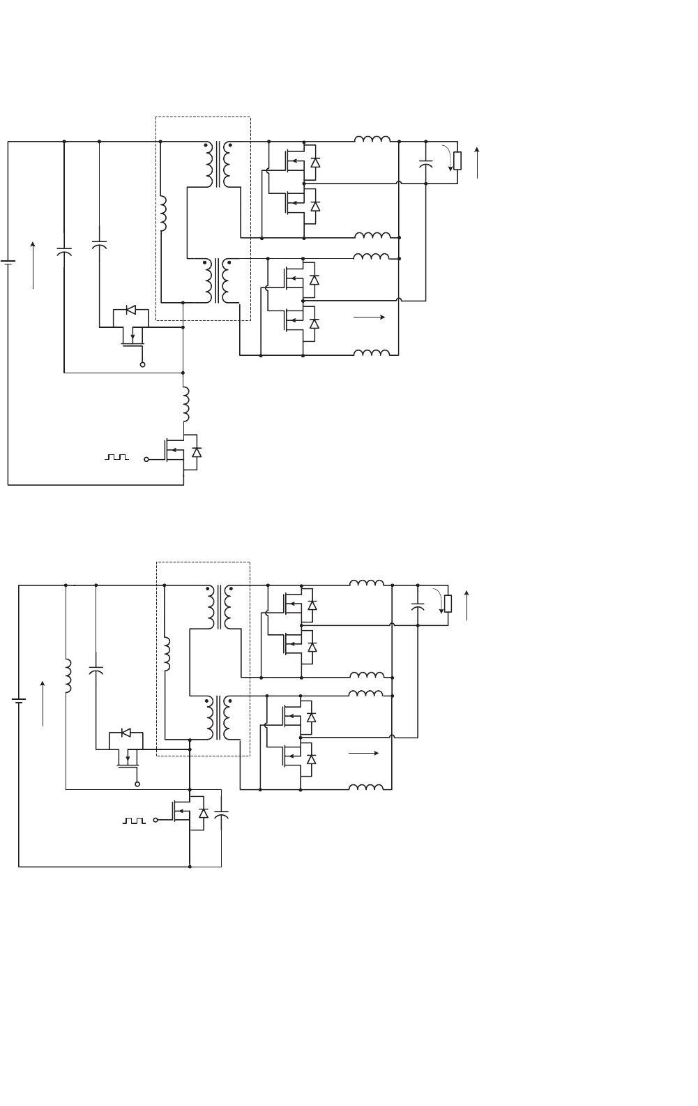
14.13.2 Double Current SR DC/DC
Luo-converter with Active
Clamp Circuit
The converter in Fig. 14.104 resembles a half-wave rectifier.
Double current (DC) SR DC/DC Luo-converter with active
clamp circuit is shown in Fig. 14.105. The switches S
1
–S
4
are
the low-resistance MOSFET devices with very low resistance
R
S
(7–8 m). Since S
3
and S
4
plus L
1
and L
2
form a double
current circuit and S
2
plus C is the active clamp circuit, this
converter resembles a full-wave rectifier and obtains strong
output current. Other parameters are C = 1 µF, L
m
= 1 nH,
R
L
= 2m, L = 5 µH, C
O
= 10 µF. The input voltage is
V
1
= 30 VDC and output voltage is V
2
, the output current is
I
O
. The transformer term’s ratio is N = 12 : 1. The repeating
period is T = 1/f and conduction duty is k. There are four
working modes.
The natural resonant frequency is
ω =
1
√
L
m
C
; V
C
=
k
1 −k
V
1
(14.372)
The interval of t
1
is
t
1
=
L
m
V
1
I
O
N
; t
2
≈ kT; (14.373)
14 DC/DC Conversion Technique and 12 Series Luo-converters 333
+
−
PWM
V
1
C
L
m
FT
S
2
S
1
D
1
D
2
N:1
S
4
S
3
D
3
D
4
L
2
L
1
R
C
O
V
2
+
_
FIGURE 14.105 Double current SR Luo-converter.
t
3
=
L
m
C
π
2
+
V
1
V
2
1
+
L
m
C
I
O
N
2
; t
4
≈ (1 −k)T
(14.374)
Average output voltage V
2
and input current I
1
are
V
2
=
kV
1
N
−
R
L
+R
S
+
L
m
TN
2
I
O
; I
1
= k
I
O
N
(14.375)
The power transfer efficiency
η =
V
2
I
O
V
1
I
1
= 1 −
R
L
+R
S
+(L
m
/TN
2
)
kV
1
/N
I
O
(14.376)
When we set the frequency f = 200–250 kHz, we obtained
the V
2
= 1.8 V, N = 12, I
O
=0–35 A, Volume = 2.5 in
3
. The
average power transfer efficiency is 94% and the maximum
power density (PD) is 25 W/in
3
.
14.13.3 Zero-current-switching
Synchronous-rectifier DC/DC
Luo-converter
Since the power loss across the main switch S
1
is high in DC
SR DC/DC Luo-converter, we designed ZCS SR DC/DC Luo-
converter shown in Fig. 14.106. This converter is based on the
DC SR DC/DC Luo-converter plus ZCS technique. It employs
a double core flat transformer.
The ZCS resonant frequency is
ω
r
=
1
√
L
r
C
r
(14.377)
The normalized impedance is
Z
r
=
L
r
C
r
and α = sin
−1
I
1
Z
r
V
1
(14.378)
The intervals are
t
1
=
I
1
L
r
V
1
; t
2
=
1
ω
r
(π +α); (14.379)
t
3
=
V
1
(1 +cos α)C
r
I
1
;
t
4
=
V
1
(t
1
+t
2
)
V
2
I
1
I
L
+
V
1
Z
r
cos α
π/2 +α
−(t
1
+t
2
+t
3
)
(14.380)
Average output voltage V
2
and input current I
1
are
V
2
=
kV
1
N
−
R
L
+R
S
+
L
m
TN
2
I
O
; I
1
= k
I
O
N
(14.381)
The power transfer efficiency
η =
V
2
I
O
V
1
I
1
= 1 −
R
L
+R
S
+(L
m
/TN
2
)
kV
1
/N
I
O
(14.382)
When we set the V
1
= 60 V and frequency f = 200–
250 kHz, we obtained the V
2
= 1.8 V, N = 12, I
O
=0–60 A,
Volume =4in
3
. The average power transfer efficiency is 94.5%
and the maximum power density (PD) is 27 W/in
3
.
14.13.4 Zero-voltage-switching
Synchronous-rectifier DC/DC
Luo-converter
ZVS SR DC/DC Luo-converter is shown in Fig. 14.107. This
converter is based on the DC SR DC/DC Luo-converter plus
ZVS technique. It employs a double core flat transformer.
The ZVS resonant frequency is
ω
r
=
1
√
L
r
C
r
(14.383)
334 F. L. Luo and H. Ye
PWM
C
r
L
m
FT
S
2
S
1
N:1
S
4
S
3
D
3
D
4
L
2
L
1
V
2
+
−
S
6
S
5
D
5
D
6
L
4
V
1
+
−
N:1
C
D
1
D
2
L
r
L
3
C
O
R
I
2
FIGURE 14.106 ZCS DC SR Luo-converter.
PWM
C
r
L
m
FT
S
2
S
1
N:1
S
4
S
3
D
3
D
4
L
2
L
1
V
2
+
−
S
6
S
5
D
5
D
6
L
4
V
1
+
−
N:1
C
D
1
D
2
L
r
L
3
C
O
R
I
2
FIGURE 14.107 ZVS DC SR Luo-converter.
14 DC/DC Conversion Technique and 12 Series Luo-converters 335
The normalized impedance is
Z
r
=
L
r
C
r
; α = sin
−1
V
1
Z
r
I
1
(14.384)
The intervals are
t
1
=
V
1
C
r
I
1
; t
2
=
1
ω
r
(π +α); (14.385)
t
3
=
I
1
(1 +cos α)L
r
V
1
; t
4
=
t
1
+t
2
+t
3
(V
1
/V
2
) −1
(14.386)
Average output voltage V
2
and input current I
1
are
V
2
=
kV
1
N
−
R
L
+R
S
+
L
m
TN
2
I
O
; I
1
= k
I
O
N
(14.387)
The power transfer efficiency
η =
V
2
I
O
V
1
I
1
= 1 −
R
L
+R
S
+(L
m
/TN
2
)
kV
1
/N
I
O
(14.388)
When we set the V
1
= 60 V and frequency f = 200–250 kHz,
we obtained the V
2
= 1.8 V, N = 12, I
O
=0–60 A, Vol-
ume =4in
3
. The average power transfer efficiency is 94.5%
and the maximum power density (PD) is 27 W/in
3
.
14.14 Multiple-element Resonant Power
Converters
Multiple energy-storage elements resonant power converters
(x-Element RPC) are the sixth-generation converters. Accord-
ing to the transferring, power becomes higher and higher,
traditional methods are hardly satisfied to deliver large power
from source to final actuators with high efficiency. In order
to reduce the power losses during the conversion process
the sixth-generation converters – multiple energy-storage ele-
ments resonant power converters (x-Element RPC) – are
created. They can be sorted into two main groups:
• DC/DC resonant converters;
• DC/AC resonant inverters.
Both groups converters consist of multiple energy-storage
elements: two elements, three elements, or four elements.
These energy-storage elements are passive parts: inductors and
capacitors. They can be connected in series or parallel in var-
ious methods. In full statistics, the circuits of the multiple
energy-storage elements converters are:
• 8 topologies of 2-element RPC;
• 38 topologies of 3-element RPC;
• 98 topologies of 4-element (2L-2C) RPC.
How to investigate the large quantity converters is a vital
task. This problem was addressed in the last decade of last
century. Unfortunately, much attention was not paid to it. This
generation converters were not well discussed, only limited
number of papers was published in the literature.
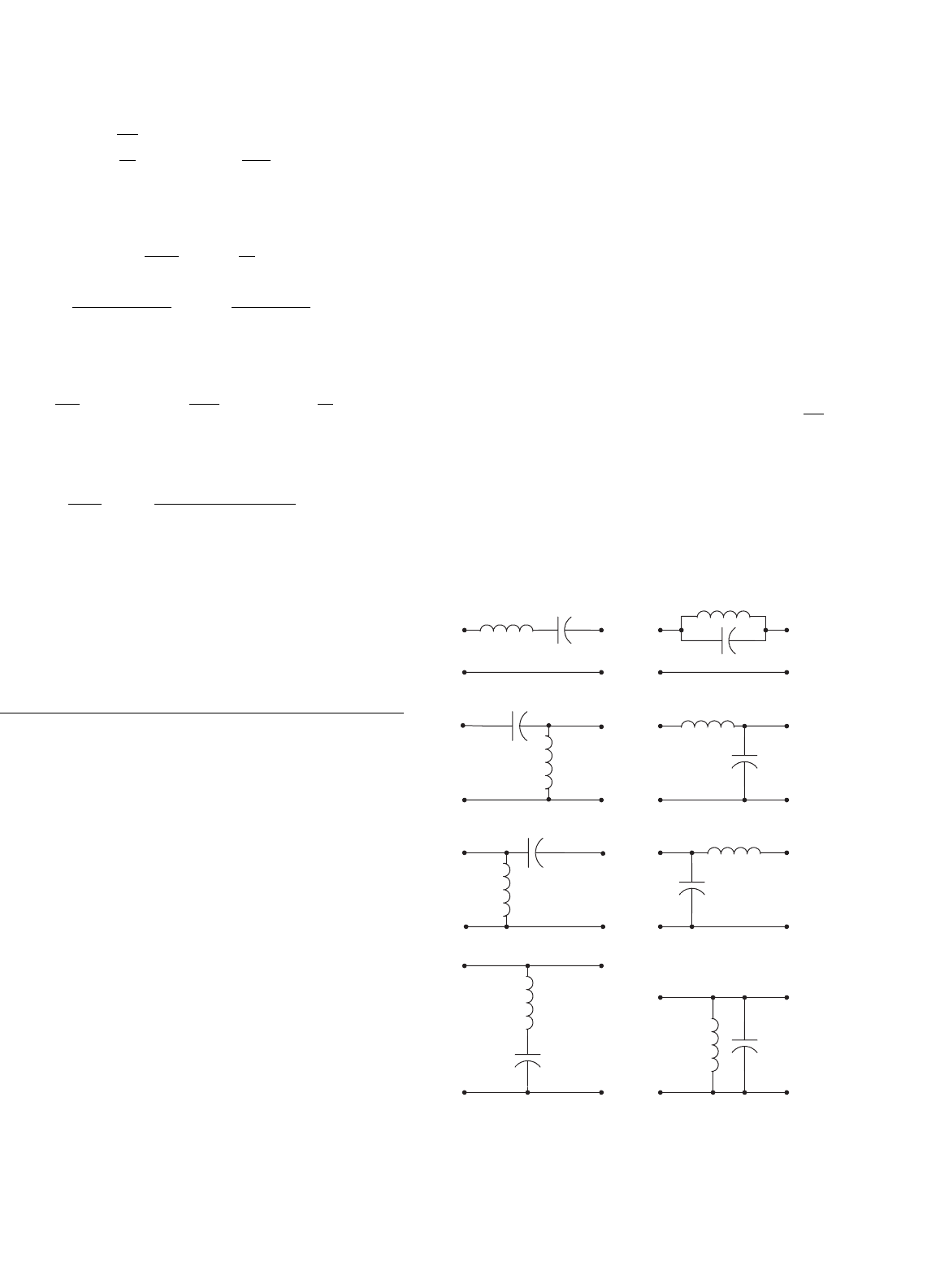
14.14.1 Two Energy-storage Elements Resonant
Power Converters
The 8 topologies of 2-element RPC are shown in Fig. 14.108.
These topologies have simple circuit structure and least com-
ponents. Consequently, they can transfer the power from
source to end-users with higher power efficiency and lower
power losses.
Usually, the 2-Element RPC has very narrow response fre-
quency bands, which is defined as the frequency width between
the two half-power points. The working point must be selected
in the vicinity of the natural resonant frequency ω
0
= 1/
√
LC.
Another drawback is that the transferred waveform is usu-
ally not a perfect sinusoidal, i.e. the output waveform THD is
not zero.
Since total power losses are mainly contributed by the
power losses across the main switches. As resonant conversion
technique, the 2-Element RPC has high power transferring
efficiency.
(1)
(3)
(5)
(7)
(2)
(4)
(6)
(8)
FIGURE 14.108 8 topologies of 2-element RPC.
336 F. L. Luo and H. Ye
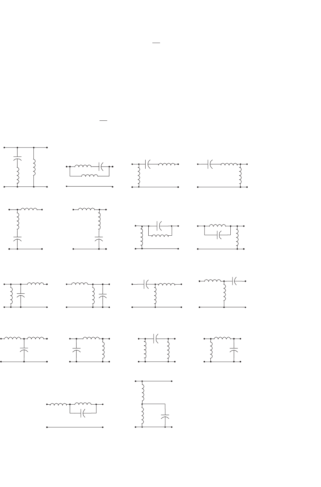
14.14.2 Three Energy-storage Elements
Resonant Power Converters
The 38 topologies of 3-element RPC are shown in Fig. 14.109.
These topologies have one more component when compared
to the 2-element RPC topologies. Consequently, they can
transfer the power from source to end-users with higher lower
power and lower power transfer efficiency.
Usually, the 3-element RPC has a much wider response
frequency bands, which is defined as the frequency width
between the two half-power points. If the circuit is a low-
pass filter, the frequency bands can cover the frequency range
from 0 to the natural resonant frequency ω
0
= 1/
√
LC. The
working point can be selected from a much wider frequency
(2)
(9)
(1)
(5)
(3) (4)
(6) (7) (8)
(10) (11) (12)
(13) (14) (15) (16)
(17) (18)
FIGURE 14.109 38 topologies of 3-element RPC.
width which is lower than the natural resonant frequency
ω
0
= 1/
√
LC.
Another advantage, better than the 2-element RPC topolo-
gies, is that the transferred waveform can usually be a
perfect sinusoidal, i.e. the output waveform THD is nearly
zero. As well-known, mono-frequency waveform transferring
operation has very low EMI.
14.14.3 Four Energy-storage Elements Resonant
Power Converters
The 98 topologies of 4-element (2L-2C) RPC are shown in
Fig. 14.110. If no restriction such as 2L-2C for 4-element RPC,
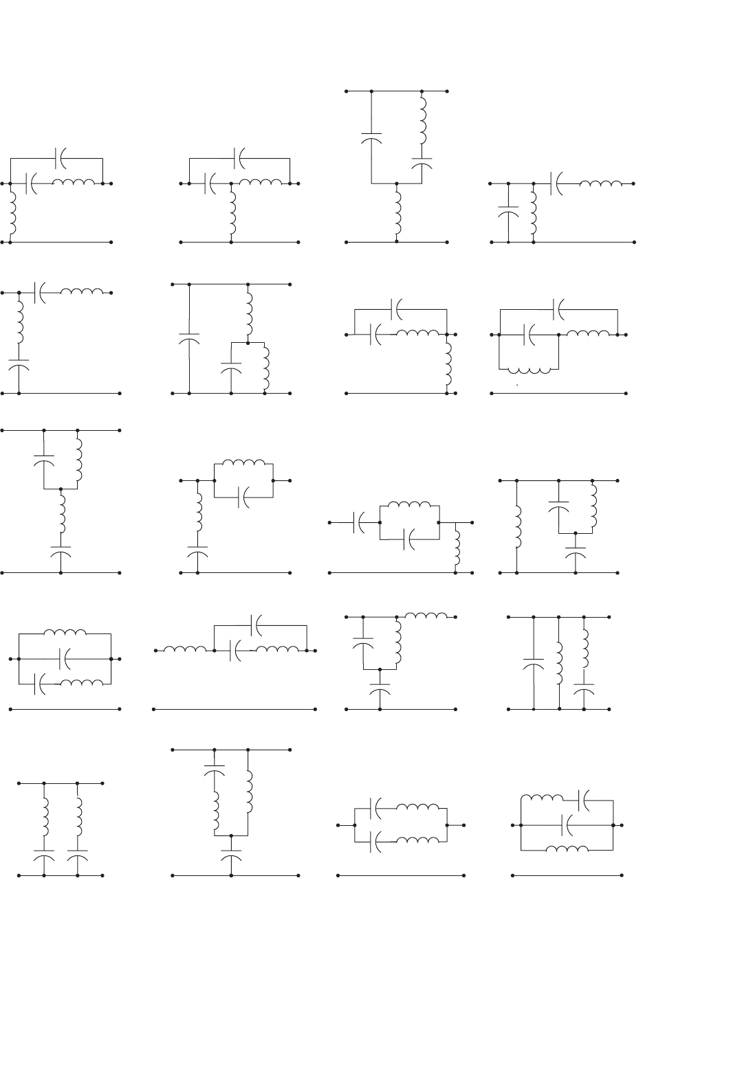
14 DC/DC Conversion Technique and 12 Series Luo-converters 337
(2)
(3) (4)
(5)
(6)
(1)
(7)
c
(8)
(12)(9)
(13) (15)
(11)(10)
(14) (16)
(17) (18) (19) (20)
FIGURE 14.110 98 topologies of 4-element RPC.