Power electronic handbook
Подождите немного. Документ загружается.

278 F. L. Luo and H. Ye
+
−
i
I
i
I
S
L
i
L
i
L
V
I
V
I
C
1
C
1
C
1
L
O
L
O
L
O
D
C
O
C
O
C
O
R
+
−
V
O
V
O
V
O
+
−
V
C1
V
C1
V
C1
i
LO
i
LO
i
O
i
O
D
1
+−
V
C
V
C
i
LO
i
O
V
C
C
L
1
L
1
D
2
D
11
D
10
i
L1
i
L1
i
L1
V
C2
V
C2
V
C2
+−
C
2
C
2
C
2
D
12
V
C3
V
C3
V
C3
+−
C
3
C
3
C
3
L
2
L
2
L
2
D
3
(a)
+
−
L
R
+
−
+
−
+
−
C
+−
+−
L
i
L
R
+
−
+
−
+−
C
L
1
i
L1
+−
+−
(b) (c)
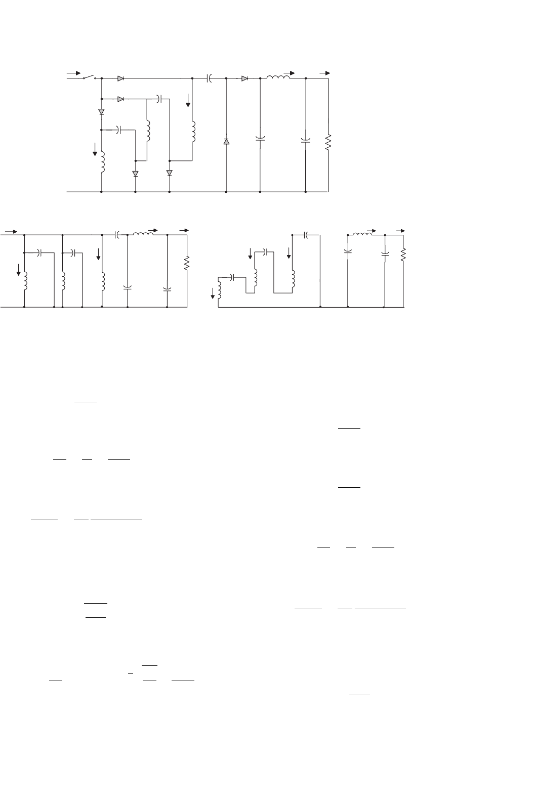
FIGURE 14.32 S P/O Luo-converter triple-lift circuit: (a) circuit diagram; (b) switch on; and (c) switch off.
and
I
O
=
1 −k
3
I
I
The voltage transfer gain in CCM is
M
T
=
V
O
V
I
=
I
I
I
O
=
3
1 −k
(14.65)
The variation ratio of the output voltage v
O
in CCM is
ε =
v
O
/2
V
O
=
k
128
1
f
3
L
O
C
1
C
O
R
(14.66)
This converter may work in discontinuous conduction
mode if the frequency f is small, conduction duty k is small,
inductance L is small, and load current is high. The condition
for DCM is
M
T
≤
3kz
N
2
(14.67)
The output voltage in DCM is
V
O
=
3 +k
2
(1 −k)
R
2fL
V
I
with
√
k
3R
2fL
≥
3
1 −k
(14.68)
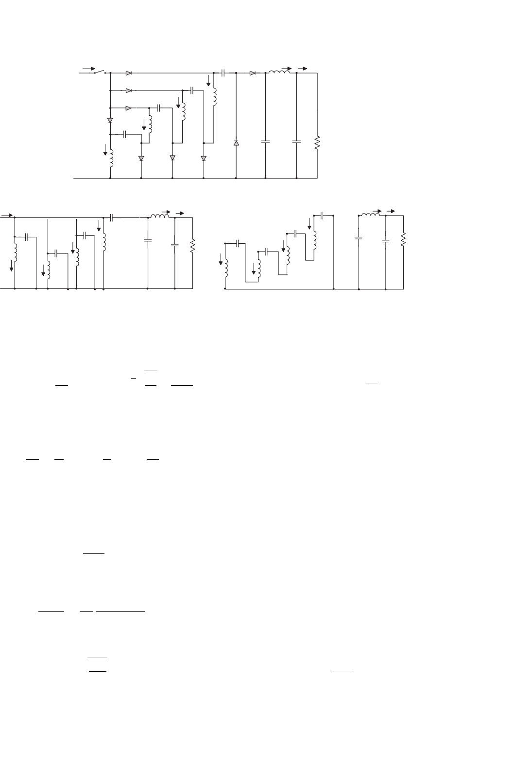
S P/O Luo quadruple-lift circuit is shown in Fig. 14.33a.
The equivalent circuits during switch-on and -off periods are
shown in Figs. 14.33b and c. Its output voltage and current are
V
O
=
4
1 −k
V
I
and
I
O
=
1 −k
4
I
I
The voltage transfer gain in CCM is
M
Q
=
V
O
V
I
=
I
I
I
O
=
4
1 −k
(14.69)
The variation ratio of the output voltage v
O
in CCM is
ε =
v
O
/2
V
O
=
k
128
1
f
3
L
O
C
1
C
O
R
(14.70)
This converter may work in discontinuous conduction
mode if the frequency f is small, conduction duty k is small,
inductance L is small, and load current is high. The condition
for DCM is
M
Q
≤
2kz
N
(14.71)
14 DC/DC Conversion Technique and 12 Series Luo-converters 279
+
−
i
I
i
I
S
L
L
L
i
L
i
L
i
L
V
I
V
I
C
1
C
1
C
1
L
O
L
O
L
O
D
R
+
−
V
O
V
O
V
O
+
−
V
C1
V
C1
V
C1
i
LO
i
LO
i
LO
i
O
i
O
i
O
D
1
+
−
V
C
V
C
C
C
C
L
1
L
1
L
1
D
2
D
11
D
10
i
L1
i
L1
i
L1
V
C2
V
C2
+−
C
2
C
2
C
2
D
12
V
C3
V
C3
+−
C
3
C
3
L
2
L
2
L
2
D
3
C
4
C
4
D
4
L
3
L
3
L
3
+
V
C4
V
C4
−
D
13
i
L2
i
L2
i
L3
i
L3
i
L3
C
O
C
O
C
O
(a)
+
−
R
R
+
−
+
−
+−
V
C
+−
+−
V
C2
+−
+
−
V
C3
C
3
i
L2
+
−
+−
C
4
V
C4
+−
+
−
+
−
(b) (c)
FIGURE 14.33 S P/O Luo-converter quadruple-lift circuit: (a) circuit diagram; (b) switch on; and (c) switch off.
The output voltage in DCM is
V
O
=
4 +k
2
(1 −k)
R
2fL
V
I
with
√
k
2R
fL
≥
4
1 −k
(14.72)
Summary for all S P/O Luo-converters:
M =
V
O
V
I
=
I
I
I
O
; z
N
=
R
fL
; R =
V
O
I
O
To write common formulas for all circuits parameters, we
define that subscript j = 1 for the self-lift circuit, j = 2 for
the re-lift circuit, j = 3 for the triple-lift circuit, j = 4 for the
quadruple-lift circuit, and so on. The voltage transfer gain is
M
j
=
j
1 −k
(14.73)
The variation ratio of the output voltage is
ε
j
=
v
O
/2
V
O
=
k
128
1
f
3
L
O
C
1
C
O
R
(14.74)
The condition for discontinuous mode is
M
j
≤
jkz
N
2
(14.75)
The output voltage in discontinuous mode is
V
O−j
=
j + k
2
(1 −k)
z
N
2
V
I
(14.76)
14.3.3 Negative Output Luo-converters
Negative output (N/O) Luo-converters perform the volt-
age conversion from positive to negative voltages using the
voltage-lift technique. They work in the third-quadrant with
large voltage amplification. Their voltage transfer gains are
high. Five circuits are introduced in the literature. They are:
• Elementary circuit;
• Self-lift circuit;
•
Re-lift circuit;
• Triple-lift circuit;
• Quadruple-lift circuit.
Further lift circuits can be derived from above circuits.
In all N/O Luo-converters, we define normalized impedance
z
N
= R/fL.
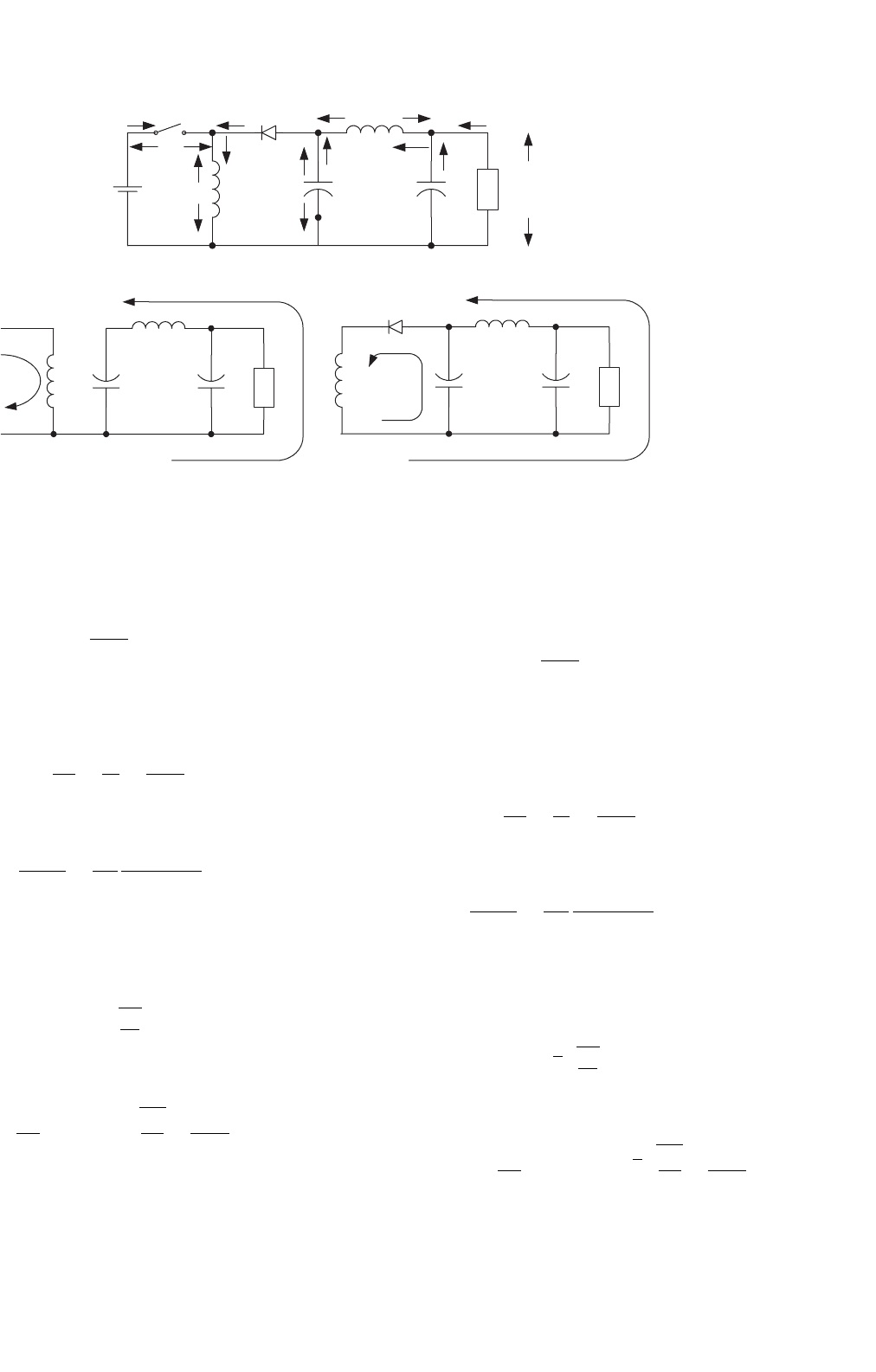
N/O Luo-converter elementary circuit is shown in
Fig. 14.34a. The equivalent circuits during switch-on and -off
periods are shown in Figs. 14.34b and c. Its output voltage and
current (the absolute value) are
V
O
=
k
1 −k
V
I
280 F. L. Luo and H. Ye
V
S
V
IN
i
I
+−
i
D
V
L
i
L
+
−
V
D
+
−
L
D
CC
O
i
C
+
−
+
V
C
−
L
O
i
LO
V
LO
i
CO
I
O
R
+
−
V
O
(a)
C
R
C
O
V
IN
+
−
L
L
O
L
C
R
C
O
L
O
D
(b) (c)
FIGURE 14.34 N/O Luo-converter elementary circuit: (a) circuit diagram; (b) switch on; and (c) switch off.
and
I
O
=
1 −k
k
I
I
When k is greater than 0.5, the output voltage can be higher
than the input voltage.
The voltage transfer gain in CCM is
M
E
=
V
O
V
I
=
I
I
I
O
=
k
1 −k
(14.77)
The variation ratio of the output voltage v
O
in CCM is
ε =
v
O
/2
V
O
=
k
128
1
f
3
CC
O
L
O
R
(14.78)
This converter may work in discontinuous conduction
mode if the frequency f is small, conduction duty k is small,
inductance L is small, and load current is high. The condition
for DCM is
M
E
≤ k
z
N
2
(14.79)
The output voltage in DCM is
V
O
= k(1 − k)
R
2fL
V
I
with
R
2fL
≥
1
1 −k
(14.80)
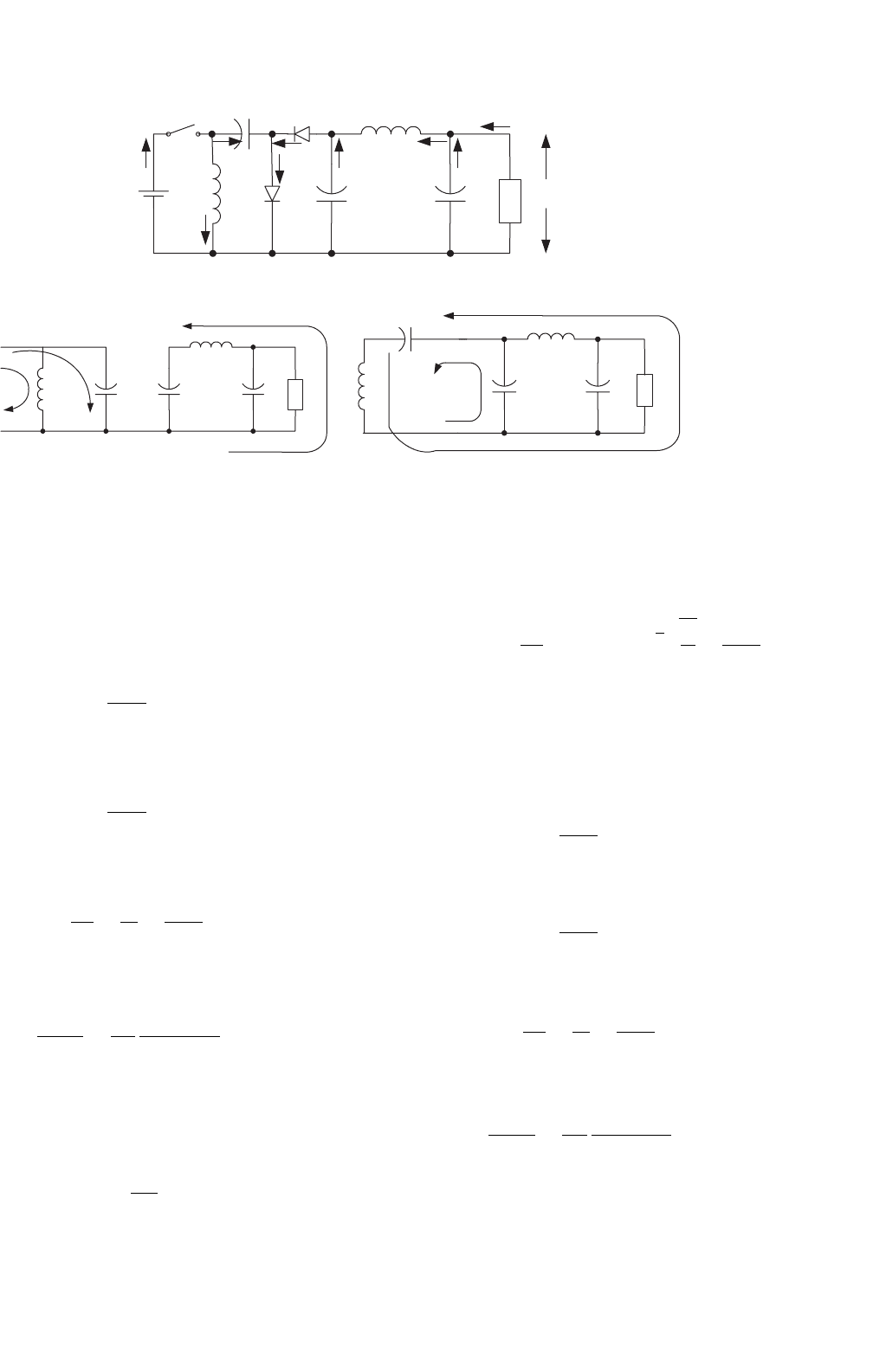
N/O Luo-converter self-lift circuit is shown in Fig. 14.35a.
The equivalent circuits during switch-on and -off periods are
shown in Figs. 14.35b and c. Its output voltage and current
(the absolute value) are
V
O
=
1
1 −k
V
I
and
I
O
= (1 −k)I
I
The voltage transfer gain in CCM is
M
S
=
V
O
V
I
=
I
I
I
O
=
1
1 −k
(14.81)
The variation ratio of the output voltage v
O
in CCM is
ε =
v
O
/2
V
O
=
k
128
1
f
3
CC
O
L
O
R
(14.82)
This converter may work in discontinuous conduction
mode if the frequency f is small, conduction duty k is small,
inductance L is small, and load current is high. The condition
for DCM is
M
S
≤
√
k
z
N
2
(14.83)
The output voltage in DCM is
V
O
=
1 +k
2
(1 −k)
R
2fL
V
I
with
√
k
R
2fL
≥
1
1 −k
(14.84)
14 DC/DC Conversion Technique and 12 Series Luo-converters 281
C
+
−
L
V
C
V
O
L
O
V
D1
C
1
V
IN
+
−
D
+−
V
LO
−+
+
−
i
O
i
CO
i
LO
i
C
i
D
i
D1
V
C1
+−
V
D
S
i
IN
i
L
i
C1
C
O
R
(a)
L
L
O
+
−
CC
1
RC
O
L
L
O
C
C
O
R
C
1
(b) (c)
FIGURE 14.35 N/O Luo-converter self-lift circuit: (a) circuit diagram; (b) switch on; and (c) switch off.
N/O Luo-converter re-lift circuit is shown in Fig. 14.36a.
The equivalent circuits during switch-on and -off periods are
shown in Figs. 14.36b and c. Its output voltage and current
(the absolute value) are
V
O
=
2
1 −k
V
I
and
I
O
=
1 −k
2
I
I
The voltage transfer gain in CCM is
M
R
=
V
O
V
I
=
I
I
I
O
=
2
1 −k
(14.85)
The variation ratio of the output voltage v
O
in CCM is
ε =
v
O
/2
V
O
=
k
128
1
f
3
CC
O
L
O
R
(14.86)
This converter may work in discontinuous conduction
mode if the frequency f is small, conduction duty k is small,
inductance L is small, and load current is high. The condition
for DCM is
M
R
≤
kz
N
(14.87)
The output voltage in DCM is
V
O
=
2 +k
2
(1 −k)
R
2fL
V
I
with
√
k
R
fL
≥
2
1 −k
(14.88)
N/O Luo-converter triple-lift circuit is shown in
Fig. 14.37a. The equivalent circuits during switch-on and -off
periods are shown in Figs. 14.37b and c. Its output voltage and
current (the absolute value) are
V
O
=
3
1 −k
V
I
and
I
O
=
1 −k
3
I
I
The voltage transfer gain in CCM is
M
T
=
V
O
V
I
=
I
I
I
O
=
3
1 −k
(14.89)
The variation ratio of the output voltage v
O
in CCM is
ε =
v
O
/2
V
O
=
k
128
1
f
3
CC
O
L
O
R
(14.90)
This converter may work in discontinuous conduction
mode if the frequency f is small, conduction duty k is small,

282 F. L. Luo and H. Ye
L
O
C
1
D
V
LO
−+
i
O
i
CO
i
LO
i
C
i
C1
V
S
+
−
S
i
IN
L
C
2
C
V
O
+
−
C
O
R
D
1
V
IN
i
L
D
2
D
10
D
11
i
D11
i
L1
L
1
i
D
(a)
L
O
C
RC
O
LV
IN
+
−
C
1
L
1
C
2
L
O
C
C
O
R
L
C
1
C
2
L
1
(b) (c)
FIGURE 14.36 N/O Luo-converter re-lift circuit: (a) circuit diagram; (b) switch on; and (c) switch off.
L
O
L
O
L
O
D
V
LO
−+
V
LO
−+
V
LO
−+
i
O
i
O
i
O
i
CO
i
CO
i
CO
i
LO
i
LO
i
LO
i
C
i
C
i
C
C
C
C
V
O
+
−
V
O
+
−
V
O
+
−
C
O
C
O
C
O
R
R
R
D
1
D
2
i
D1
i
L1
i
L1
i
L1
L
1
L
1
L
1
i
D
C
2
C
2
C
2
i
D2
V
S
+
−
S
i
IN
i
IN
L
L
L
C
3
C
3
C
3
V
IN
V
IN
i
L
i
L
i
L
D
10
D
12
D
11
L
2
L
2
L
2
i
L2
i
L2
i
L2
i
C2
i
C2
D
3
i
D3
C
1
C
1
C
1
i
C1
i
C1
(a)
(b) (c)
FIGURE 14.37 N/O Luo-converter triple-lift circuit: (a) circuit diagram; (b) switch on; and (c) switch off.

14 DC/DC Conversion Technique and 12 Series Luo-converters 283
inductance L is small, and load current is high. The condition
for DCM is
M
T
≤
3kz
N
2
(14.91)
The output voltage in DCM is
V
O
=
3 +k
2
(1 −k)
R
2fL
V
I
with
√
k
3R
2fL
≥
3
1 −k
(14.92)
N/O Luo-converter quadruple-lift circuit is shown in
Fig. 14.38a. The equivalent circuits during switch-on and -off
periods are shown in Figs. 14.38b and c. Its output voltage and
current (the absolute value) are
V
O
=
4
1 −k
V
I
and
I
O
=
1 −k
4
I
I
L
O
L
O
L
O
C
1
C
1
C
1
D
V
LO
−+
V
LO
−+
V
LO
−+
i
O
i
O
i
O
i
CO
i
CO
i
CO
i
LO
i
LO
i
LO
i
C
i
C
i
C
i
C1
i
C1
C
C
C
V
O
+
−
V
O
+
−
V
O
+
−
C
O
C
O
C
O
R
R
R
D
1
D
2
i
D1
i
L1
i
L1
i
L1
L
1
L
1
L
1
i
D
C
2
C
2
C
2
i
D2
V
S
+−
S
i
IN
L
L
L
C
4
C
4
C
4
V
IN
i
IN
V
IN
i
L
i
L
i
L
D
10
D
13
D
11
L
3
L
3
L
3
i
L2
i
L2
i
L2
i
C2
i
C2
D
4
i
D4
D
12
D
3
L
2
L
2
L
2
i
L3
i
L3
i
L3
C
3
C
3
C
3
i
D3
i
D11
i
D12
i
C3
i
C3
i
D13
i
C4
(a)
(b) (c)
FIGURE 14.38 N/O Luo-converter quadruple-lift circuit: (a) circuit diagram; (b) switch on; and (c) switch off.
The voltage transfer gain in CCM is
M
Q
=
V
O
V
I
=
I
I
I
O
=
4
1 −k
(14.93)
The variation ratio of the output voltage v
O
in CCM is
ε =
v
O
/2
V
O
=
k
128
1
f
3
CC
O
L
O
R
(14.94)
This converter may work in discontinuous conduction
mode if the frequency f is small, conduction duty k is small,
inductance L is small, and load current is high. The condition
for DCM is
M
Q
≤
2kz
N
(14.95)
The output voltage in DCM is
V
O
=
4 +k
2
(1 −k)
R
2fL
V
I
with
√
k
2R
fL
≥
4
1 −k
(14.96)

284 F. L. Luo and H. Ye
Summary for all N/O Luo-converters:
M =
V
O
V
I
=
I
I
I
O
; z
N
=
R
fL
; R =
V
O
I
O
To write common formulas for all circuits parameters, we
define that subscript j = 0 for the elementary circuit, j = 1
for the self-lift circuit, j = 2 for the re-lift circuit, j = 3 for
the triple-lift circuit, j = 4 for the quadruple-lift circuit, and
so on. The voltage transfer gain is
M
j
=
k
h(j)
[j + h(j)]
1 −k
(14.97)
The variation ratio of the output voltage is
ε =
v
O
/2
V
O
=
k
128
1
f
3
CC
O
L
O
R
(14.98)
The condition for discontinuous conduction mode is
k
[1+h(j)]
M
2
j
j + h(j)
2
z
N
≥ 1 (14.99)
The output voltage in discontinuous conduction mode is
V
O−j
=
j + k
[2−h(j)]
1 −k
2
z
N
V
I
(14.100)
where
h(j) =
0 if j ≥ 1
1 if j = 0
is the Hong function.
14.4 Double Output Luo-converters
Double output (D/O) Luo-converters perform the voltage
conversion from positive to positive and negative voltages
simultaneously using the voltage-lift technique. They work in
the first- and third-quadrants with high voltage transfer gain.
There are five circuits introduced in this section:
• D/O Luo-converter elementary circuit;
• D/O Luo-converter self-lift circuit;
• D/O Luo-converter re-lift circuit;
• D/O Luo-converter triple-lift circuit;
• D/O Luo-converter quadruple-lift circuit.
Further lift circuits can be derived from above circuits.
In all D/O Luo-converters, each circuit has two conver-
sion paths – positive conversion path and negative conversion
path. The positive path likes P/O Luo-converters, and the
negative path likes N/O Luo-converters. We define normal-
ized impedance z
N +
=R/fL for positive path, and normalized
impedance z
N −
=R
1
/fL
11
. We usually purposely select R = R
1
and L = L
11
, so that we have z
N
= z
N +
= z
N −
.
D/O Luo-converter elementary circuit is shown in
Fig. 14.7. Its output voltages and currents (absolute values)
are
V
O+
=|V
O−
|=
k
1 −k
V
I
I
O+
=
1 −k
k
I
I+
and
I
O−
=
1 −k
k
I
I−
When k is greater than 0.5, the output voltage can be higher
than the input voltage.
The voltage transfer gain in CCM is
M
E
=
V
O+
V
I
=
|V
O−
|
V
I
=
k
1 −k
(14.101)
The variation ratio of the output voltage v
O+
in CCM is
ε
+
=
v
O+
/2
V
O+
=
k
16M
E
1
f
2
C
O
L
2
(14.102)
The variation ratio of the output voltage v
O−
in CCM is
ε
−
=
v
O−
/2
V
O−
=
k
128
1
f
3
C
11
C
10
L
12
R
1
(14.103)
This converter may work in discontinuous conduction
mode if the frequency f is small, conduction duty k is small,
inductance L is small, and load current is high. The condition
for DCM is
M
E
≤ k
z
N
2
(14.104)
The output voltages in DCM are
V
O
= V
O+
=|V
O−
|=k(1 − k)
z
N
2
V
I
with
z
N
2
≥
1
1 −k
(14.105)
14 DC/DC Conversion Technique and 12 Series Luo-converters 285
V
C1
D
0
C
1
+−
−
+
V
C11
D
10
i
L2
L
2
L
12
i
L2
D
1
C
2
C
11
C
12
L
1
i
L11
L
11
i
L1
D
21
D
20
i
IN
+
i
IN
−
V
S
S
i
IN
−
V
IN
+
D
11
I
o
+
C
o
+
−
V
o
+
R
C
10
+
−
I
o
−
V
o
−
R
1
FIGURE 14.39 Double output Luo-converter self-lift circuit.
D/O Luo-converter self-lift circuit is shown in Fig. 14.39.
Its output voltages and currents (absolute values) are
V
O+
=|V
O−
|=
1
1 −k
V
I
I
O+
= (1 −k)I
I+
and
I
O−
= (1 −k)I
I−
The voltage transfer gain in CCM is
M
S
=
V
O+
V
I
=
|V
O−
|
V
I
=
1
1 −k
(14.106)
The variation ratio of the output voltage v
O+
in CCM is
ε
+
=
v
O+
/2
V
O+
=
k
128
1
f
3
L
2
C
O
C
2
R
(14.107)
The variation ratio of the output voltage v
O−
in CCM is
ε
−
=
v
O−
/2
V
O−
=
k
128
1
f
3
C
11
C
10
L
12
R
1
(14.108)
This converter may work in discontinuous conduction
mode if the frequency f is small, conduction duty k is small,
inductance L is small, and load current is high. The condition
for DCM is
M
S
≤
√
k
z
N
2
(14.109)
The output voltages in DCM are
V
O
= V
O+
=|V
O−
|=
1 +k
2
(1 −k)
z
N
2
V
I
with
kz
N
2
≥
1
1 −k
(14.110)
D/O Luo-converter re-lift circuit is shown in Fig. 14.40. Its
output voltages and currents (absolute values) are
V
O+
=|V
O−
|=
2
1 −k
V
I
I
O+
=
1 −k
2
I
I+
and
I
O−
=
1 −k
2
I
I−
The voltage transfer gain in CCM is
M
R
=
V
O+
V
I
=
|V
O−
|
V
I
=
2
1 −k
(14.111)
The variation ratio of the output voltage v
O+
in CCM is
ε
+
=
v
O+
/2
V
O+
=
k
128
1
f
3
L
2
C
O
C
2
R
(14.112)
The variation ratio of the output voltage v
O−
in CCM is
ε
−
=
v
O−
/2
V
O−
=
k
128
1
f
3
C
11
C
10
L
12
R
1
(14.113)
This converter may work in discontinuous conduction
mode if the frequency f is small, conduction duty k is small,
286 F. L. Luo and H. Ye
C
1
V
C1
+
i
L2
L
2
D
1
I
O
+
+
D
0
C
2
L
1
C
0
−
V
O
+
R
−
i
IN
C
3
i
IN
+
V
S
S
i
L1
−
V
IN
+
L
3
D
20
D
2
D
3
V
C11
i
L12
L
12
D
10
I
O
−
+
D
12
C
11
L
11
C
10
−
V
O
−R
1
−
i
IN
−
i
L11
L
13
D
21
D
22
D
11
C
13
C
12
+
FIGURE 14.40 D/O Luo-converter re-lift circuit.
inductance L is small, and load current is high. The condition
for DCM is
M
R
≤
kz
N
(14.114)
The output voltages in DCM are
V
O
= V
O+
=|V
O−
|=
2 +k
2
(1 −k)
z
N
2
V
I
with
kz
N
≥
2
1 −k
(14.115)
C
1
V
C1
+
i
L2
L
2
D
1
I
O
+
+
D
0
C
2
C
0
−
V
O
+
R
L
3
D
3
V
C11
+
−
i
L12
L
12
D
10
I
O
−
+
D
13
C
11
C
10
−
V
O
−
R
1
L
13
D
11
C
14
L
1
−
i
IN
C
3
i
IN
+
V
S
S
i
L1
−
V
IN
+
D
20
D
2
L
11
i
IN
−
i
L11
D
21
D
22
C
12
C
4
L
4
D
5
D
4
D
12
C
13
D
23
L
14
FIGURE 14.41 D/O Luo-converter triple-lift circuit.
D/O Luo-converter triple-lift circuit is shown in Fig. 14.41.
Its output voltages and currents (absolute values) are
V
O+
=|V
O−
|=
3
1 −k
V
I
I
O+
=
1 −k
3
I
I+
and
I
O−
=
1 −k
3
I
I−
14 DC/DC Conversion Technique and 12 Series Luo-converters 287
C
1
V
C1
+
i
L2
L
2
D
1
I
o
+
+
D
0
C
2
C
o
−
V
o
+
R
V
C11
+
i
L12
L
12
D
10
I
o
−
+
C
11
C
10
−
V
o
−
R
1
−
C
14
L
5
D
5
L
3
D
3
L
13
D
11
L
1
−
i
IN
C
3
i
IN
+
V
S
S
i
L1
−
V
IN
+
D
4
D
2
L
11
i
IN
−
i
L11
D
21
D
22
C
12
C
4
D
6
C
13
D
23
C
5
D
20
L
4
D
7
D
12
D
13
D
24
C
15
D
14
FIGURE 14.42 D/O Luo-converter quadruple-lift circuit.
The voltage transfer gain in CCM is
M
T
=
V
O+
V
I
=
|V
O−
|
V
I
=
3
1 −k
(14.116)
The variation ratio of the output voltage v
O+
in CCM is
ε
+
=
v
O+
/2
V
O+
=
k
128
1
f
3
L
2
C
O
C
2
R
(14.117)
The variation ratio of the output voltage v
O−
in CCM is
ε
−
=
v
O−
/2
V
O−
=
k
128
1
f
3
C
11
C
10
L
12
R
1
(14.118)
This converter may work in discontinuous conduction
mode if the frequency f is small, conduction duty k is small,
inductance L is small, and load current is high. The condition
for DCM is
M
T
≤
3kz
N
2
(14.119)
The output voltages in DCM are
V
O
= V
O+
=|V
O−
|=
3 +k
2
(1 −k)
z
N
2
V
I
with
3kz
N
2
≥
3
1 −k
(14.120)
D/O Luo-converter quadruple-lift circuit is shown in
Fig. 14.42. Its output voltages (absolute values) are
V
O+
=|V
O−
|=
4
1 −k
V
I
I
O+
=
1 −k
4
I
I+
and
I
O−
=
1 −k
4
I
I−
The voltage transfer gain in CCM is
M
Q
=
V
O+
V
I
=
|V
O−
|
V
I
=
4
1 −k
(14.121)
The variation ratio of the output voltage v
O+
in CCM is
ε
+
=
v
O+
/2
V
O+
=
k
128
1
f
3
L
2
C
O
C
2
R
(14.122)
The variation ratio of the output voltage v
O−
in CCM is
ε
−
=
v
O−
/2
V
O−
=
k
128
1
f
3
C
11
C
10
L
12
R
1
(14.123)
This converter may work in discontinuous conduction
mode if the frequency f is small, conduction duty k is small,