Power electronic handbook
Подождите немного. Документ загружается.

268 F. L. Luo and H. Ye
C
L
R
V
o
+
−
1:1:N
T
1
+
D
1
D
2
D
3
V
in
−
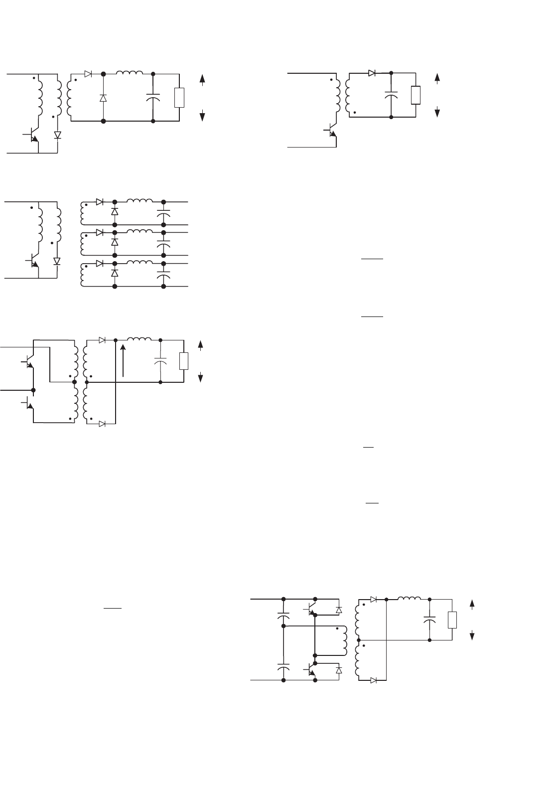
FIGURE 14.11 Forward converter with tertiary winding.
1:1:N
1
T
1
+
−
V
in
O/P 1
O/P 2
O/P 3
N
2
N
3
FIGURE 14.12 Forward converter with multiple secondary windings.
C
L
R
V
O
+
−
1:N
+
−
D
1
D
2
T
1
T
2
V'
+
−
V
I
FIGURE 14.13 Push–pull converter.
Push–pull converter is a step-up/down converter, which
is shown in Fig. 14.13. It is not necessary to set the tertiary
winding. The transformer turns ratio is N (usually N > 1).
If the transformer has never been saturated during operation,
it works as a buck converter with the conduction duty cycle
k < 0.5. The output voltage and current are
V
O
= 2kNV
I
(14.13)
and
I
O
=
1
2kN
I
I
(14.14)
This converter may work in discontinuous mode if the fre-
quency f is small, conduction duty k is small, inductance L is
small, and load current is high.
Fly-back converter is a high step-up converter, which is
shown in Fig. 14.14. The transformer turns ratio is N (usually
N > 1). It effectively uses the transformer leakage inductance
CR
+
−
1:N
T
1
Control
+
−
D
1
V
I
V
O
FIGURE 14.14 Fly-back converter.
in fly-back operation to obtain high surge voltage induced,
then get high output voltage. It works likely in buck–boost
operation as a buck–boost converter. Its output voltage and
current are
V
O
=
kN
1 −k
V
I
(14.15)
and
I
O
=
1 −k
kN
I
I
(14.16)
Half-bridge converter is a step-up converter, which is
shown in Fig. 14.15. There are two switches and one double
secondary coils transformer required. The transformer turns
ratio is N. It works as a half-bridge rectifier (half of V
1
inputs
to primary winding) plus a buck converter circuit in secondary
side. The conduction duty cycle k is set in 0.1 < k < 0.5. Its
output voltage and current are
V
O
= 2kN
V
I
2
= kNV
I
(14.17)
and
I
O
=
1
kN
I
I
(14.18)
This converter may work in discontinuous mode if the fre-
quency f is small, conduction duty k is small, inductance L is
small, and load current is high.
C
3
L
RV
O
+
−
D
1
D
2
C
1
C
2
T
1
T
2
+
−
V
in
1:N
FIGURE 14.15 Half-bridge converter.
14 DC/DC Conversion Technique and 12 Series Luo-converters 269
C
1
L
R
V
O
+
−
D
1
D
2
T
1
T
2
+
−
V
in
1:N
C
T
3
T
4
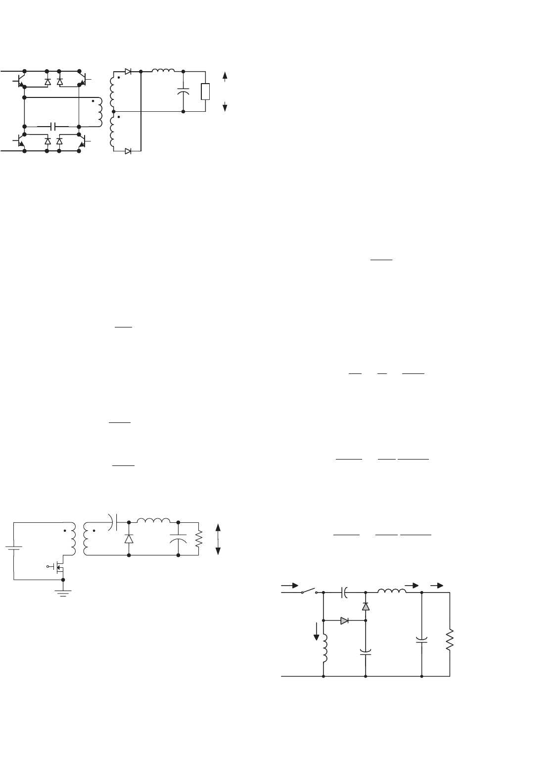
FIGURE 14.16 Bridge converter.
Bridge converter is a step-up converter, which is shown in
Fig. 14.16. There are four switches and one double secondary
coils transformer required. The transformer turns ratio is N.
It works as a full-bridge rectifier (full V
1
inputs to primary
winding) plus a buck-converter circuit in secondary side. The
conduction duty cycle k is set in 0.1 < k < 0.5. Its output
voltage and current are
V
O
= 2kNV
I
(14.19)
and
I
O
=
1
2kN
I
I
(14.20)
ZETA (zeta) converter is a step-up converter, which is
shown in Fig. 14.17. The transformer turns ratio is N. The
transformer functions as a inductor (L
1
) plus a buck–boost
converter plus a low-pass filter (L
2
–C
2
). Its output voltage
and current are
V
O
=
k
1 −k
NV
I
(14.21)
and
I
O
=
1 −k
kN
I
I
(14.22)
+
−
V
O
R
L
2
V
in
C
2
L
1
1:N
C
1
D
S
+
−
FIGURE 14.17 ZETA (zeta) converter.
14.2.4 Seven (7) Self-lift DC/DC Converters
Because of the effect of the parasitic elements, the voltage
conversion gain is limited. Especially, when the conduction
duty k is towards unity, the output voltage is sharply reduced.
Voltage-lift technique is a popular method used in electronic
circuit design. Applying this technique can effectively over-
come the effect of the parasitic elements, and largely increase
the voltage transfer gain. In this section, we introduce seven
self-lift converters which are working in continuous mode.
• Positive output (P/O) self-lift Luo-converter;
• Reverse P/O self-lift Luo-converter;
• Negative output (N/O) self-lift Luo-converter;
• Reverse N/O self-lift Luo-converter;
• Self-lift Cúk-converter;
• Self-lift SEPIC;
• Enhanced self-lift Luo-converter.
All self-lift converters (except enhanced self-lift circuit) have
the output voltage and current to be
V
O
=
1
1 −k
V
I
(14.23)
and
I
O
= (1 −k)I
I
(14.24)
The voltage transfer gain in continuous mode is
M
S
=
V
O
V
I
=
I
I
I
O
=
1
1 −k
(14.25)
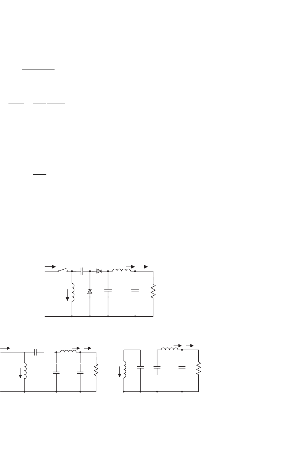
P/O self-lift Luo-converter is shown in Fig. 14.18. The vari-
ation ratio of the output voltage v
O
in continuous conduction
mode (CCM) is
ε =
v
O
/2
V
O
=
k
8M
S
1
f
2
C
O
L
2
(14.26)
Reverse P/O self-lift Luo-converter is shown in Fig. 14.19.
The variation ratio of the output voltage v
O
in CCM is
ε =
v
O
/2
V
O
=
k
16M
S
1
f
2
C
O
L
2
(14.27)
+
−
i
I
S
L
i
L
V
I
C
L
O
D
C
O
R
+
−
V
O
+
−
v
C
i
LO
i
O
D
1
C
1
+−
v
C1
FIGURE 14.18 P/O self-lift Luo-converter.
270 F. L. Luo and H. Ye
+
−
i
I
S
L
i
L
V
I
C
L
O
D
C
O
R
+
−
V
O
+
−
v
C
i
LO
i
O
D
1
C
1
+−
v
C1
FIGURE 14.19 Reverse P/O self-lift Luo-converter.
+
−
i
I
S
L
i
L
V
I
C
L
O
D
C
O
R
+
−
V
O
+
−
v
C
i
LO
i
O
D
1
C
1
+
−
v
C1
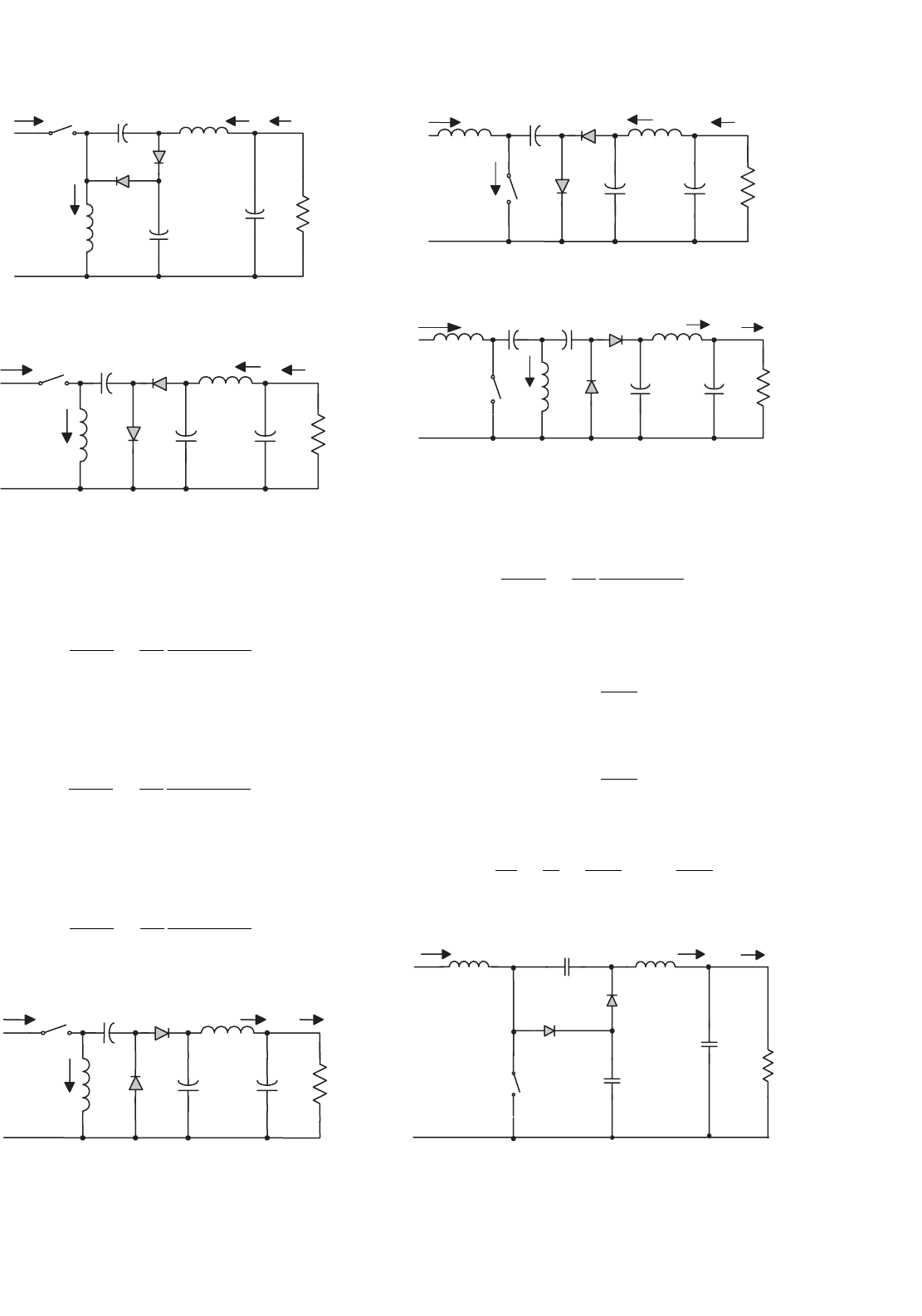
FIGURE 14.20 N/O self-lift Luo-converter.
N/O self-lift Luo-converter is shown in Fig. 14.20. The
variation ratio of the output voltage v
O
in CCM is
ε =
v
O
/2
V
O
=
k
128
1
f
3
L
O
C
1
C
O
R
(14.28a)
Reverse N/O self-lift Luo-converter is shown in Fig. 14.21.
The variation ratio of the output voltage v
O
in CCM is
ε =
v
O
/2
V
O
=
k
128
1
f
3
L
O
C
1
C
O
R
(14.28b)
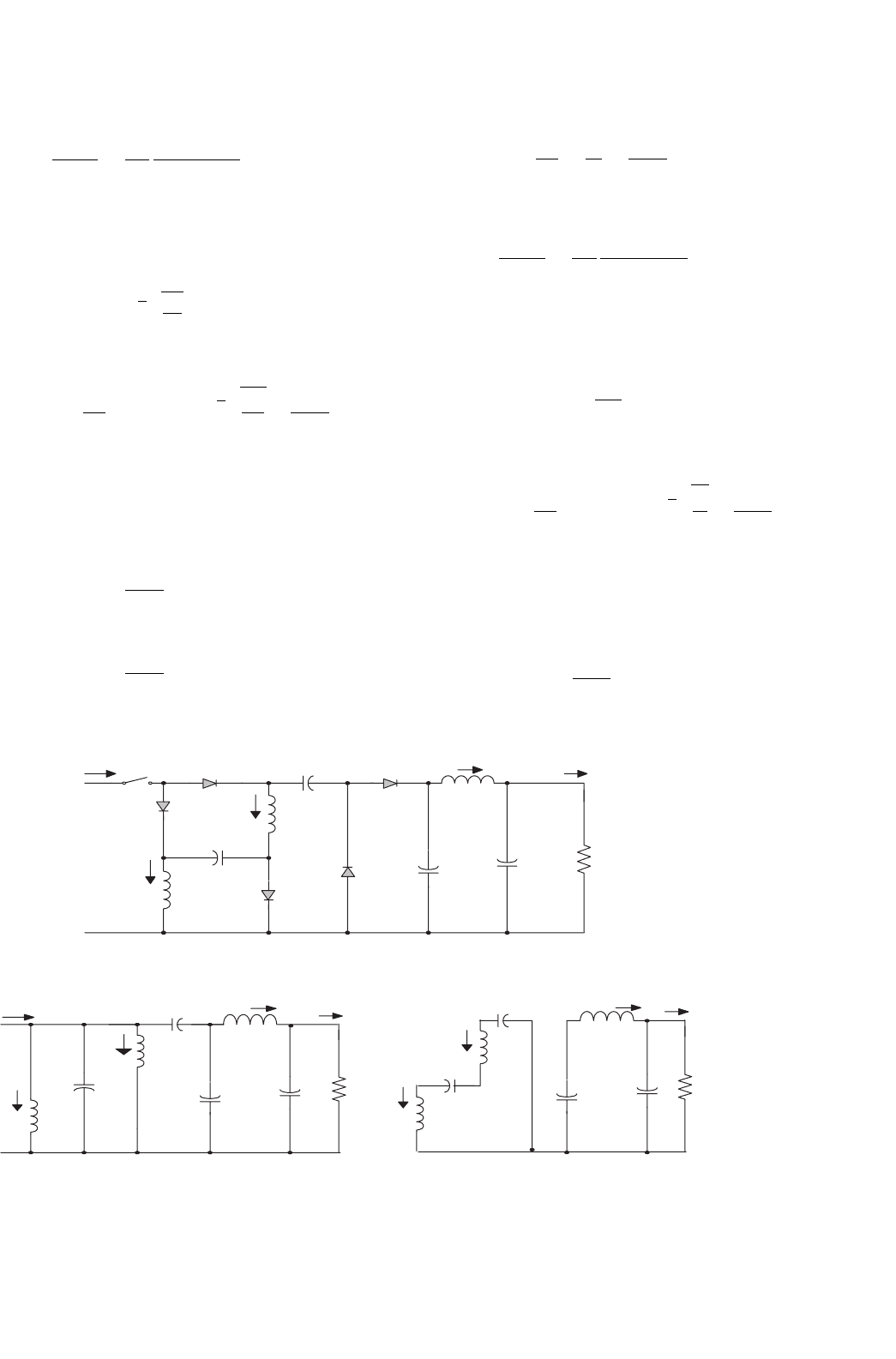
Self-lift Cúk-converter is shown in Fig. 14.22. The variation
ratio of the output voltage v
O
in CCM is
ε =
v
O
/2
V
O
=
k
128
1
f
3
L
O
C
1
C
O
R
(14.28c)
+
−
i
I
S
L
i
L
V
I
C
1
L
O
D
1
C
O
R
+
−
V
O
+
−
v
C1
i
LO
i
O
D
C
+−
v
C
FIGURE 14.21 Reverse N/O self-lift Luo-converter.
i
LO
+
−
i
I
S
L
V
I
C
L
O
D
C
O
R
+
−
+
−
v
C
i
O
D
1
C
1
+−
v
C1
V
O
FIGURE 14.22 Self-lift Cúk-converter.
i
LO
+
−
i
I
S
L
V
I
C
L
O
D
C
O
R
+
−
V
O
+
−
v
C1
i
O
D
1
C
2
+−
v
C2
+−
v
C
L
1
i
L1
FIGURE 14.23 Self-lift SEPIC.
Self-lift SEPIC is shown in Fig. 14.23. The variation ratio of
the output voltage v
O
in CCM is
ε =
v
O
/2
V
O
=
k
128
1
f
3
L
O
C
1
C
O
R
(14.28d)
Enhanced self-lift Luo-converter is shown in Fig. 14.24. Its
output voltage and current are
V
O
=
2 −k
1 −k
V
I
(14.29)
and
I
O
=
1 −k
2 −k
I
I
(14.30)
The voltage transfer gain in continuous mode is
M
S
=
V
O
V
I
=
I
I
I
O
=
1
1 −k
+1 =
2 −k
1 −k
(14.31)
C
−
v
C1
+
i
LO
L
O
+
−
V
O
R
C
O
D
+
−
V
I
L
D
1
C
1
+
−
v
C
i
I
i
O
S
FIGURE 14.24 Enhanced self-lift Luo-converter.
14 DC/DC Conversion Technique and 12 Series Luo-converters 271
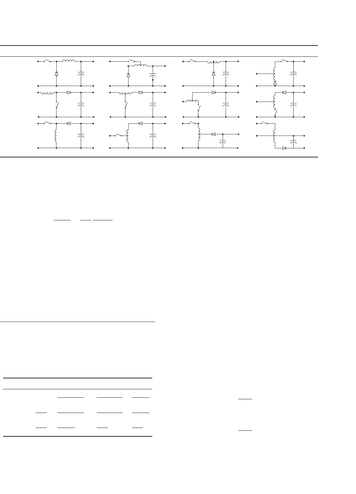
TABLE 14.1 The circuit diagrams of the tapped inductor fundamental converters
Standard converter Switch tap Diode to tap Rail to tap
Buck
C
L
V
IN
V
O
D
S
V
O
V
IN
C
N2
D
S
N1
V
O
V
IN
C
N1
D
S
N2
V
O
V
IN
C
N1
D
S
N2
Boost
V
IN
V
O
C
L
D
S
V
O
V
IN
C
N1
D
S
N2
V
O
V
IN
C
N1
D
S
N2
V
O
V
IN
C
N1
D
S
N2
Buck–Boost
V
IN
V
O
CL
D
S
V
O
V
IN
C
N2
D
S
N1
V
O
V
IN
C
N1
D
S
N2
V
O
V
IN
C
N1
D
S
N2
The variation ratio of the output voltage v
O
in CCM is as
in Eq. (14.26)
ε =
v
O
/2
V
O
=
k
8M
S
1
f
2
C
O
L
2
14.2.5 Tapped Inductor (Watkins–Johnson)
Converters
Tapped inductor (Watkins–Johnson) converters have been
derived from fundamental converters, which circuit diagrams
are shown in Table 14.1. The voltage transfer gains are shown
in Table 14.2. Here the tapped inductor ratio is n = n1/
(n1 +n2).
14.3 Voltage-lift Luo-converters
Voltage-lift (VL) technique is very popular for electronic cir-
cuit design. Professor Luo and Dr. Ye have successfully applied
this technique in the design of DC/DC converters, and created
TABLE 14.2 The voltage transfer gains of the tapped inductor
fundamental converters
Converter No tap Switched to tap Diode to tap Rail to tap
Buck k
k
n +k(1 − n)
nk
1 +k(n −1)
k − n
k(1 −n)
Boost
1
1 −k
n +k(1 − n)
n(1 − k)
1 +k(n −1)
1 −k
n −k
n(1 − k)
Buck–Boost
k
1 −k
k
n(1 − k)
nk
1 −k
k
1 −k
a number of up-to-date converters. There are three series of
Luo-converters introduced in this section:
• Positive output Luo-converters;
• Simplified positive output Luo-converters;
• Negative output Luo-converters.
14.3.1 Positive Output Luo-converters
Positive output (P/O) Luo-converters perform the voltage
conversion from positive to positive voltages using the volt-
age lift technique. They work in the first-quadrant with large
voltage amplification. Their voltage transfer gains are high.
Five circuits are introduced in the literature. They are:
•
Elementary circuit;
• Self-lift circuit;
• Re-lift circuit;
• Triple-lift circuit;
• Quadruple-lift circuit.
Further lift circuits can be derived from the above circuits.
In all P/O Luo-Converters, we define normalized inductance
L = L
1
L
2
/(L
1
+L
2
) and normalized impedance z
N
= R/fL.
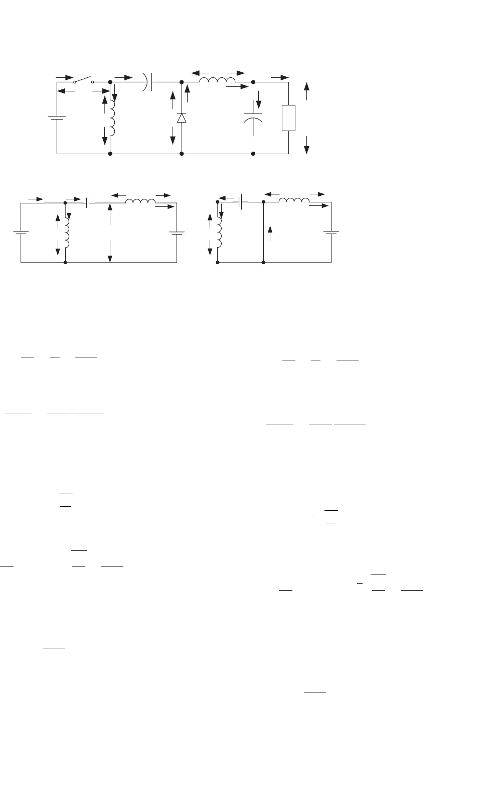
P/O Luo-converter elementary circuit is shown in
Fig. 14.25a. The equivalent circuits during switch-on and -off
periods are shown in Figs. 14.25b and c. Its output voltage and
current are
V
O
=
k
1 −k
V
I
and
I
O
=
1 −k
k
I
I
272 F. L. Luo and H. Ye
Vs
V
IN
i
IN
V
L1
+
+
−
−
C
i
C
i
L1
V
C
+−
L
1
D
i
D
+
−
+
V
D
−
L
2
i
L2
V
L2
C
o
+
−
i
Co
I
o
V
o
(a)
V
IN
i
IN
i
C
V
L1
i
L1
+
−
V
O
−
+
V
D
+−
L
2
i
L2
V
L2
i
C
i
L1
+
−
V
O
+
−
L
2
i
L2
V
L2
V
o
L
1
i
D
(b) (c)
R
FIGURE 14.25 P/O Luo-converter elementary circuit; (a) circuit diagram; (b) switch on; and (c) switch off.
The voltage transfer gain in continuous mode is
M
E
=
V
O
V
I
=
I
I
I
O
=
k
1 −k
(14.32)
The variation ratio of the output voltage v
O
in CCM is
ε =
v
O
/2
V
O
=
k
16M
E
1
f
2
C
O
L
2
(14.33)
This converter may work in discontinuous conduction
mode if the frequency f is small, conduction duty k is small,
inductance L is small, and load current is high. The condition
for discontinuous conduction mode (DCM) is
M
E
≤ k
z
N
2
(14.34)
The output voltage in DCM is
V
O
= k(1 − k)
R
2fL
V
I
with
R
2fL
≥
1
1 −k
(14.35)
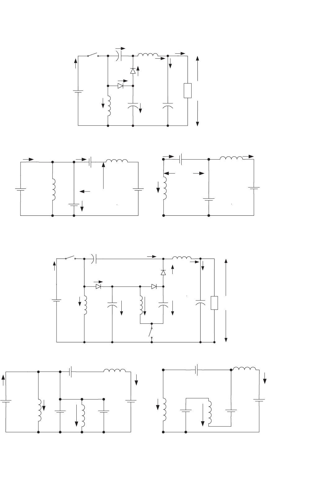
P/O Luo-converter self-lift circuit is shown in Fig. 14.26a.
The equivalent circuits during switch-on and -off periods are
shown in Figs. 14.26b and c. Its output voltage and current are
V
O
=
1
1 −k
V
I
and
I
O
= (1 −k)I
I
The voltage transfer gain in continuous mode is
M
S
=
V
O
V
I
=
I
I
I
O
=
1
1 −k
(14.36)
The variation ratio of the output voltage v
O
in CCM is
ε =
v
O
/2
V
O
=
k
16M
S
1
f
2
C
O
L
2
(14.37)
This converter may work in discontinuous conduction
mode if the frequency f is small, conduction duty k is small,
inductance L is small, and load current is high. The condition
for DCM is
M
S
≤
√
k
z
N
2
(14.38)
The output voltage in DCM is
V
O
=
1 +k
2
(1 −k)
R
2fL
V
I
with
√
k
R
2fL
≥
1
1 −k
(14.39)
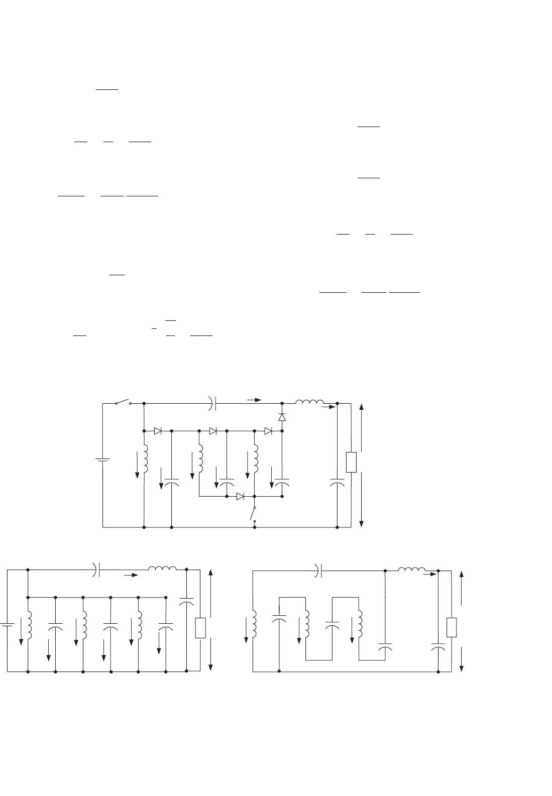
P/O Luo-converter re-lift circuit is shown in Fig. 14.27a.
The equivalent circuits during switch-on and -off periods are
shown in Figs. 14.27b and c. Its output voltage and current are
V
O
=
2
1 −k
V
I
14 DC/DC Conversion Technique and 12 Series Luo-converters 273
V
s
V
IN
c
D
1
R
L
2
i
L2
V
L2
i
D
D
−+
i
C
S
+−
i
IN
L
1
i
D1
i
L1
C
1
i
C1
C
O
i
CO
i
O
V
O
+
−
(a)
V
IN
L
2
V
L2
V
D
−+
i
C
i
IN
L
1
V
L1
C
1
i
C1
+
−
V
IN
V
O
C
−
+
L
2
V
L2
V
D
−
+
i
C
L
1
V
IN
V
O
C
−+
i
L2
+−
(b) (c)
FIGURE 14.26 P/O Luo-converter self-lift circuit: (a) circuit diagram; (b) switch on; and (c) switch off.
V
s
V
IN
c
D
1
i
C
S
+−
i
IN
L
1
i
D1
i
L1
R
L
2
i
L2
V
L2
i
D
D
−+
C
2
i
L2
C
O
i
CO
V
O
+
−
D
2
C
1
i
C1
L
3
S
1
V
S1
−
+
V
C
−+
(a)
V
IN
i
IN
L
1
i
L1
L
2
−
C
2
i
L3
V
O
C
1
L
3
V
IN
V
O
V
IN
C
V
L1
−
+
i
L2
V
D
−
L
1
i
L1
L
2
−+
+
C
2
i
L3
V
O
C
1
L
3
V
IN
V
O
V
IN
C
i
L2
−
(b) (c)
FIGURE 14.27 P/O Luo-converter re-lift circuit: (a) circuit diagram; (b) switch on; and (c) switch off.
274 F. L. Luo and H. Ye
and
I
O
=
1 −k
2
I
I
The voltage transfer gain in CCM is
M
R
=
V
O
V
I
=
I
I
I
O
=
2
1 −k
(14.40)
The variation ratio of the output voltage v
O
in CCM is
ε =
v
O
/2
V
O
=
k
16M
R
1
f
2
C
O
L
2
(14.41)
This converter may work in discontinuous conduction
mode if the frequency f is small, conduction duty k is small,
inductance L is small, and load current is high. The condition
for DCM is
M
R
≤
kz
N
(14.42)
The output voltage in DCM is
V
O
=
2 +k
2
(1 −k)
R
2fL
V
I
with
√
k
R
fL
≥
2
1 −k
(14.43)
V
s
S
c
i
C
L
2
i
L2
V
L2
D
V
C
V
IN
i
L1
D
1
L
1
R
V
O
D
4
L
3
D
2
i
L3
i
L4
L
4
C
3
i
C3
C
O
C
1
i
C1
S
1
V
S1
D
3
C
2
i
C2
(a)
c
L
2
i
L2
V
L2
V
C
V
IN
i
L1
L
1
R
V
O
L
3
i
L3
i
L4
L
4
C
3
i
C3
C
O
C
1
i
C1
C
2
i
C2
c
L
2
i
L2
V
L2
V
C
i
L1
L
1
R
V
O
L
3
i
L3
i
L4
L
4
C
3
C
O
C
1
C
2
(b) (c)
+−
−+
−+
+
−
−
+
−
+
−+
+
−
−+
−+
+
−
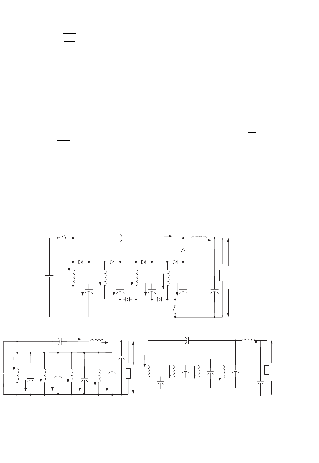
FIGURE 14.28 P/O Luo-converter triple-lift circuit: (a) circuit diagram; (b) switch on; and (c) switch off.
P/O Luo-converter triple-lift circuit is shown in
Fig. 14.28a. The equivalent circuits during switch-on and -off
periods are shown in Figs. 14.28b and c. Its output voltage and
current are
V
O
=
3
1 −k
V
I
and
I
O
=
1 −k
3
I
I
The voltage transfer gain in CCM is
M
T
=
V
O
V
I
=
I
I
I
O
=
3
1 −k
(14.44)
The variation ratio of the output voltage v
O
in CCM is
ε =
v
O
/2
V
O
=
k
16M
T
1
f
2
C
O
L
2
(14.45)
This converter may work in discontinuous conduction
mode if the frequency f is small, conduction duty k is small,
inductance L is small, and load current is high. The condition
for DCM is
14 DC/DC Conversion Technique and 12 Series Luo-converters 275
M
T
≤
3kz
N
2
(14.46)
The output voltage in DCM is
V
O
=
3 +k
2
(1 −k)
R
2fL
V
I
with
√
k
3R
2fL
≥
3
1 −k
(14.47)
P/O Luo-converter quadruple-lift circuit is shown in
Fig. 14.29a. The equivalent circuits during switch-on and -off
periods are shown in Figs. 14.29b and c. Its output voltage and
current are
V
O
=
4
1 −k
V
I
and
I
O
=
1 −k
4
I
I
The voltage transfer gain in CCM is
M
Q
=
V
O
V
I
=
I
I
I
O
=
4
1 −k
(14.48)
V
s
S
+−
c
i
C
D
V
C
−+
L
2
i
L2
V
L2
−+
V
IN
i
L1
D
1
L
1
C
3
i
C3
D
4
C
1
i
C1
L
3
S
1
V
S1
−
+
D
2
D
3
i
L3
i
L4
L
4
C
2
i
C2
C
O
D
6
i
L5
L
5
i
C4
C
4
D
5
R
V
O
+
−
V
L1
(a)
c
i
C
V
C
−+
L
2
i
L2
V
L2
−+
V
IN
i
L1
L
1
C
3
i
C3
C
1
i
C1
L
3
i
L3
i
L4
L
4
C
2
i
C2
C
O
i
L5
L
5
i
C4
C
4
R
V
O
+
−
V
L1
c
V
C
−+
L
2
i
L2
V
L2
−
+
i
L1
L
1
C
3
C
1
L
3
i
L3
i
L4
L
4
C
2
C
O
i
L5
L
5
C
4
R
V
O
+
−
V
L1
(b) (c)
FIGURE 14.29 P/O Luo-converter quadruple-lift circuit: (a) circuit diagram; (b) switch on; and (c) switch off.
The variation ratio of the output voltage v
O
in CCM is
ε =
v
O
/2
V
O
=
k
16M
Q
1
f
2
C
O
L
2
(14.49)
This converter may work in discontinuous conduction
mode if the frequency f is small, conduction duty k is small,
inductance L is small, and load current is high. The condition
for DCM is
M
Q
≤
2kz
N
(14.50)
The output voltage in DCM is
V
O
=
4 +k
2
(1 −k)
R
2fL
V
I
with
√
k
2R
fL
≥
4
1 −k
(14.51)
Summary for all P/O Luo-converters:
M =
V
O
V
I
=
I
I
I
O
; L =
L
1
L
2
L
1
+L
2
; z
N
=
R
fL
; R =
V
O
I
O
To write common formulas for all circuits parameters, we
define that subscript j = 0 for the elementary circuit, j = 1
276 F. L. Luo and H. Ye
for the self-lift circuit, j = 2 for the re-lift circuit, j = 3 for
the triple-lift circuit, j = 4 for the quadruple-lift circuit, and
so on. The voltage transfer gain is
M
j
=
k
h(j)
[j + h(j)]
1 −k
(14.52)
The variation ratio of the output voltage is
ε
j
=
v
O
/2
V
O
=
k
16M
j
1
f
2
C
O
L
2
(14.53)
The condition for discontinuous conduction mode is
k
[1+h(j)]
M
2
j
j + h(j)
2
z
N
≥ 1 (14.54)
The output voltage in discontinuous conduction mode is
V
O−j
=
j + k
[2−h(j)]
1 −k
2
z
N
V
I
(14.55)
where
h(j) =
0 if j ≥ 1
1 if j = 0
(14.56)
is the Hong function.
+
−
i
I
S
L
i
L
V
I
C
L
O
D
C
O
R
+
−
V
O
+
−
V
C1
i
LO
i
O
D
1
C
1
+−
V
C
(a)
i
I
+
−
L
i
L
V
I
C
L
O
C
O
R
+
−
V
O
+
−
V
C1
i
LO
i
O
C
1
+−
V
C
L
i
L
C
L
O
C
O
R
+
−
V
O
+
−
V
C
i
LO
i
O
C
1
+
−
V
C1
(b) (c)
FIGURE 14.30 S P/O Luo-converter self-lift circuit: (a) circuit diagram; (b) switch on; and (c) switch off.
14.3.2 Simplified Positive Output (S P/O)
Luo-converters
Carefully check P/O Luo-converters, we can see that there are
two switches required from re-lift circuit. In order to use only
one switch in all P/O Luo-converters, we modify the circuits.
In this section we introduce following four circuits:
• Simplified self-lift circuit;
• Simplified re-lift circuit;
• Simplified triple-lift circuit;
• Simplified quadruple-lift circuit.
Further lift circuits can be derived from the above circuits.
In all S P/O Luo-converters, we define normalized impedance
z
N
= R/fL.
S P/O Luo-converter self-lift circuit is shown in Fig. 14.30a.
The equivalent circuits during switch-on and -off periods are
shown in Figs. 14.30b and c. Its output voltage and current are
V
O
=
1
1 −k
V
I
and
I
O
= (1 −k)I
I
The voltage transfer gain in CCM is
M
S
=
V
O
V
I
=
I
I
I
O
=
1
1 −k
(14.57)
14 DC/DC Conversion Technique and 12 Series Luo-converters 277
The variation ratio of the output voltage v
O
in CCM is
ε =
v
O
/2
V
O
=
k
128
1
f
3
L
O
C
1
C
O
R
(14.58)
This converter may work in discontinuous conduction
mode if the frequency f is small, conduction duty k is small,
inductance L is small, and load current is high. The condition
for DCM is
M
S
≤
√
k
z
N
2
(14.59)
The output voltage in DCM is
V
O
=
1 +k
2
(1 −k)
R
2fL
V
I
with
√
k
R
2fL
≥
1
1 −k
(14.60)
S P/O Luo-converter re-lift circuit is shown in Fig. 14.31a.
The equivalent circuits during switch-on and -off periods
are shown in Figs. 14.31b and c. Its output voltage and
current are
V
O
=
2
1 −k
V
I
and
I
O
=
1 −k
2
I
I
+
−
i
I
i
I
S
L
i
L
i
L
i
L
V
I
V
I
C
1
C
1
C
1
L
O
L
O
L
O
D
C
O
C
O
C
O
R
+
+
−
−
V
O
V
O
V
O
+
−
V
C1
V
C1
V
C1
i
LO
i
LO
i
LO
i
O
i
O
i
O
D
1
+−
V
C
V
C
V
C
C
L
1
L
1
L
1
D
2
D
11
D
10
i
L1
i
L1
i
L1
V
C2
V
C2
V
C2
+−
C
2
C
2
C
2
(a)
+
−
L
R
+
−
+
−
+−
C
+
−
L
R
+
−
+−
C
+−
(b) (c)
FIGURE 14.31 S P/O Luo-converter re-lift circuit: (a) circuit diagram; (b) switch on; and (c) switch off.
The voltage transfer gain in CCM is
M
R
=
V
O
V
I
=
I
I
I
O
=
2
1 −k
(14.61)
The variation ratio of the output voltage v
O
in CCM is
ε =
v
O
/2
V
O
=
k
128
1
f
3
L
O
C
1
C
O
R
(14.62)
This converter may work in discontinuous conduction
mode if the frequency f is small, conduction duty k is small,
inductance L is small, and load current is high. The condition
for DCM is
M
R
≤
kz
N
(14.63)
The output voltage in DCM is
V
O
=
2 +k
2
(1 −k)
R
2fL
V
I
with
√
k
R
fL
≥
2
1 −k
(14.64)
S P/O Luo triple-lift circuit is shown in Fig. 14.32a. The
equivalent circuits during switch-on and -off periods are
shown in Figs. 14.32b and c. Its output voltage and current are
V
O
=
3
1 −k
V
I