Power electronic handbook
Подождите немного. Документ загружается.

196 J. Rodríguez et al.
L
v
L
v
s
+
i
s
C
P
N
(c)
P
(b)
L
v
L
v
s
+
i
s
C
N
L
v
L
v
s
+
i
s
C
P
N
(d)
v
s
T
1
T
2
v
o
T
4
C
P
T
3
i
s
v
L
(a)
(e)
t
v
s
, i
s
v
s
i
s
v
o
v
o
v
o
N
L
Load
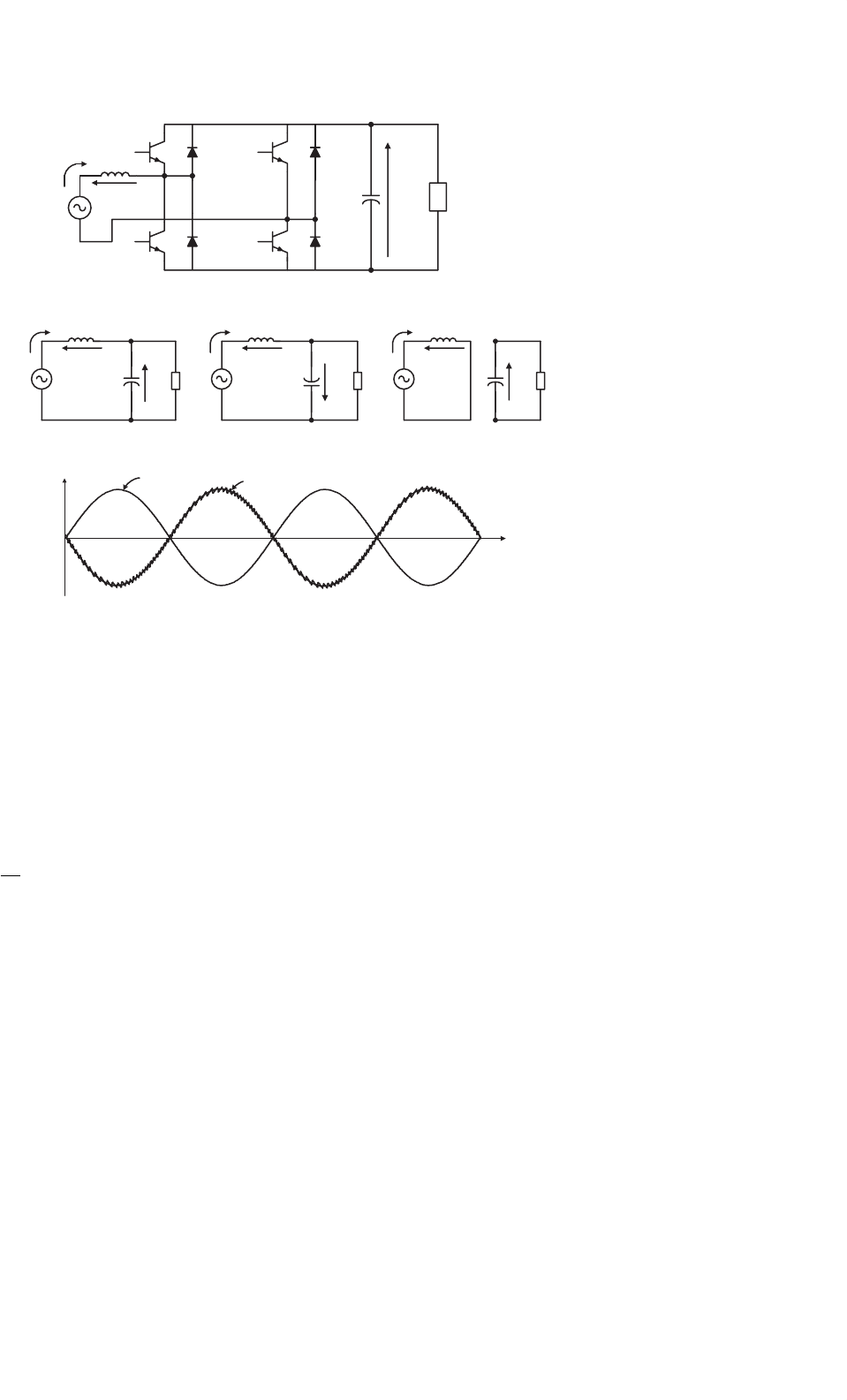
FIGURE 11.33 Single-phase PWM rectifier in bridge connection: (a) power circuit; (b) equivalent circuit with T
1
and T
4
on; (c) equivalent circuit
with T
2
and T
3
on; (d) equivalent circuit with T
1
and T
3
or T
2
and T
4
on; and (e) waveform of the input current during regeneration.
Finally, Fig. 11.33d shows the equivalent circuit with tran-
sistors T
1
and T
3
or T
2
and T
4
are in the on-state. In this case,
the input voltage source is short-circuited through inductor L,
which yields
v
L
= L
di
s
dt
= v
s
(t) + V
0
> 0 (11.32)
Equation (11.32) implies that the current value will depend on
the sign of v
s
.
The waveform of the input current i
s
can be controlled by
appropriately switching transistors T
1
–T
4
or T
2
–T
3
, originat-
ing a similar shape to the one shown in Fig. 11.18a for the
single-phase boost rectifier.
The control strategy for the rectifier is similar to the one
illustrated in Fig. 11.31, for the voltage doubler topology.
The quality of the input current obtained with this rectifier
is the same as presented in Fig. 11.32 for the voltage doubler
configuration.
The input current waveform can be slightly improved if the
state of Fig. 11.33d is used. This can be done by replacing the
hysteresis current control with a more complex linear con-
trol plus a three-level PWM modulator. This method reduces
the semiconductor switching frequency and provides a more
defined current spectrum.
Finally, it must be said that one of the most attractive char-
acteristics of the fully controlled PWM converter in bridge
connection and the voltage doubler is their regeneration capa-
bility. In effect, these rectifiers can deliver power from the load
to the single-phase supply, operating with sinusoidal current
and a high power factor of PF > 0.99. Figure 11.33e shows that
during regeneration, the input current i
s
is 180
◦
out of phase
with respect to the supply voltage v
s
, which means operation
with power factor PF ≈−1 (PF is approximately 1 because of
the small harmonic content in the input current).
11.3.6 Applications of Unity Power Factor
Rectifiers
11.3.6.1 Boost Rectifier Applications
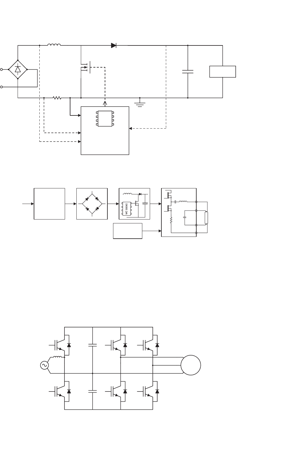
The single-phase boost rectifier has become the most popular
topology for power factor correction (PFC) in general purpose
power supplies. To reduce the costs, the complete control sys-
tem shown in Fig. 11.19 and the gate drive circuit of the power
transistor have been included in a single integrated circuit (IC),
like the UC3854 [10] or MC33262, shown in Fig. 11.34.
11 Single-phase Controlled Rectifiers 197
UC 3854
or
MC33262
LOAD
VOLTAGE
SENSE
CURRENT
SENSE
WAVEFORM
INPUT
AC
LINE
R
S
D
Q
L
C
FIGURE 11.34 Simplified circuit of a power factor corrector with control integrated circuit.
EMI
FILTER
Line
+
PFC
Dimming
Control
Output Stage
Lamp
Rectifier
FIGURE 11.35 Functional block diagram of electronic ballast with power factor correction.
Today there is increased interest in developing high-
frequency electronic ballasts to replace the classical electro-
magnetic ballast present in fluorescent lamps. These electronic
ballasts require an ac–dc converter. To satisfy the harmonic
current injection from electronic equipment and to maintain
a high power quality, a high power factor rectifier can be used,
as shown in Fig. 11.35 [11].
AC
MAINS
+
+
_
+
_
C
1
M
0
C
2
T
1
T
3
T
5
T
2
T
4
T
6
FIGURE 11.36 Low-cost induction motor drive.
11.3.6.2 Voltage Doubler PWM Rectifier
The development of low-cost compact motor drive sys-
tems is a very relevant topic, particularly in the low-power
range. Figure 11.36 shows a low-cost converter for low-power
induction motor drives. In this configuration, a three-phase
induction motor is fed through the converter from a single-
phase power supply. Transistors T
1
,T
2
and capacitors C
1
, C
2
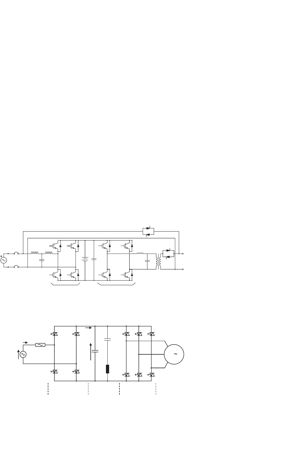
198 J. Rodríguez et al.
constitute the voltage doubler single-phase rectifier, which
controls the dc link voltage and generates sinusoidal input
current, working with close-to-unity power factor [12]. On
the other hand, transistors T
3
,T
4
,T
5
, and T
6
and capacitors
C
1
and C
2
constitute the power circuit of an asymmetric
inverter that supplies the motor. An important characteris-
tic of the power circuit shown in Fig. 11.36 is the capability of
regenerating power to the single-phase mains.
11.3.6.3 PWM Rectifier in Bridge Connection
Distortion of the input current in the line-commutated recti-
fiers with capacitive filtering is particularly critical in the UPS
fed from motor-generator sets. In effect, due to the higher
value of the generator impedance, the current distortion can
originate an unacceptable distortion on the ac voltage, which
affects the behavior of the whole system. For this reason, it is
very attractive to use rectifiers with low distortion in the input
current.
Figure 11.37 shows the power circuit of a single-phase UPS,
which has a PWM rectifier in bridge connection at the input
Output
1f100 V
Input
1f100 V
Inverter
Converter
THY2
THY SW
THY1
TR1
FIGURE 11.37 Single-phase UPS with PWM rectifier.
3
v
s
i
s
I
dc
V
dc
Line +
transformer
4-quadrant
converter
DC - Link Inverter Motor
FIGURE 11.38 Typical power circuit of an ac drive for locomotive.
side. This rectifier generates a sinusoidal input current and
controls the charge of the battery [13].
Perhaps the most typical and widely accepted area of
application of high power factor single-phase rectifiers is in
locomotive drives [14]. An essential prerequisite for proper
operation of voltage source three-phase inverter drives in
modern locomotives is the use of four-quadrant line-side con-
verters, which ensure motoring and braking of the drive, with
reduced harmonics in the input current. Figure 11.38 shows
a simplified power circuit of a typical drive for a locomotive
connected to a single-phase power supply [14], which includes
a high power factor rectifier at the input.
Finally, Fig. 11.39 shows the main circuit diagram of the
300 series Shinkansen train [15]. In this application, ac power
from the overhead catenary is transmitted through a trans-
former to single-phase PWM rectifiers, which provide the dc
voltage for the inverters. The rectifiers are capable of control-
ling the input ac current in an approximate sine waveform
and in phase with the voltage, achieving power factor close to
unity on powering and on regenerative braking. Regenerative
braking produces energy savings and an important operational
flexibility.
11 Single-phase Controlled Rectifiers 199
PWM
CONVERTER SMOOTHING CAPACITOR
PWM INVERTER
OVERHEAD
CATENARY
TRANSFORMER
INDUCTION
MOTORS
GTO THYRISTOR
FIGURE 11.39 Main circuit diagram of 300 series Shinkansen locomotives.
Acknowledgment
The authors gratefully acknowledge the valuable contribution
of Dr. Rubén Peña, and support provided by the Millennium
Science Initiative (ICM) from Mideplan, Chile.
References
1. R. Dwyer and D. Mueller, “Selection of transformers for comercial
buildings,” in Proc. of IEEE/IAS 1992 Annual Meeting, U.S.A., Oct
1992, pp. 1335–1342.
2. D. C. Martins, F. J. M. de Seixas, J. A. Brilhante, and I. Barbi, “A
family of dc-to-dc PWM converters using a new ZVS commutation
cell,” in Proc. IEEE PESC’93, 1993, pp. 524–530.
3. J. Bassett, “New, zero voltage switching, high frequency boost con-
verter topology for power factor correction,” in Proc. INTELEC’95,
1995, pp. 813–820.
4. R. Streit and D. Tollik, “High efficiency telecom rectifier using
a novel soft-switched boost-based input current shaper,” in Proc.
INTELEC’91, 1991, pp. 720–726.
5. Y. Jang and M. M. Jovanovic´, “A new, soft-switched, high-power-
factor boost converter with IGBTs,” presented at the INTELEC’99,
1999, Paper 8-3.
6. M. M. Jovanovic´, “A technique for reducing rectifier reverse-
recovery-related losses in high-voltage, high-power boost convert-
ers,” in Proc. IEEE APEC’97, 1997, pp. 1000–1007.
7. D. M. Mitchell, “AC-DC converter having an improved power
factor,” U.S. Patent 4 412 277, Oct 25, 1983.

200 J. Rodríguez et al.
8. A. F. de Souza and I. Barbi, “A new ZVS-PWM unity power fac-
tor rectifier with reduced conduction losses,” IEEE Trans. Power
Electron, Vol. 10, No. 6, Nov 1995, pp. 746–752.
9. A. F. de Souza and I. Barbi, “A new ZVS semiresonant power factor
rectifier with reduced conduction losses,” IEEE Trans. Ind. Electron,
Vol. 46, No. 1, Feb 1999, pp. 82–90.
10. P. Todd, “UC3854 controlled power factor correction circuit design,”
Application Note U-134, Unitrode Corp.
11. J. Adams, T. Ribarich, and J. Ribarich, “A new control IC for
dimmable high-frequency electronic ballast,” IEEE Applied Power
Electronics Conference APEC’99, USA,1999, pp. 713–719.
12. C. Jacobina, M. Beltrao, E. Cabral, and A. Nogueira, “Induc-
tion motor drive system for low-power applications,” IEEE
Transactions on Industry Applications, Vol. 35, No. 1. Jan/Feb 1999,
pp. 52–60.
13. K. Hirachi, H. Yamamoto, T. Matsui, S. Watanabe, and M. Nakaoka,
“Cost-effective practical developments of high-performance 1kVA
UPS with new system configurations and their specific control imple-
mentations,” European Conference on Power Electronics EPE 95,
Spain 1995, pp. 2035–2040.
14. K. Hückelheim and Ch. Mangold, “Novel 4-quadrant converter con-
trol method,” European Conference on Power Electronics EPE 89,
Germany 1989, pp. 573–576.
15. T. Ohmae and K. Nakamura, “Hitachi’s role in the area of power
electronics for transportation,” Proc. of the IECON’93. Hawai, Nov
1993, pp. 714–718.

12
Three-phase Controlled Rectifiers
Juan W. Dixon, Ph.D.
Department of Electrical
Engineering, Pontificia
Universidad Católica de Chile
Vicuña Mackenna 4860,
Santiago, Chile
12.1 Introduction .......................................................................................... 201
12.2 Line-commutated Controlled Rectifiers....................................................... 201
12.2.1 Three-phase Half-wave Rectifier • 12.2.2 Six-pulse or Double Star Rectifier • 12.2.3 Double
Star Rectifier with Interphase Connection • 12.2.4 Three-phase Full-wave Rectifier or Graetz Bridge
• 12.2.5 Half Controlled Bridge Converter • 12.2.6 Commutation • 12.2.7 Power Factor
• 12.2.8 Harmonic Distortion • 12.2.9 Special Configurations for Harmonic Reduction
• 12.2.10 Applications of Line-commutated Rectifiers in Machine Drives • 12.2.11 Applications in
HVDC Power Transmission • 12.2.12 Dual Converters • 12.2.13 Cycloconverters
• 12.2.14 Harmonic Standards and Recommended Practices
12.3 Force-commutated Three-phase Controlled Rectifiers ................................... 221
12.3.1 Basic Topologies and Characteristics • 12.3.2 Operation of the Voltage Source Rectifier
• 12.3.3 PWM Phase-to-phase and Phase-to-neutral Voltages • 12.3.4 Control of the DC Link
Voltage • 12.3.5 New Technologies and Applications of Force-commutated Rectifiers
Further Reading ..................................................................................... 242
12.1 Introduction
Three-phase controlled rectifiers have a wide range of appli-
cations, from small rectifiers to large high voltage direct
current (HVDC) transmission systems. They are used for
electrochemical processes, many kinds of motor drives, trac-
tion equipment, controlled power supplies and many other
applications. From the point of view of the commutation
process, they can be classified into two important categories:
line-commutated controlled rectifiers (thyristor rectifiers) and
force-commutated pulse width modulated (PWM) rectifiers.
12.2 Line-commutated Controlled
Rectifiers
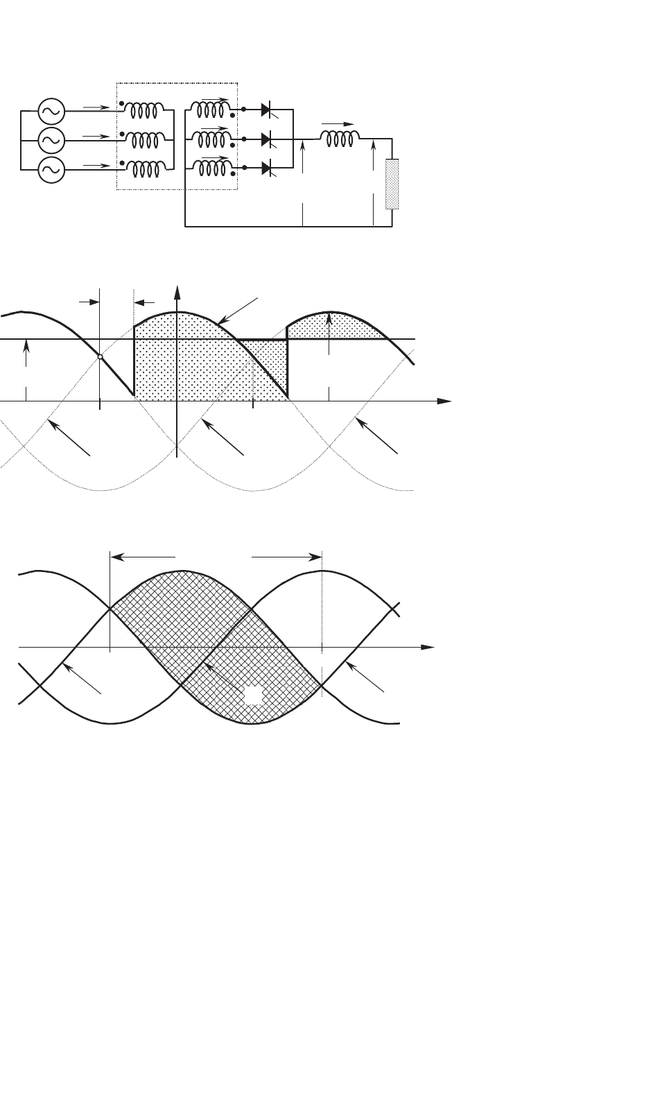
12.2.1 Three-phase Half-wave Rectifier
Figure 12.1 shows the three-phase half-wave rectifier topol-
ogy. To control the load voltage, the half-wave rectifier uses
three common-cathode thyristor arrangement. In this figure,
the power supply and the transformer are assumed ideal. The
thyristor will conduct (ON state), when the anode-to-cathode
voltage v
AK
is positive and a firing current pulse i
G
is applied to
the gate terminal. Delaying the firing pulse by an angle α con-
trols the load voltage. As shown in Fig. 12.2, the firing angle α
is measured from the crossing point between the phase supply
voltages. At that point, the anode-to-cathode thyristor voltage
v
AK
begins to be positive. Figure 12.3 shows that the possible
range for gating delay is between α = 0
◦
and α = 180
◦
, but
because of commutation problems in actual situations, the
maximum firing angle is limited to around 160
◦
. As shown
in Fig. 12.4, when the load is resistive, current i
d
has the
same waveform of the load voltage. As the load becomes more
and more inductive, the current flattens and finally becomes
constant. The thyristor goes to the non-conducting condition
(OFF state) when the following thyristor is switched ON,or
the current, tries to reach a negative value.
With the help of Fig. 12.2, the load average voltage can be
evaluated, and is given by:
V
D
=
V
MAX
2
3
π
π/3+α
−π/3+α
cos ωt ·d
(
ωt
)
= V
MAX
sin
π
3
π
3
·cos α ≈ 1.17 ·V
rms
f −N
·cos α (12.1)
where V
MAX
is the secondary phase-to-neutral peak voltage,
V
rms
f −N
its root mean square (rms) value and ω is the angu-
lar frequency of the main power supply. It can be seen from
Eq. (12.1) that the load average voltage V
D
is modified by
Copyright © 2007, 2001, Elsevier Inc.
All rights reserved.
201
202 J. W. Dixon
v
c
Y Y
i
D
v
D
L
D
v
a
v
b
v
A
v
B
v
C
i
A
i
B
i
C
i
a
i
b
i
c
V
D
LOAD
+
_
FIGURE 12.1 Three-phase half-wave rectifier.
V
MAX
ωt
−π/3 π/3
v
c
v
a
v
b
v
D
V
D
A
1
=A
2
α
A
2
A
1
A
2
A
1
FIGURE 12.2 Instantaneous dc voltage v
D
, average dc voltage V
D
, and firing angle α.
ωt
v
c
v
b
v
a
range of α
0°
180°
FIGURE 12.3 Possible range for gating delay in angle α.
changing firing angle α. When α<90
◦
, V
D
is positive and
when α>90
◦
, the average dc voltage becomes negative. In
such a case, the rectifier begins to work as an inverter and the
load needs to be able to generate power reversal by reversing
its dc voltage.
The ac currents of the half-wave rectifier are shown in
Fig. 12.5. This drawing assumes that the dc current is constant
(very large L
D
). Disregarding commutation overlap, each valve
conducts during 120
◦
per period. The secondary currents (and
thyristor currents) present a dc component that is undesirable,
and makes this rectifier not useful for high power applications.
The primary currents show the same waveform, but with the
dc component removed. This very distorted waveform requires
an input filter to reduce harmonics contamination.
The current waveforms shown in Fig. 12.5 are useful for
designing the power transformer. Starting from:
VA
prim
= 3 ·V
rms
(prim)f −N
·I
rms
prim
VA
sec
= 3 ·V
rms
(sec)f −N
·I
rms
sec
(12.2)
P
D
= V
D
·I
D
12 Three-phase Controlled Rectifiers 203
v
D
i
D
v
D
i
D
v
D
i
D
v
D
i
D
(a) R > 0, L
D
=0
(b) R > 0, L
D
>0
(d) R small, L
D
very large
(c) R > 0, L
D
large
FIGURE 12.4 DC current waveforms.
where VA
prim
and VA
sec
are the ratings of the transformer
for the primary and secondary side respectively. Here P
D
is
the power transferred to the dc side. The maximum power
transfer is with α = 0
◦
(or α = 180
◦
). Then, to establish a
relation between ac and dc voltages, Eq. (12.1) for α = 0
◦
is
required:
V
D
= 1.17 ·V
rms
(sec)f −N
(12.3)
and:
V
D
= 1.17 ·a ·V
rms
(prim)f −N
(12.4)
where a is the secondary to primary turn relation of the trans-
former. On the other hand, a relation between the currents is
also possible to obtain. With the help of Fig. 12.5:
I
rms
sec
=
I
D
√
3
(12.5)
I
rms
prim
= a ·
I
D
√
2
3
(12.6)
Combining Eqs. (12.2) to (12.6), it yields:
VA
prim
= 1.21 ·P
D
VA
sec
= 1.48 ·P
D
(12.7)
Equation (12.7) shows that the power transformer has to be
oversized 21% at the primary side, and 48% at the secondary
side. Then, a special transformer has to be built for this recti-
fier. In terms of average VA, the transformer needs to be 35%
larger that the rating of the dc load. The larger rating of the
secondary with respect to primary is because the secondary
carries a dc component inside the windings. Furthermore, the
transformer is oversized because the circulation of current har-
monics does not generate active power. Core saturation, due to
204 J. W. Dixon
v
c
v
b
I
D
V
MAX
ω
t
v
b
v
a
v
D
v
a
i
a
i
b
i
c
i
B
i
C
i
A
–I
D
/ 3
2I
D
/ 3
I
D
α
FIGURE 12.5 AC current waveforms for the half-wave rectifier.
L
D
I
D
v
B
v
C
v
A
i
A
∆
i
B
i
A
i
C
N
i
a
v
a
i
b
v
b
i
c
v
c
i
1
v
1
i
2
v
2
i
3
v
3
v
D
V
D
+
_
FIGURE 12.6 Six-pulse rectifier.
the dc components inside the secondary windings, also needs
to be taken in account for iron oversizing.
12.2.2 Six-pulse or Double Star Rectifier
The thyristor side windings of the transformer shown in
Fig. 12.6 form a six-phase system, resulting in a six-pulse
starpoint (midpoint connection). Disregarding commutation
overlap, each valve conducts only during 60
◦
per period. The
direct voltage is higher than that from the half-wave rectifier
and its average value is given by:
V
D
=
V
MAX
π
3
π/6+α
−π/6+α
cos ωt ·d
(
ωt
)
= V
MAX
sin
π
6
π
6
·cos α ≈ 1.35 · V
rms
f −N
·cos α (12.8)
The dc voltage ripple is also smaller than the one gener-
ated by the half-wave rectifier, due to the absence of the third
harmonic with its inherently high amplitude. The smoothing
12 Three-phase Controlled Rectifiers 205
v
b
v
D
i
b
i
c
i
B
∆
i
A
∆
i
A
v
1
v
a
v
3
v
c
v
2
v
a
v
3
i
a
i
1
V
D
I
D
wt
60
°
α
FIGURE 12.7 AC current waveforms for the six-pulse rectifier.
reactor L
D
is also considerably smaller than the one needed
for a three-pulse (half-wave) rectifier.
The ac currents of the six-pulse rectifier are shown in
Fig. 12.7. The currents in the secondary windings present a
dc component, but the magnetic flux is compensated by the
double star. As can be observed, only one valve is fired at a time
and then this connection in no way corresponds to a parallel
connection. The currents inside the delta show a symmetrical
waveform with 60
◦
conduction. Finally, due to the particular
transformer connection shown in Fig. 12.6, the source currents
also show a symmetrical waveform, but with 120
◦
conduction.
Evaluation of the the rating of the transformer is done in
similar fashion to the way the half-wave rectifier is evaluated:
VA
prim
= 1.28 ·P
D
VA
sec
= 1.81 ·P
D
(12.9)
Thus the transformer must be oversized 28% at the primary
side and 81% at the secondary side. In terms of size it has an
average apparent power of 1.55 times the power P
D
(55% over-
sized). Because of the short conducting period of the valves,
the transformer is not particularly well utilized.
12.2.3 Double Star Rectifier with Interphase
Connection
This topology works as two half-wave rectifiers in parallel, and
is very useful when high dc current is required. An optimal
way to reach both good balance and elimination of harmon-
ics is through the connection shown in Fig. 12.8. The two
rectifiers are shifted by 180
◦
, and their secondary neutrals
are connected through a middle-point autotransformer called
“interphase transformer.” The interphase transformer is con-
nected between the two secondary neutrals and the middle
point at the load return. In this way, both groups operate in
parallel. Half the direct current flows in each half of the inter-
phase transformer, and then its iron core does not become
saturated. The potential of each neutral can oscillate inde-
pendently, generating an almost triangular voltage waveform
(v
T
) in the interphase transformer, as shown in Fig. 12.9.
As this converter work like two half-wave rectifiers connected
in parallel, the load average voltage is the same as in Eq. (12.1):
V
D
≈ 1.17 ·V
rms
f −N
·cos α (12.10)
where V
rms
f −N
is the phase-to-neutral rms voltage at the valve
side of the transformer (secondary).
The Fig. 12.9 also shows the two half-wave rectifier voltages,
related to their respective neutrals. Voltage v
D1
represents the
potential between the common cathode connection and the
neutral N1. The voltage v
D2
is between the common cathode
connection and N2. It can be seen that the two instantaneous
voltages are shifted, which gives as a result, a voltage v
D
that
is smoother than v
D1
and v
D2
.
Figure 12.10 shows how v
D
, v
D1
, v
D2
, and v
T
change when
the firing angle changes from α = 0
◦
to 180
◦
.