Power electronic handbook
Подождите немного. Документ загружается.


206 J. W. Dixon
v
3
v
1
v
2
v
D
v
A
v
B
i
B
v
C
i
C
i
A
i
A
i
1
i
2
i
3
i
a
v
a
i
b
v
b
i
c
v
c
N1
N2
v
D1
v
D2
v
T
V
D
L
D
+
_
I
D
½ID ½ID
D
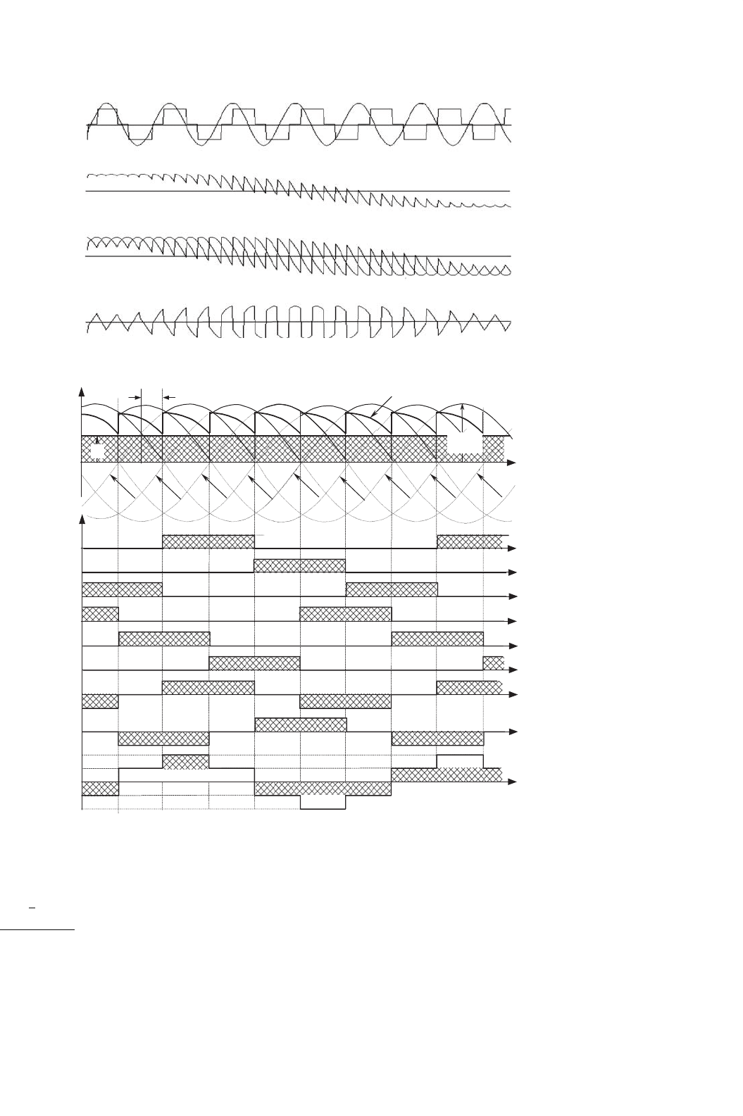
FIGURE 12.8 Double star rectifier with interphase transformer.
v
a
i
a
v
D
v
D1
v
D2
v
T
wt
V
D
FIGURE 12.9 Operation of the interphase connection for α = 0
◦
.
The transformer rating in this case is:
VA
prim
= 1.05 ·P
D
VA
sec
= 1.48 ·P
D
(12.11)
And the average rating power will be 1.26 P
D
, which is better
than the previous rectifiers (1.35 for the half-wave rectifier and
1.55 for the six-pulse rectifier). Thus the transformer is well
utilized. Figure 12.11 shows ac current waveforms for a rectifier
with interphase transformer.
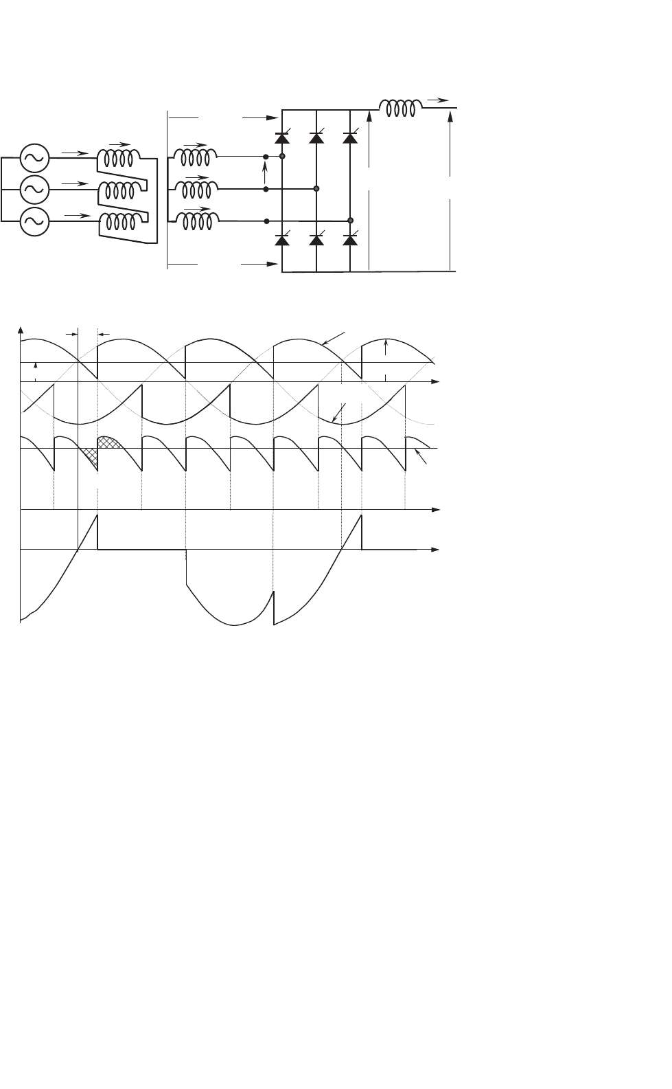
12.2.4 Three-phase Full-wave Rectifier or Graetz
Bridge
Parallel connection via interphase transformers permits the
implementation of rectifiers for high current applications.
Series connection for high voltage is also possible, as shown
in the full-wave rectifier of Fig. 12.12. With this arrangement,
it can be seen that the three common cathode valves generate
a positive voltage with respect to the neutral, and the three
common anode valves produce a negative voltage. The result
is a dc voltage, twice the value of the half-wave rectifier. Each
half of the bridge is a three-pulse converter group. This bridge
connection is a two-way connection and alternating currents
flow in the valve-side transformer windings during both half
periods, avoiding dc components into the windings, and satu-
ration in the transformer magnetic core. These characteristics
make the so-called Graetz bridge the most widely used line-
commutated thyristor rectifier. The configuration does not
need any special transformer and works as a six-pulse rectifier.
The series characteristic of this rectifier produces a dc volt-
age twice the value of the half-wave rectifier. The load average
voltage is given by:
V
D
=
2 ·V
MAX
2
3
π
π/3+α
−π/3+α
cos ωt ·d
(
ωt
)
= 2 ·V
MAX
sin
π
3
π
3
·cos α ≈ 2.34 · V
rms
f −N
·cos α (12.12)
12 Three-phase Controlled Rectifiers 207
v
a
, i
a
v
D1
, v
D2
v
D
v
T
α=0°
α=180°
FIGURE 12.10 Firing angle variation from α = 0
◦
to 180
◦
.
v
c
I
D
w t
v
b
v
a
v
D
v
a
i
a
i
b
i
c
i
2
i
1
I
D
/2
V
MAX
i
3
i
B
D
i
A
D
i
A
v
b
v
3
v
3
v
2
v
1
a
FIGURE 12.11 AC current waveforms for the rectifier with interphase transformer.
or
V
D
=
3 ·
√
2 ·V
sec
f −f
π
cos α ≈ 1.35 · V
sec
f −f
·cos α (12.13)
where V
MAX
is the peak phase-to-neutral voltage at the
secondary transformer terminals, V
rms
f −N
its rms value,
and V
sec
f −f
the rms phase-to-phase secondary voltage, at the
valve terminals of the rectifier.
Figure 12.13 shows the voltages of each half-wave bridge of
this topology, v
pos
D
and v
neg
D
, the total instantaneous dc volt-
age v
D
, and the anode-to-cathode voltage v
AK
in one of the
bridge thyristors. The maximum value of v
AK
is
√
3 · V
MAX
,
208 J. W. Dixon
I
D
L
D
v
D
pos
v
D
neg
v
D
i
A
∆
i
A
v
A
i
B
v
B
i
C
v
C
i
a
i
b
v
b
i
c
v
c
v
a
v
AK
_
+
V
D
V
f-f
sec
FIGURE 12.12 Three-phase full-wave rectifier or Graetz bridge.
v
c
v
b
I
D
V
MAX
v
c
v
a
v
a
v
D
pos
A1
A2
A1 = A2
V
D
v
D
v
AK
wt
v
D
neg
a
FIGURE 12.13 Voltage waveforms for the Graetz bridge.
which is the same as that of the half-wave converter and
the interphase transformer rectifier. The double star recti-
fier presents a maximum anode-to-cathode voltage of two
times V
MAX
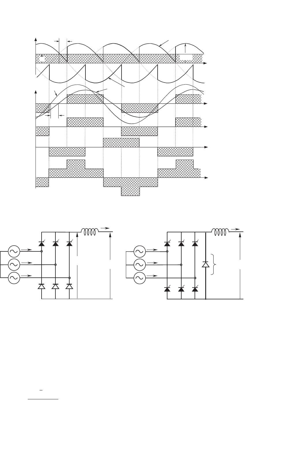
. Figure 12.14 shows the currents of the rectifier,
which assumes that L
D
is large enough to keep the dc current
smooth. The example is for the same Y transformer connec-
tion shown in the topology of Fig. 12.12. It can be noted that
the secondary currents do not carry any dc component, thereby
avoiding overdesign of the windings and transformer satura-
tion. These two figures have been drawn for a firing angle, α
of approximately 30
◦
. The perfect symmetry of the currents in
all windings and lines is one of the reasons why this rectifier
is the most popular of its type. The transformer rating in this
case is
VA
prim
= 1.05 ·P
D
VA
sec
= 1.05 ·P
D
(12.14)
As can be noted, the transformer needs to be oversized
only 5%, and both primary and secondary windings have the
same rating. Again, this value can be compared with the pre-
vious rectifier transformers: 1.35P
D
for the half-wave rectifier,
1.55P
D
for the six-pulse rectifier, and 1.26P
D
for the inter-
phase transformer rectifier. The Graetz bridge makes excellent
use of the power transformer.
12.2.5 Half Controlled Bridge Converter
The fully controlled three-phase bridge converter shown in
Fig. 12.12 has six thyristors. As already explained here, this
circuit operates as a rectifier when each thyristor has a firing
angle α<90
◦
and functions as an inverter for α>90
◦
.If
inverter operation is not required, the circuit may be simplified
by replacing three controlled rectifiers with power diodes, as
in Fig. 12.15a. This simplification is economically attractive
12 Three-phase Controlled Rectifiers 209
v
c
v
b
I
D
V
MAX
wt
v
c
i
a
i
B
D
i
A
D
i
A
v
D
pos
v
D
neg
v
a
v
a
i
a1
f
1
v
a
(a)
(b)
(e)
(d)
(c)
a
FIGURE 12.14 Current waveforms for the Graetz bridge.
(b)
+
_
+
_
(a)
I
D
L
D
v
D
i
A
v
A
i
B
v
B
i
C
v
C
V
D
I
D
L
D
v
D
i
A
v
A
i
B
v
B
i
C
v
C
V
D
FIGURE 12.15 One-quadrant bridge converter circuits: (a) half-controlled bridge and (b) free-wheeling diode bridge.
because diodes are considerably less expensive than thyristors
and they do not require firing angle control electronics.
The half controlled bridge, or “semiconverter,” is analyzed
by considering it as a phase-controlled half-wave circuit in
series with an uncontrolled half-wave rectifier. The average dc
voltage is given by the following equation
V
D
=
3 ·
√
2 ·V
sec
f −f
2π
(1 +cos α) (12.15)
Then, the average voltage V
D
never reaches negative values.
The output voltage waveforms of half-controlled bridge are
similar to those of a fully controlled bridge with a free-wheeling
diode. The advantage of the free-wheeling diode connection,
shown in Fig. 12.15b is that there is always a path for the
dc current, independent of the status of the ac line and of
the converter. This can be important if the load is inductive–
resistive with a large time constant, and there is an interruption
in one or more of the line phases. In such a case, the load
current could commutate to the free-wheeling diode.
210 J. W. Dixon
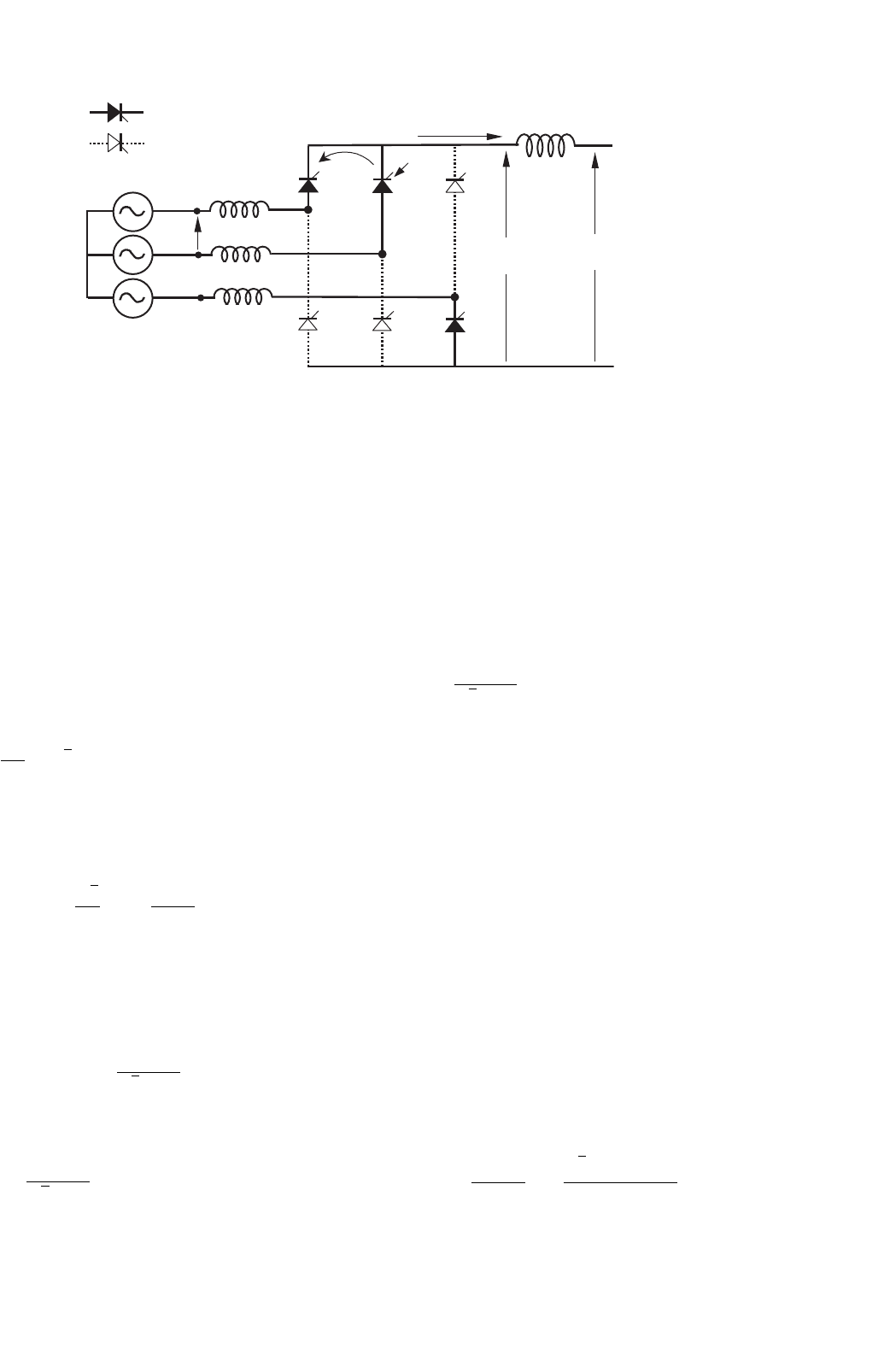
i
G
i
sc
V
f-f
L
S
L
S
L
D
I
D
T1 T2
T3
T5
T6
T4
V
D
v
D
v
A
v
B
v
C
L
S
N
ON
OFF
FIGURE 12.16 Commutation process.
12.2.6 Commutation
The description of the converters in the previous sections was
based upon assumption that the commutation was instanta-
neous. In practice this is not possible, because the transfer
of current between two consecutive valves in a commuta-
tion group takes a finite time. This time, called overlap time,
depends on the phase-to-phase voltage between the valves par-
ticipating in the commutation process, and the line inductance
L
S
between the converter and power supply. During the over-
lap time, two valves conduct, and the phase-to-phase voltage
drops entirely on the inductances L
S
. Assuming the dc current
I
D
to be smooth and with the help of Fig. 12.16, the following
relation is deduced
2L
S
·
di
sc
dt
=
√
2 ·V
f −f
sin ωt = v
A
−v
B
(12.16)
where i
sc
is the current in the valve being fired during the
commutation process (thyristor T2 in Fig. 12.16). This current
can be evaluated, and it yields
i
sc
=−
√
2
2L
S
·V
f −f
cos ωt
ω
+C (12.17)
The constant “C” is evaluated through initial conditions at
the instant when T2 is ignited. In terms of angle, when ωt = α
when ωt = α, i
sc
= 0
∴ C =
V
sec
f −f
√
2 ·ωL
S
cos α (12.18)
Replacing Eq. (12.18) in (12.17):
i
sc
=
V
f −f
√
2 ·ωL
S
·
(
cos α −cos ωt
)
(12.19)
Before commutation, the current I
D
was carried by thyristor
T1 (see Fig. 12.16). During the commutation time, the load
current I
D
remains constant, i
sc
returns through T1, and T1
is automatically switched off when the current i
sc
reaches the
value of I
D
. This happens because thyristors cannot conduct
in reverse direction. At this moment, the overlap time lasts
and the current I
D
is then conducted by T2. In terms of angle,
when ωt = α +µ, i
sc
= I
D
, where µ is defined as the “overlap
angle.” Replacing this final condition in Eq. (12.19) yields
I
D
=
V
sec
f −f
√
2 ·ωL
S
·
[
cos α −cos
(
α +µ
)
]
(12.20)
To avoid confusion in a real analysis, it has to be remem-
bered that V
f −f
corresponds to the secondary voltage in case of
transformer utilization. For this reason, the abbreviation “sec”
has been added to the phase-to-phase voltage in Eq. (12.20).
During commutation, two valves conduct at a time, which
means that there is an instantaneous short circuit between
the two voltages participating in the process. As the induc-
tances of each phase are the same, the current i
sc
produces the
same voltage drop in each L
S
, but with opposite sign because
this current flows in reverse direction and with opposite slope
in each inductance. The phase with the higher instantaneous
voltage suffers a voltage drop −v and the phase with the
lower voltage suffers a voltage increase +v. This situation
affects the dc voltage V
C
, reducing its value an amount V
med
.
Figure 12.17 shows the meanings of v, V
med
, µ, and i
sc
.
The area V
med
showed in Fig. 12.17, represents the loss of
voltage that affects the average voltage V
C
, and can be evalu-
ated through the integration of v during the overlap angle
µ. The voltage drop v can be expressed as
v =
v
A
−v
B
2
=
√
2 ·V
sec
f −f
sin ωt
2
(12.21)

12 Three-phase Controlled Rectifiers 211
i
a
i
c
m
v
D
v
D
pos
v
b
v
a
I
D
wt
DV
med
v
c
Dv
Dv
i
b
i
sc
a
FIGURE 12.17 Effect of the overlap angle on the voltages and currents.
Integrating Eq. (12.21) into the corresponding period
(60
◦
) and interval (µ) and starting at the instant when the
commutation begins (α)
V
med
=
3
π
·
1
2
α+µ
α
√
2 ·V
sec
f −f
sin ωt ·dωt (12.22)
V
med
=
3 ·V
sec
f −f
π ·
√
2
[
cos α −cos
(
α +µ
)
]
(12.23)
Subtracting V
med
in Eq. (12.13)
V
D
=
3 ·
√
2 ·V
sec
f −f
π
cos α −V
med
(12.24)
V
D
=
3 ·
√
2 ·V
sec
f −f
2π
[
cos α +cos
(
α +µ
)
]
(12.25)
or
V
D
=
3 ·
√
2 ·V
sec
f −f
π
cos
α +
µ
2
cos
µ
2
(12.26)
Equations (12.20) and (12.25) can be written as a func-
tion of the primary winding of the transformer, if there is any
transformer.
I
D
=
a ·V
prim
f −f
√
2 ·ωL
S
·
[
cos α −cos
(
α +µ
)
]
(12.27)
V
D
=
3 ·
√
2 ·a ·V
prim
f −f
2π
[
cos α +cos
(
α +µ
)
]
(12.28)
where a = V
sec
f −f
/V
prim
f −f
. With Eqs. (12.27) and (12.28) one gets
V
D
=
3 ·
√
2
π
·a ·V
prim
f −f
cos α −
3I
D
ωL
S
π
(12.29)
Equation (12.29) allows a very simple equivalent circuit of
the converter to be made, as shown in Fig. 12.18. It is impor-
tant to note that the equivalent resistance of this circuit is not
real, because it does not dissipate power.
From the equivalent circuit, regulation curves for the rec-
tifier under different firing angles are shown in Fig. 12.19. It
should be noted that these curves correspond only to an ideal
situation, but helps in understanding the effect of voltage drop
v on dc voltage. The commutation process and the overlap
angle also affects the voltage v
a
and anode-to-cathode thyristor
voltage, as shown in Fig. 12.20.
V
D
I
D
3wL
S
/p
(virtual resistance)
+
_
(3√2/p)aV
f-f
cosa
FIGURE 12.18 Equivalent circuit for the converter.
212 J. W. Dixon
V
D
I
D
3wL
S
/p
.
I
Do
I
Do
(3√2/p)aV
f-f
(3√2/p)a V
f-f
cosa
1
(3√2/p)a V
f-f
cosa
2
α
1
α
2
>α
1
α=0
°
FIGURE 12.19 DC voltage regulation curves for rectifier operation.
12.2.7 Power Factor
The displacement factor of the fundamental current, obtained
from Fig. 12.14 is
cos φ
1
= cos α (12.30)
In the case of non-sinusoidal current, the active power
delivered per phase by the sinusoidal supply is
P =
1
T
T
0
v
a
(t)i
a
(t)dt = V
rms
a
I
rms
a1
cos φ
1
(12.31)
where V
rms
a
is the rms value of the voltage v
a
and I
rms
a1
the rms
value of i
a1
(fundamental component of i
a
). Analog relations
can be obtained for v
b
and v
c
.
The apparent power per phase is given by
S = V
rms
a
I
rms
a
(12.32)
The power factor is defined by
PF =
P
S
(12.33)
m
ma
wt
v
AK
v
a
i
a
FIGURE 12.20 Effect of the overlap angle on v
a
and on thyristor voltage v
AK
.
By substituting Eqs. (12.30), (12.31), and (12.32) into
Eq. (12.33), the power factor can be expressed as follows
PF =
I
rms
a1
I
rms
a
cos α (12.34)
This equation shows clearly that due to the non-sinusoidal
waveform of the currents, the power factor of the rectifier is
negatively affected by both the firing angle α and the distortion
of the input current. In effect, an increase in the distortion
of the current produces an increase in the value of I
rms
a
in
Eq. (12.34), which deteriorates the power factor.
12.2.8 Harmonic Distortion
The currents of the line-commutated rectifiers are far from
being sinusoidal. For example, the currents generated from the
Graetz rectifier (see Fig. 12.14b) have the following harmonic
content
i
A
=
2
√
3
π
I
D
(cos ωt −
1
5
cos 5ωt +
1
7
cos 7ωt
−
1
11
cos 11ωt +...) (12.35)
Some of the characteristics of the currents, obtained from
Eq. (12.35) include: (i) the absence of triple harmonics; (ii) the
presence of harmonics of order 6k ± 1 for integer values of k;
(iii) those harmonics of orders 6k +1 are of positive sequence;
(iv) those of orders 6k − 1 are of negative sequence; (v) the
rms magnitude of the fundamental frequency is
I
1
=
√
6
π
I
D
(12.36)
12 Three-phase Controlled Rectifiers 213
and (vi) the rms magnitude of the nth harmonic is
I
n
=
I
1
n
(12.37)
If either, the primary or the secondary three-phase wind-
ings of the rectifier transformer are connected in delta, the
ac side current waveforms consist of the instantaneous differ-
ences between two rectangular secondary currents 120
◦
apart
as shown in Fig. 12.14e. The resulting Fourier series for the
current in phase “a” on the primary side is
i
A
=
2
√
3
π
I
D
(cos ωt +
1
5
cos 5ωt −
1
7
cos 7ωt
−
1
11
cos 11ωt +...) (12.38)
This series differs from that of a star connected transformer
only by the sequence of rotation of harmonic orders 6k ± 1
for odd values of k, i.e. the 5th, 7th, 17th, 19th, etc.
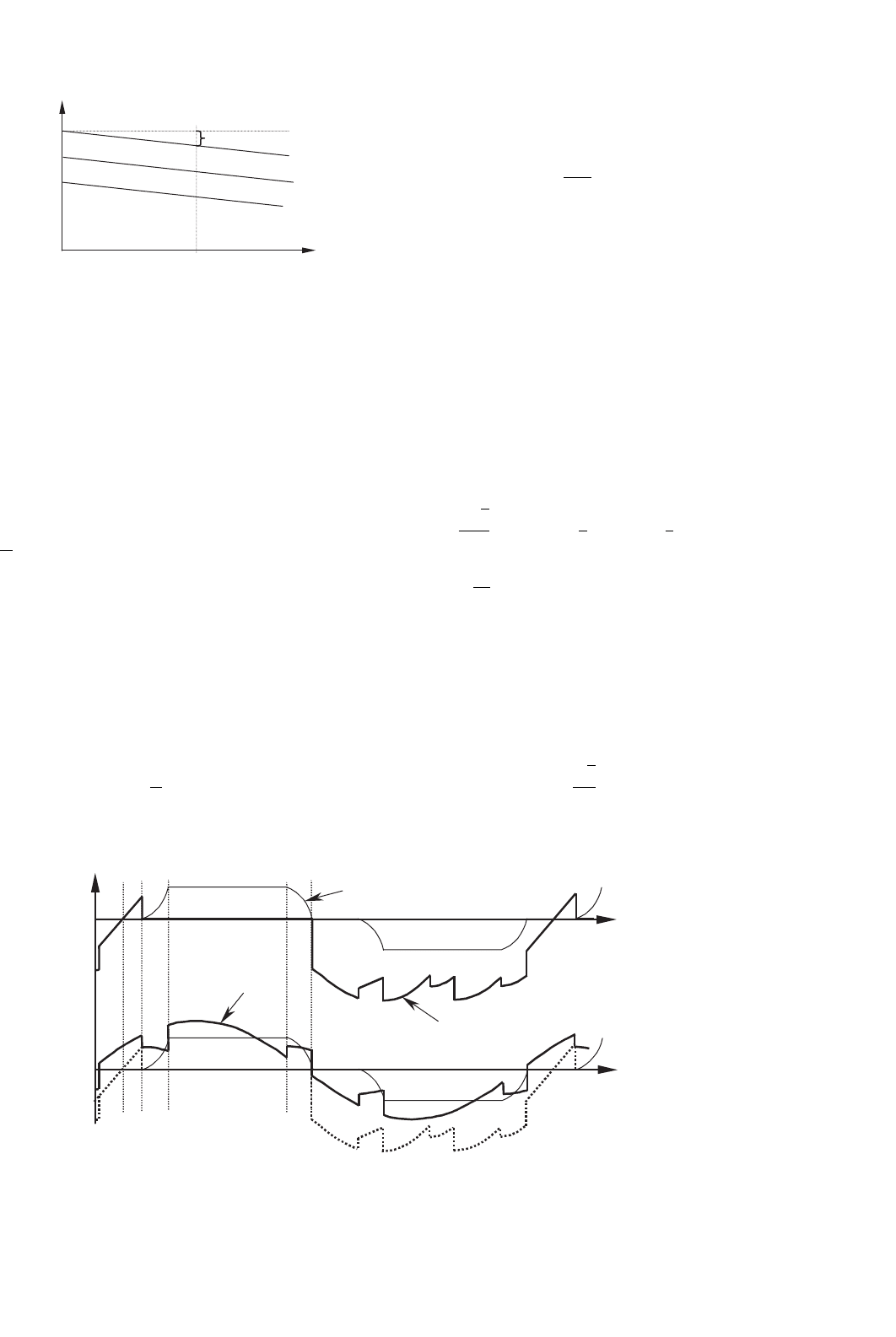
12.2.9 Special Configurations for Harmonic
Reduction
A common solution for harmonic reduction is through the
connection of passive filters, which are tuned to trap a partic-
ular harmonic frequency. A typical configuration is shown in
Fig. 12.21.
However, harmonics also can be eliminated using special
configurations of converters. For example, 12-pulse configu-
ration consists of two sets of converters connected as shown
Y
v
A
i
A
i
B
i
C
i
a
Y
i
b
Y
i
c
Y
i
a
D
i
b
D
i
c
D
I
D
D
FIGURE 12.22 12-pulse rectifier configuration.
5th 7th 11th 13th 17th
to ∞
FIGURE 12.21 Typical passive filter for one phase.
in Fig. 12.22. The resultant ac current is given by the sum of
the two Fourier series of the star connection (Eq. (12.35)) and
delta connection transformers (Eq. (12.38))
i
A
= 2
2
√
3
π
I
D
(cos ωt −
1
11
cos 11ωt +
1
13
cos 13ωt
−
1
23
cos 23ωt +...) (12.39)
The series only contains harmonics of order 12k ± 1.
The harmonic currents of orders 6k ± 1 (with k odd), i.e.
5th, 7th, 17th, 19th, etc. circulate between the two converter
transformers but do not penetrate the ac network.
The resulting line current for the 12-pulse rectifier, shown
in Fig. 12.23, is closer to a sinusoidal waveform than previous
line currents. The instantaneous dc voltage is also smoother
with this connection.
214 J. W. Dixon
wt
i
A
FIGURE 12.23 Line current for the 12-pulse rectifier.
i
A
i
B
i
C
Y
FIGURE 12.24 DC ripple reinjection technique for 48-pulse operation.
Higher pulse configuration using the same principle is also
possible. The 12-pulse rectifier was obtained with a 30
◦
phase
shift between the two secondary transformers. The addition of
further, appropriately shifted, transformers in parallel provides
the basis for increasing pulse configurations. For instance,
24-pulse operation is achieved by means of four transform-
ers with 15
◦
phase shift, and 48-pulse operation requires eight
transformers with 7.5
◦
phase shift (transformer connections
in zig-zag configuration).
Although theoretically possible, pulse numbers above 48 are
rarely justified due to the practical levels of distortion found in
the supply voltage waveforms. Further, the converter topology
becomes more and more complicated.
An ingenious and very simple way to reach high pulse oper-
ation is shown in Fig. 12.24. This configuration is called dc
ripple reinjection. It consists of two parallel converters con-
nected to the load through a multistep reactor. The reactor
uses a chain of thyristor-controlled taps, which are connected
to symmetrical points of the reactor. By firing the thyristors
located at the reactor at the right time, high-pulse operation
is reached. The level of pulse operation depends on the num-
ber of thyristors connected to the reactor. They multiply the
basic level of operation of the two converters. The example,
is Fig. 12.24, shows a 48-pulse configuration, obtained by
the multiplication of basic 12-pulse operation by four reac-
tor thyristors. This technique also can be applied to series
connected bridges.
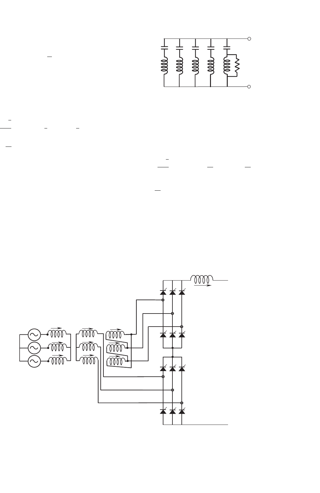
Another solution for harmonic reduction is the utilization of
active power filters. Active power filters are special pulse width
modulated (PWM) converters, able to generate the harmonics
the converter requires. Figure 12.25 shows a current controlled
shunt active power filter.
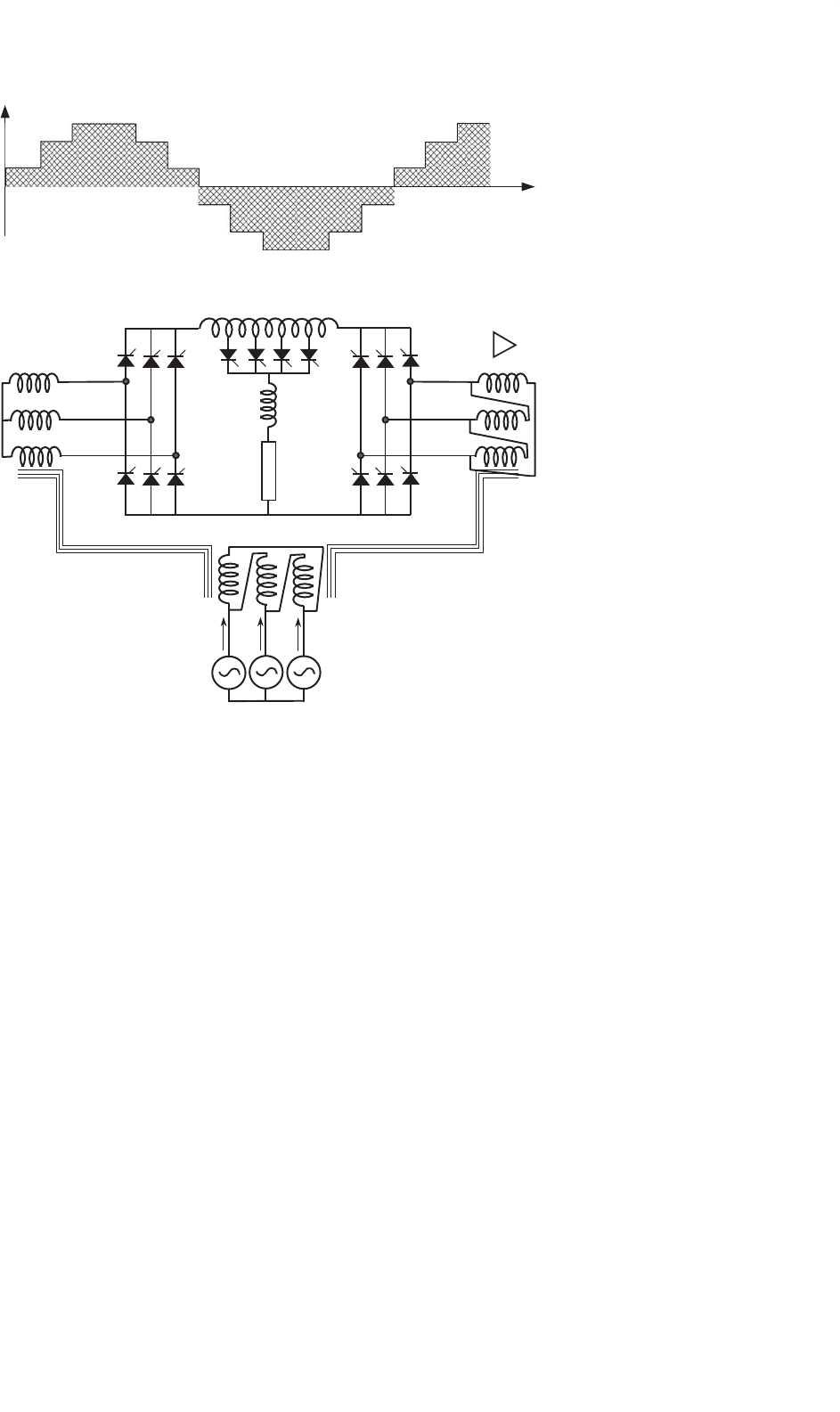
12.2.10 Applications of Line-commutated
Rectifiers in Machine Drives
Important applications for line-commutated three-phase con-
trolled rectifiers, are found in machine drives. Figure 12.26
shows a dc machine control implemented with a six-pulse
rectifier. Torque and speed are controlled through the arma-
ture current I
D
, and excitation current I
exc
. Current I
D
is
adjusted with V
D
, which is controlled by the firing angle α
through Eq. (12.12). This dc drive can operate in two quad-
rants: positive and negative dc voltage. This two-quadrant
12 Three-phase Controlled Rectifiers 215
Shunt
Active Filter
I
S
I
F
I
L
Line-commutated
converter
jX
V
S
Reference
Current
Calculation
I
L
I
F
I
S
FIGURE 12.25 Current controlled shunt active power filter.
operation allows regenerative braking when α>90
◦
and
I
exc
< 0.
The converter of Fig. 12.26 can also be used to control
synchronous machines, as shown in Fig. 12.27. In this case,
a second converter working in the inverting mode operates
the machine as self-controlled synchronous motor. With this
second converter, the synchronous motor behaves like a dc
motor but has none of the disadvantages of mechanical com-
mutation. This converter is not line commutated, but machine
commutated.
The nominal synchronous speed of the motor on a 50 or
60 Hz ac supply is now meaningless and the upper speed
limit is determined by the mechanical limitations of the rotor
construction. There is disadvantage that the rotational emfs
required for load commutation of the machine side converter
are not available at standstill and low speeds. In such a case,
auxiliary force commutated circuits must be used.
The line-commutated rectifier controls the torque of the
machine through firing angle α. This approach gives direct
torque control of the commutatorless motor and is analogous
to the use of armature current control shown in Fig. 12.26 for
the converter-fed dc motor drive.
Line-commutated rectifiers are also used for speed con-
trol of wound rotor induction motors. Subsynchronous and
supersynchronous static converter cascades using a natu-
rally commutated dc link converter, can be implemented.
Figure 12.28 shows a supersynchronous cascade for a wound
DCM
L
D
V
D
v
D
v
A
v
B
v
C
i
A
i
B
i
C
I
D
= I
A
I
exc.
a
FIGURE 12.26 DC machine drive with a six-pulse rectifier.
rotor induction motor, using a naturally commutated dc link
converter.
In the supersynchronous cascade shown in Fig. 12.28, the
right hand bridge operates at slip frequency as a rectifier or
inverter, while the other operates at network frequency as
an inverter or rectifier. Control is difficult near synchronism
when slip frequency emfs are insufficient for natural com-
mutation and special circuit configuration employing forced
commutation or devices with a self-turn-off capability are
necessary for the passage through synchronism. This kind of
supersynchronous cascade works better with cycloconverters.
12.2.11 Applications in HVDC Power
Transmission
High voltage direct current (HVDC) power transmission is
the most powerful application for line-commutated convert-
ers that exist today. There are power converters with ratings
in excess of 1000 MW. Series operation of hundreds of valves
can be found in some HVDC systems. In high power and long
distance applications, these systems become more economi-
cal than conventional ac systems. They also have some other
advantages compared with ac systems:
1. they can link two ac systems operating unsynchronized
or with different nominal frequencies, that is 50 ↔
60 Hz;