Power electronic handbook
Подождите немного. Документ загружается.

226 J. W. Dixon
(a)
(b)
V
PWM
AN
V
PWM
A
V
PWM
AB
V
MOD
AN
V
MOD
AN
(c)
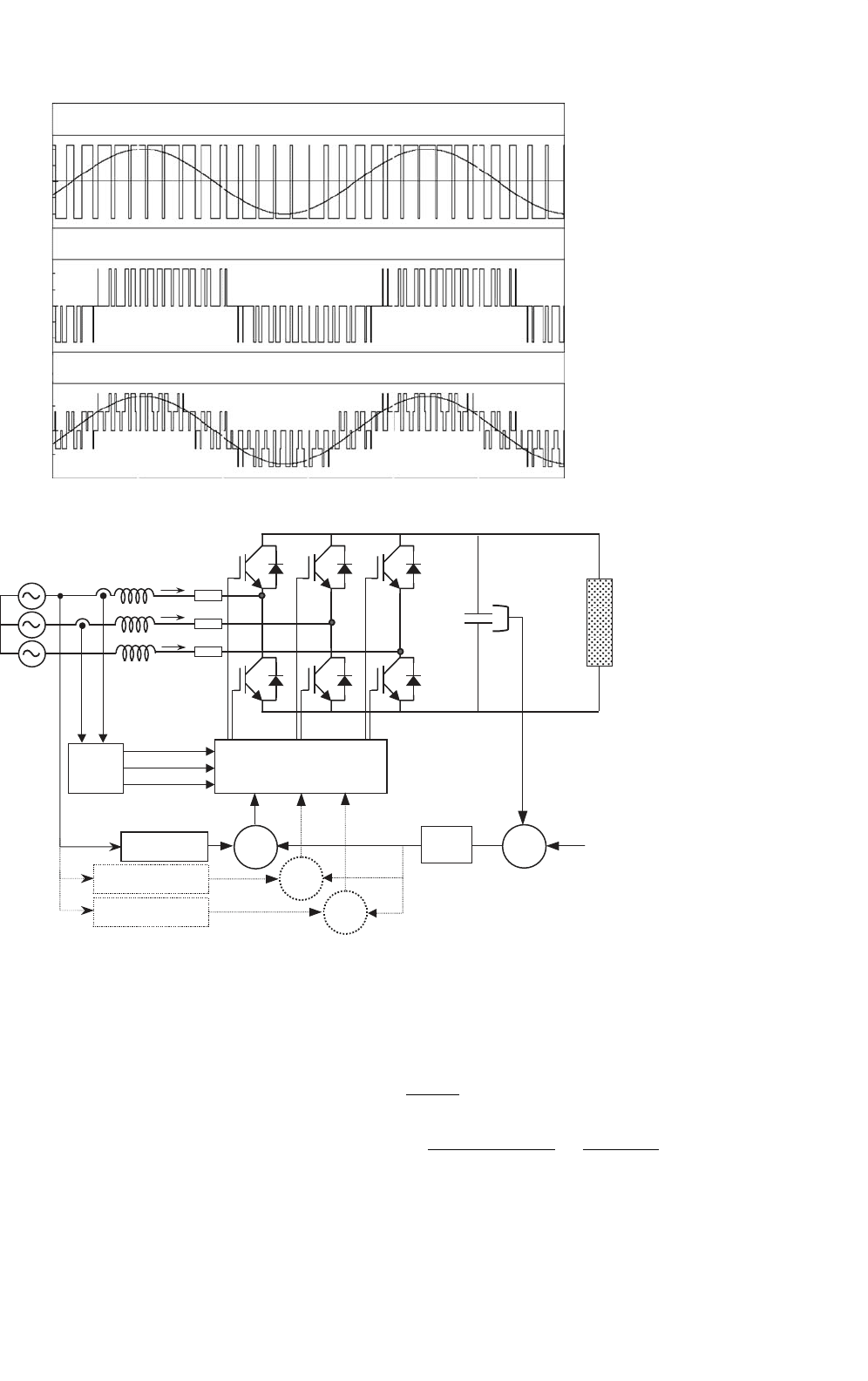
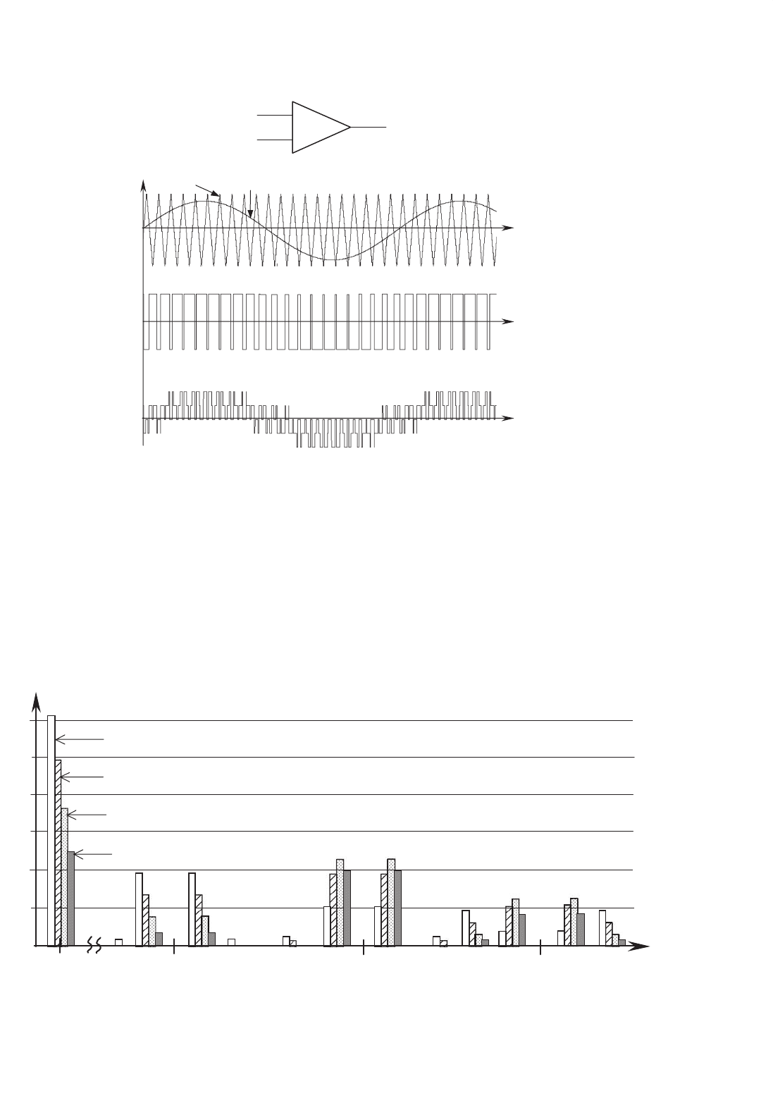
FIGURE 12.42 PWM phase voltages: (a) PWM phase modulation; (b) PWM phase-to-phase voltage; and (c) PWM phase-to-neutral voltage.
PWM generation
e
v
D
+
V
REF
LOAD
Synchr.
G
C
I
MAX
v
B
v
C
sin(wt + j−240°)
sin(wt + j)
sin(wt + j−120°)
i
a,b,c
I_ref
+
_
i
s
A
i
s
B
i
s
C
I_line(a)
I_line(b)
I_line(c)
X
X
X
A B C
L
S
R
v
A
= V
M
sin wt
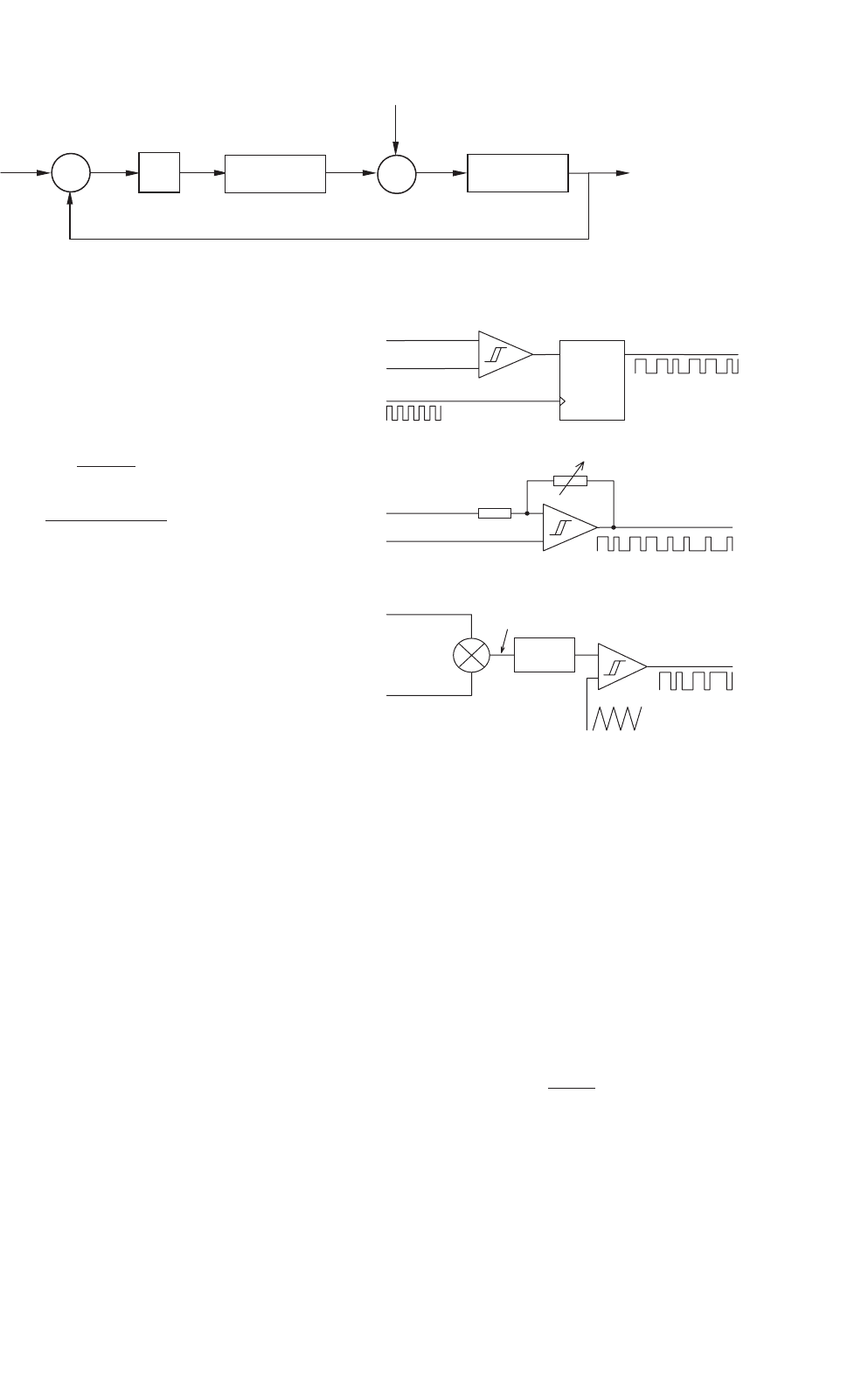
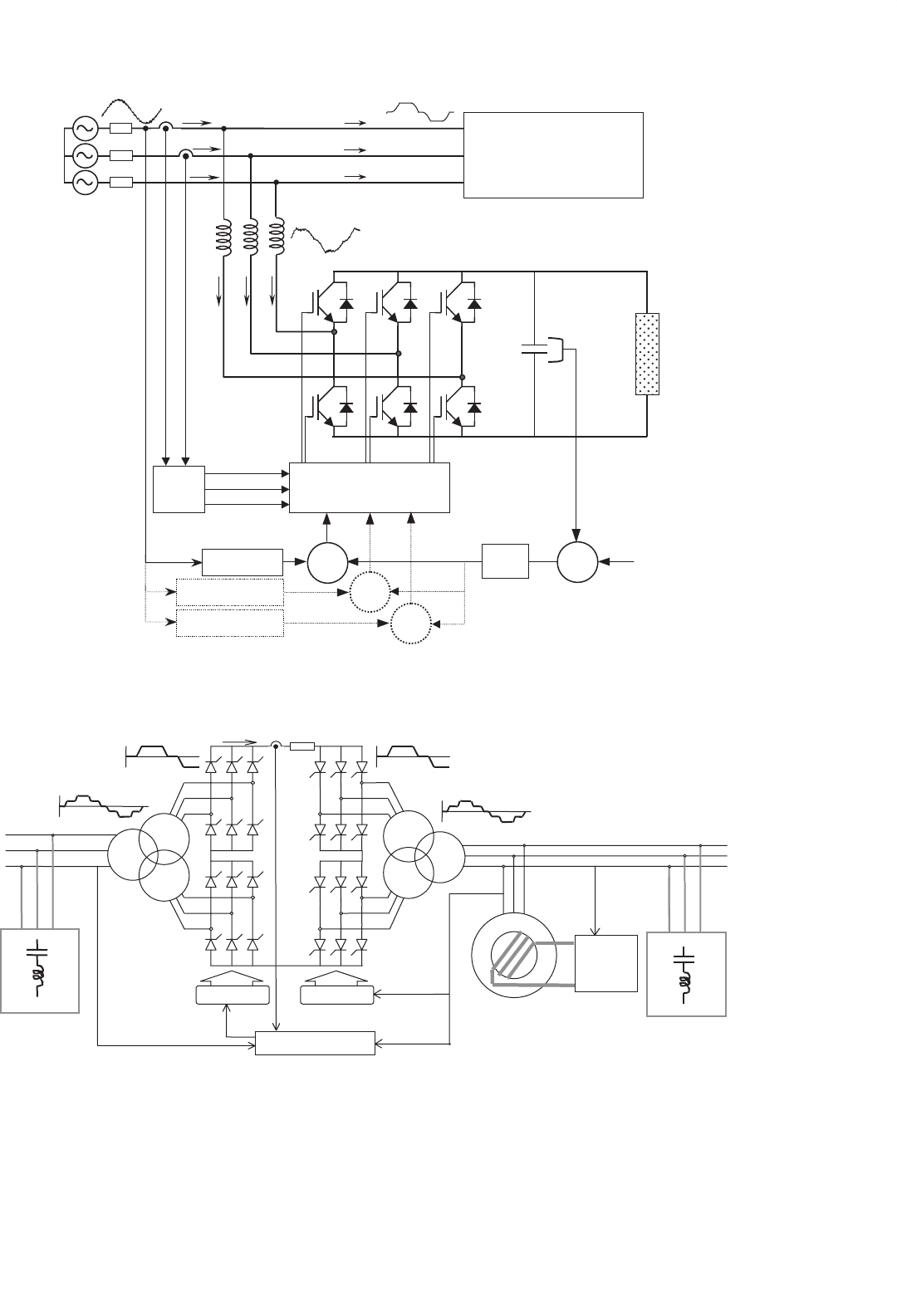
FIGURE 12.43 Voltage-source current-controlled PWM rectifier.
the template has been created and is ready to produce the
PWM pattern.
However, one problem arises with the rectifier because the
feedback control loop on the voltage V
C
can produce instabil-
ity. Then it becomes necessary to analyze this problem during
rectifier design. Upon introducing the voltage feedback and
the G
C
controller, the control of the rectifier can be repre-
sented in a block diagram in Laplace dominion, as shown in
Fig. 12.44. This block diagram represents a linearization of the
system around an operating point, given by the rms value of
the input current, I
S
.
The blocks G
1
(s) and G
2
(s) in Fig. 12.44 represent the trans-
fer function of the rectifier (around the operating point) and
the transfer function of the dc link capacitor C
D
respectively.
G
1
(
s
)
=
P
1
(
s
)
I
S
(
s
)
= 3 ·
(
V cos ϕ −2RI
S
−L
S
I
S
s
)
(12.55)
G
2
(
s
)
=
V
D
(
s
)
P
1
(
s
)
−P
2
(
s
)
=
1
V
D
·C
D
·s
(12.56)
where P
1
(s) and P
2
(s) represent the input and output
power of the rectifier in Laplace dominion, V the rms value of
12 Three-phase Controlled Rectifiers 227
G
C
G
1
(s)
G
2
(s)
DE
DI
S
DP
1
DP
2
DV
REF
DV
D
+
+
–
–
FIGURE 12.44 Closed-loop rectifier transfer function.
the mains voltage supply (phase-to-neutral), I
S
the input cur-
rent being controlled by the template, L
S
the input inductance,
and R the resistance between the converter and power supply.
According to stability criteria, and assuming a PI controller,
the following relations are obtained
I
S
≤
C
D
·V
D
3K
P
·L
S
(12.57)
I
S
≤
K
P
·V ·cos ϕ
2R ·K
P
+L
S
·K
I
(12.58)
These two relations are useful for the design of the current-
controlled rectifier. They relate the values of dc link capacitor,
dc link voltage, rms voltage supply, input resistance and induc-
tance, and input power factor, with the rms value of the input
current, I
S
. With these relations the proportional and integral
gains K
P
and K
I
can be calculated to ensure the stability of
the rectifier. These relations only establish limitations for rec-
tifier operation, because negative currents always satisfy the
inequalities.
With these two stability limits satisfied, the rectifier will keep
the dc capacitor voltage at the value of V
REF
(PI controller),
for all load conditions, by moving power from the ac to the
dc side. Under inverter operation, the power will move in the
opposite direction.
Once the stability problems have been solved and the sinu-
soidal current template has been generated, a modulation
method will be required to produce the PWM pattern for
the power valves. The PWM pattern will switch the power
valves to force the input currents I_line to follow the desired
current template I_ref. There are many modulation meth-
ods in the literature, but three methods for voltage-source
current-controlled rectifiers are the most widely used ones:
periodical sampling (PS), hysteresis band (HB), and triangular
carrier (TC).
The PS method switches the power transistors of the rec-
tifier during the transitions of a square wave clock of fixed
frequency: the periodical sampling frequency. In each tran-
sition, a comparison between I_ref and I_line is made, and
corrections take place. As shown in Fig. 12.45a, this type of
control is very simple to implement: only a comparator and
a D-type flip-flop are needed per phase. The main advantage
of this method is that the minimum time between switching
QD
flip-flop
CLK
+
I_line
I_ref
I_line
I_ref
I_line
I_ref
PWM
sampling clock
–
hysteresis band adjust
PWM
kp + ki/s
+
–
PWM
V_tri
I_err
(a)
(b)
(c)
+
–
+
–
FIGURE 12.45 Modulation control methods: (a) periodical sampling;
(b) hysteresis band; and (c) triangular carrier.
transitions is limited to the period of the sampling clock. This
characteristic determines the maximum switching frequency
of the converter. However, the average switching frequency is
not clearly defined.
The HB method switches the transistors when the error
between I_ref and I_line exceeds a fixed magnitude: the hys-
teresis band. As it can be seen in Fig. 12.45b, this type of
control needs a single comparator with hysteresis per phase.
In this case the switching frequency is not determined, but
its maximum value can be evaluated through the following
equation
f
max
S
=
V
D
4h ·L
S
(12.59)
where h is the magnitude of the hysteresis band.
The TC method, shown in Fig. 12.45c, compares the
error between I_ref and I_line with a triangular wave. This
triangular wave has fixed amplitude and frequency and is
called the triangular carrier. The error is processed through a
228 J. W. Dixon
proportional-integral (PI) gain stage before comparison with
the TC takes place. As can be seen, this control scheme is more
complex than PS and HB. The values for k
p
and k
i
deter-
mine the transient response and steady-state error of the TC
method. It has been found empirically that the values for k
p
and k
i
shown in Eqs. (12.60) and (12.61) give a good dynamic
performance under several operating conditions.
k
p
=
L
s
·ω
c
2 ·V
D
(12.60)
k
i
= ω
c
·K
P
(12.61)
where L
S
is the total series inductance seen by the rectifier,
ω
c
is the TC frequency, and V
D
is the dc link voltage of the
rectifier.
In order to measure the level of distortion (or undesired har-
monic generation) introduced by these three control methods,
Eq. (12.62) is defined
%Distortion =
100
I
rms
1
T
T
(I_line −I_ref )
2
dt (12.62)
In Eq. (12.62), the term I
rms
is the effective value of the
desired current. The term inside the square root gives the rms
value of the error current, which is undesired. This formula
measures the percentage of error (or distortion) of the gener-
ated waveform. This definition considers the ripple, amplitude,
and phase errors of the measured waveform, as opposed to the
THD, which does not take into account offsets, scalings, and
phase shifts.
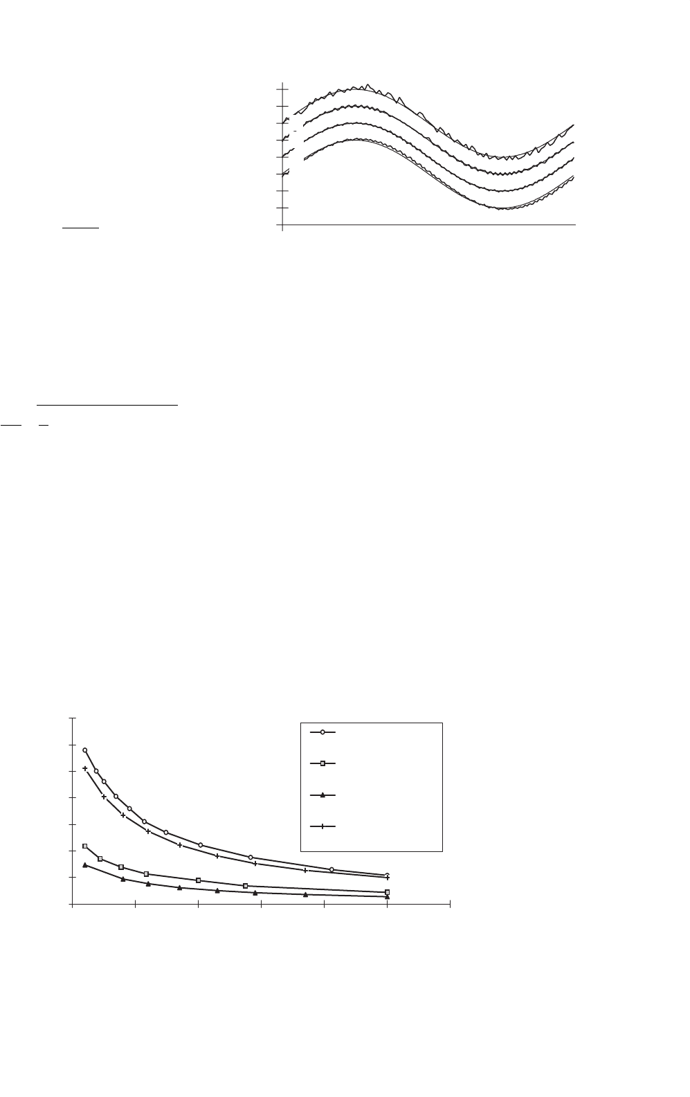
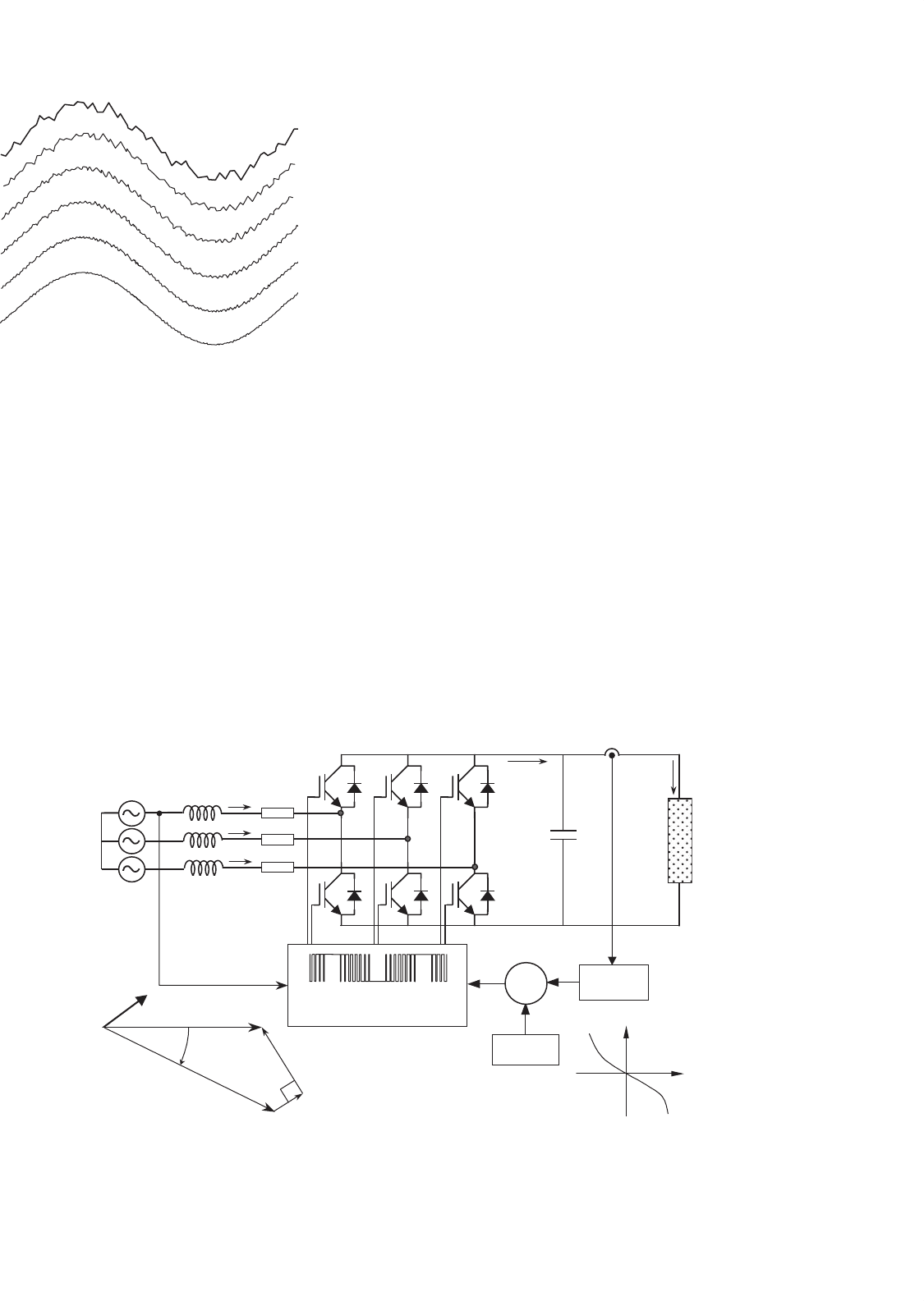
Figure 12.46 shows the current waveforms generated by the
three aforementioned methods. The example uses an aver-
age switching frequency of 1.5 kHz. The PS is the worst, but
its digital implementation is simpler. The HB method and TC
0
2
4
6
8
10
12
14
1000 2000 3000 4000 5000 6000 700
0
Switchin
g
Fre
q
uenc
y
(
Hz
)
% Distortion
Periodical Sampling
Hysteresis Band
Triangular Carrier
(K
P
*+K
I
*)
Triangular Carrier
(only K
P
*)
FIGURE 12.47 Distortion comparison for a sinusoidal current reference.
(a)
(b)
(c)
(d)
FIGURE 12.46 Waveforms obtained using 1.5 kHz switching frequency
and L
S
= 13 mH: (a) PS method; (b) HB method; (c) TC method (K
P
+
K
I
); and (d) TC method (K
P
only).
with PI control are quite similar, and the TC with only propor-
tional control gives a current with a small phase shift. However,
Fig. 12.47 shows that the higher the switching frequency, the
closer the results obtained with the different modulation meth-
ods. Over 6 kHz of switching frequency, the distortion is very
small for all methods.
12.3.4.2 Voltage-source Voltage-controlled PWM
Rectifier
Figure 12.48 shows a one-phase diagram from which the con-
trol system for a voltage-source voltage-controlled rectifier is
derived. This diagram represents an equivalent circuit of the
fundamentals, that is, pure sinusoidal at the mains side and
pure dc at the dc link side. The control is achieved by creat-
ing a sinusoidal voltage template V
MOD
, which is modified in
amplitude and angle to interact with the mains voltage V.In
this way the input currents are controlled without measuring
them. The template V
MOD
is generated using the differential
equations that govern the rectifier.

12 Three-phase Controlled Rectifiers 229
+
LOAD
V
D
i
dc
C
D
I
D
L
S
R
i
s
(t)
v
MOD
(t)
v(t)
ac-dc
conversion
SOURCE RECTIFIER LOAD
FIGURE 12.48 One-phase fundamental diagram of the voltage source rectifier.
The following differential equation can be derived from
Fig. 12.48
v(t ) = L
S
di
s
dt
+Ri
s
+v
MOD
(t) (12.63)
Assuming that v(t) = V
√
2 sin ωt , then the solution for
i
s
(t), to acquire a template V
MOD
able to make the rectifier
work at constant power factor, should be of the form
i
s
(t) = I
max
(t) sin(ωt +ϕ) (12.64)
Equations (12.63), (12.64), and v(t) allows a function of
time able to modify V
MOD
in amplitude and phase that will
make the rectifier work at a fixed power factor. Combining
these equations with v(t) yields
v
MOD
(t) =
V
√
2 +X
S
I
max
sin ϕ −
RI
max
+L
S
dI
max
dt
cos ϕ
sin ωt
−
X
S
I
max
cos ϕ +
RI
max
+L
S
dI
max
dt
sin ϕ
cos ωt
(12.65)
Equation (12.65) provides a template for V
MOD
, which is
controlled through variations of the input current amplitude
I
max
. Substituting the derivatives of I
max
into Eq. (12.65) make
sense, because I
max
changes every time the dc load is modified.
The term X
S
in Eq. (12.65) is ωL
S
. This equation can also
be written for unity power factor operation. In such a case,
cos ϕ = 1 and sin ϕ = 0.
v
MOD
(t) =
V
√
2 −RI
max
−L
S
dI
max
dt
sin ωt
−X
S
I
max
cos ωt (12.66)
With this last equation, a unity power factor, voltage
source, voltage-controlled PWM rectifier can be implemented
as shown in Fig. 12.49. It can be observed that Eqs. (12.65) and
(12.66) have an in-phase term with the mains supply (sin ωt)
and an in-quadrature term (cos ωt). These two terms allow
the template V
MOD
to change in magnitude and phase so as to
have full unity power factor control of the rectifier.
Compared with the control block of Fig. 12.43, in the
voltage-source voltage-controlled rectifier of Fig. 12.49, there
is no need to sense the input currents. However, to ensure
stability limits as good as the limits of the current-controlled
rectifier, the blocks “–R–sL
S
” and “–X
S
” in Fig. 12.49, have to
emulate and reproduce exactly the real values of R, X
S
, and
L
S
of the power circuit. However, these parameters do not
remain constant, and this fact affects the stability of this sys-
tem, making it less stable than the system showed in Fig. 12.43.
In theory, if the impedance parameters are reproduced exactly,
the stability limits of this rectifier are given by the same
equations as used for the current-controlled rectifier seen in
Fig. 12.43 (Eqs. (12.57) and (12.58)).
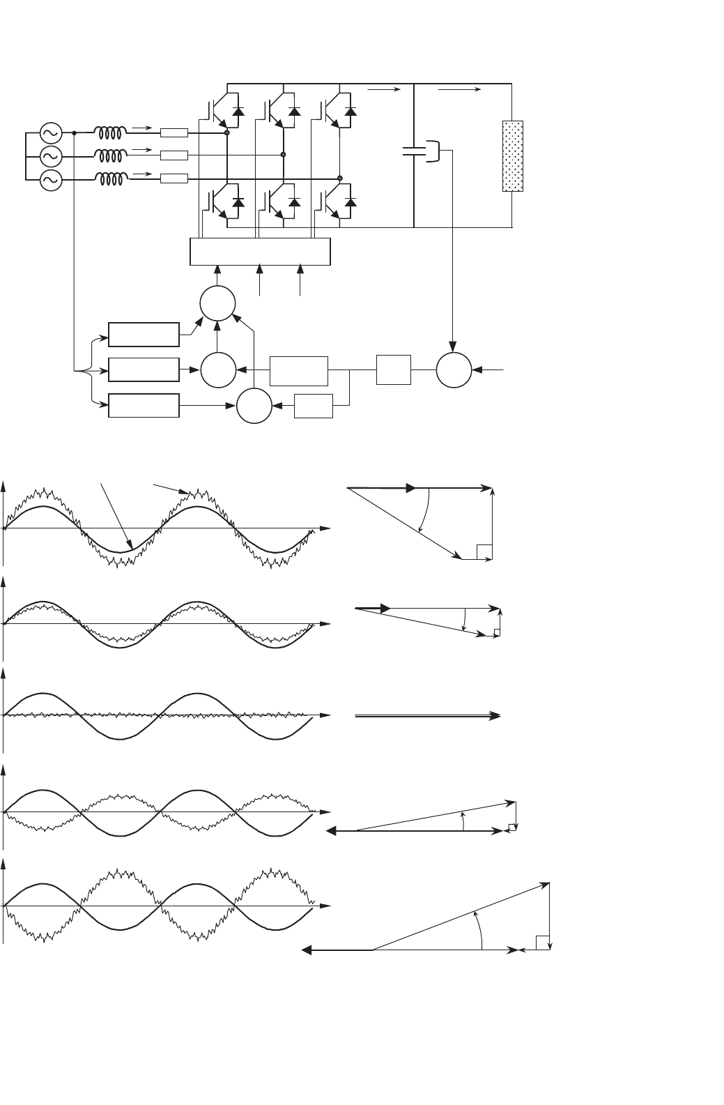
Under steady-state, I
max
is constant, and Eq. (12.66) can be
written in terms of phasor diagram, resulting in Eq. (12.67).
As shown in Fig. 12.50, different operating conditions for the
unity power factor rectifier can be displayed with this equation
V
MOD
=
V −R
I
S
−jX
S
I
S
(12.67)
With the sinusoidal template V
MOD
already created, a
modulation method to commutate the transistors will be
required. As in the case of current-controlled rectifier, there
are many methods to modulate the template, with the most
well known the so-called sinusoidal pulse width modulation
(SPWM), which uses a TC to generate the PWM as shown in
Fig. 12.51. Only this method will be described in this chapter.
In this method, there are two important parameters to
define: the amplitude modulation ratio or modulation index
m, and the frequency modulation ratio p. Definitions are
given by
m =
V
max
MOD
V
max
TRIANG
(12.68)
p =
f
T
f
S
(12.69)
where V
max
MOD
and V
max
TRIANG
are the amplitudes of V
MOD
and
V
TRIANG
respectively. On the other hand, f
S
is the frequency of
230 J. W. Dixon
PWM generation
e
V
D
+
V
REF
LOAD
Synchr.
G
C
I
max
v
A
= V
M
sin ωt
v
B
v
C
cos(wt)
+
_
i
s
C
i
s
B
i
s
A
X
–X
s
–R–sL
s
X
+
sin(wt)
V
M
sin(wt)
v
MOD
A
v
MOD
B
v
MOD
C
i
dc
I
D
L
S
R
FIGURE 12.49 Implementation of the voltage-controlled rectifier for unity power factor operation.
I
S
= 0 V
V
MOD
VI
S
I
S
V
V
MOD
jwL
S
I
S
jwL
S
I
S
RI
S
I
S
V
V
MOD
RI
S
I
S
V
V
MOD
jwL
S
I
S
jwL
S
I
S
I
S
V
V
MOD
RI
S
RI
S
δ
δ
δ
δ
FIGURE 12.50 Steady-state operation of the unity power factor rectifier under different load conditions.
12 Three-phase Controlled Rectifiers 231
V
PWM
A
V
PWM
AN
V
TRIANG
V
MOD
A
V
MOD
A
COMPARATOR
V
PWM
A
V
TRIANG
+
–
FIGURE 12.51 Sinusoidal modulation method based on TC.
the mains supply and f
T
the frequency of the TC. In Fig. 12.51,
m = 0.8 and p = 21. When m > 1 overmodulation is defined.
The modulation method described in Fig. 12.51 has a har-
monic content that changes with p and m. When p < 21, it is
recommended that synchronous PWM be used, which means
that the TC and the template should be synchronized. Further-
more, to avoid subharmonics, it is also desired that p be an
V
f-f
rms
/V
D
0.1
0.6
0.5
0.4
0.3
0.2
m = 1
m = 0.8
1
p − 4p − 2
p
p + 2 p + 4 2p − 5 2p − 1
2p
2p + 1 2p + 5 3p − 4 3p − 2
3p
3p + 2 3p + 4
m = 0.6
m = 0.4
FIGURE 12.52 Harmonic spectrum for SPWM modulation.
integer. If p is an odd number, even harmonics will be elimi-
nated. If p is a multiple of 3, then the PWM modulation of the
three phases will be identical. When m increases, the ampli-
tude of the fundamental voltage increases proportionally, but
some harmonics decrease. Under overmodulation (m > 1),
the fundamental voltage does not increase linearly, and more
harmonics appear. Figure 12.52 shows the harmonic spectrum
232 J. W. Dixon
P=9
P=15
P= 21
P= 27
P= 39
P=81
FIGURE 12.53 Current waveforms for different values of p.
of the three-phase PWM voltage waveforms for different values
of m, and p = 3k where k is an odd number.
Due to the presence of the input inductance L
S
, the har-
monic currents that result are proportionally attenuated with
the harmonic number. This characteristic is shown in the cur-
rent waveforms of Fig. 12.53, where larger p numbers generate
cleaner currents. The rectifier that originated the currents of
Fig. 12.53 has the following characteristics: V
D
= 450 V
dc
,
V
rms
f −f
= 220 V
ac
, L
S
= 2 mH, and input current I
S
= 80 A
rms
.
It can be observed that with p > 21 the current distortion
is quite small. The value of p = 81 in Fig. 12.53 produces
an almost pure sinusoidal waveform, and it means 4860 Hz
V
D
+
LOAD
Synchr.
v
A
= V
M
sin wt
v
B
v
C
+
_
i
s
B
i
s
C
d=f(Id)
i
s
A
i
dc
I
D
L
S
R
DIGITAL CONTROL WITH
FIXED PWM PATTERN
δ
OFFSET
I
S
V
V
MOD
jwL
S
I
S
RI
S
I
D
d
d
FIGURE 12.54 Voltage-source load-controlled PWM rectifier.
of switching frequency at 60 Hz or only 4.050 Hz in a rectifier
operating in a 50 Hz supply. This switching frequency can be
managed by MOSFETs, IGBTs, and even Power Darlingtons.
Then a number p = 81, is feasible for today’s low and medium
power rectifiers.
12.3.4.3 Voltage-source Load-controlled PWM
Rectifier
A simple method of control for small PWM rectifiers (up
to 10–20 kW) is based on direct control of the dc current.
Figure 12.54 shows the schematic of this control system. The
fundamental voltage V
MOD
modulated by the rectifier is pro-
duced by a fixed and unique PWM pattern, which can be
carefully selected to eliminate most undesirable harmonics. As
the PWM does not change, it can be stored in a permanent
digital memory (ROM).
The control is based on changing the power angle δ between
the mains voltage V and fundamental PWM voltage V
MOD
.
When δ changes, the amount of power flow transferred from
the ac to the dc side also changes. When the power angle is
negative (V
MOD
lags V), the power flow goes from the ac to
the dc side. When the power angle is positive, the power flows
in the opposite direction. Then, the power angle can be con-
trolled through the current I
D
. The voltage V
D
does not need
to be sensed, because this control establishes a stable dc volt-
age operation for each dc current and power angle. With these
characteristics, it is possible to find a relation between I
D
and
δ so as to obtain constant dc voltage for all load conditions.

12 Three-phase Controlled Rectifiers 233
This relation is given by
I
D
= f (δ) =
V
cos δ −
ωL
S
R
sin δ −1
R
1 +
ωL
S
R
2
(12.70)
From Eq. (12.70) a plot and a reciprocal function δ = f(I
D
) is
obtained to control the rectifier. The relation between I
D
and δ
allows for leading power factor operation and null regulation.
The leading power factor operation is shown in the phasor
diagram of Fig. 12.54.
The control scheme of the voltage-source load-controlled
rectifier is characterized by the following: (i) there are neither
input current sensors nor dc voltage sensor; (ii) it works with a
fixed and predefined PWM pattern; (iii) it presents very good
stability; (iv) its stability does not depend on the size of the
dc capacitor; (v) it can work at leading power factor for all
load conditions; and (vi) it can be adjusted with Eq. (12.70)
to work at zero regulation. The drawback appears when R
in Eq. (12.70) becomes negligible, because in such a case the
control system is unable to find an equilibrium point for the dc
link voltage. That is why this control method is not applicable
to large systems.
12.3.5 New Technologies and Applications of
Force-commutated Rectifiers
The additional advantages of force-commutated rectifiers
with respect to line-commutated rectifiers, make them bet-
ter candidates for industrial requirements. They permit new
applications such as rectifiers with harmonic elimination capa-
bility (active filters), power factor compensators, machine
drives with four-quadrant operation, frequency links to con-
nect 50 Hz with 60 Hz systems, and regenerative converters for
traction power supplies. Modulation with very fast valves such
as IGBTs permit almost sinusoidal currents to be obtained.
The dynamics of these rectifiers is so fast that they can reverse
power almost instantaneously. In machine drives, current
source PWM rectifiers, like the one shown in Fig. 12.35a,
can be used to drive dc machines from the three-phase sup-
ply. Four-quadrant applications using voltage-source PWM
rectifiers, are extended for induction machines, synchronous
machines with starting control, and special machines such as
brushless-dc motors. Back-to-back systems are being used in
Japan to link power systems with different frequencies.
12.3.5.1 Active Power Filter
Force-commutated PWM rectifiers can work as active power
filters. The voltage-source current-controlled rectifier has the
capability to eliminate harmonics produced by other polluting
loads. It only needs to be connected as shown in Fig. 12.55.
The current sensors are located at the input terminals of the
power source and these currents (instead of the rectifier cur-
rents) are forced to be sinusoidal. As there are polluting loads
in the system, the rectifier is forced to deliver the harmonics
that loads need, because the current sensors do not allow the
harmonics going to the mains. As a result, the rectifier cur-
rents become distorted, but an adequate dc capacitor C
D
can
keep the dc link voltage in good shape. In this way the rectifier
can do its duty, and also eliminate harmonics to the source. In
addition, it also can compensate power factor and unbalanced
load problems.
12.3.5.2 Frequency Link Systems
Frequency link systems permit power to be transferred form
one frequency to another one. They are also useful for linking
unsynchronized networks. Line-commutated converters are
widely used for this application, but they have some drawbacks
that force-commutated converters can eliminate. For example,
the harmonic filters requirement, the poor power factor, and
the necessity to count with a synchronous compensator when
generating machines at the load side are absent. Figure 12.56
shows a typical line-commutated system in which a 60 Hz load
is fed by a 50 Hz supply. As the 60 Hz side needs excitation to
commutate the valves, a synchronous compensator has been
required.
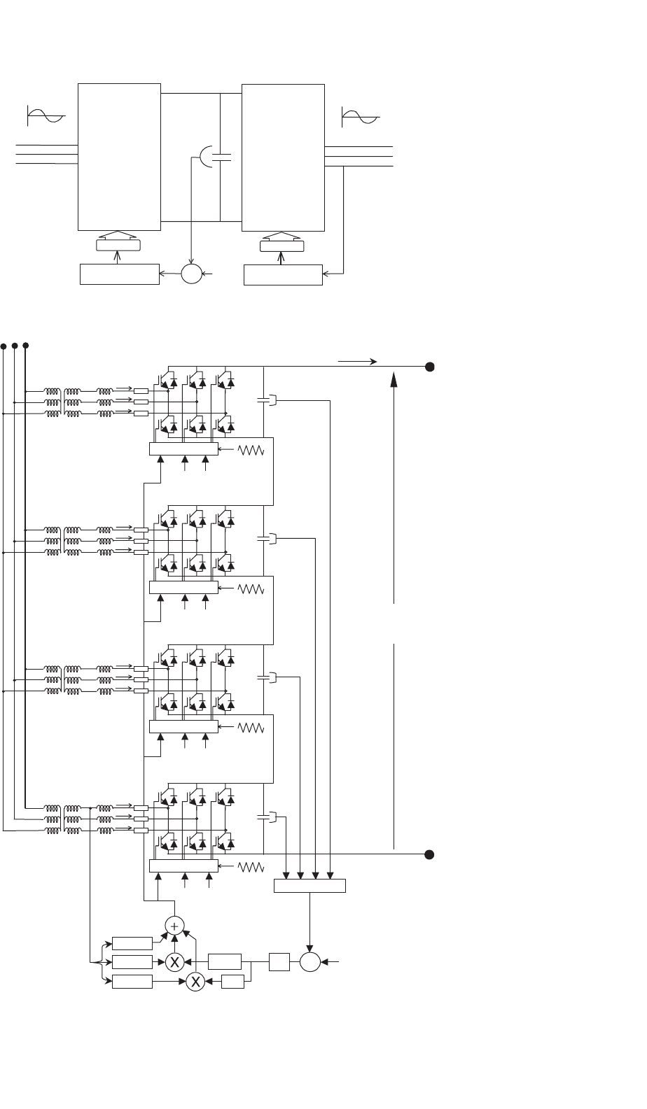
In contrast, an equivalent system with force-commutated
converters is simpler, cleaner, and more reliable. It is imple-
mented with a dc voltage-controlled rectifier, and another
identical converter working in the inversion mode. The power
factor can be adjusted independently at the two ac ter-
minals, and filters or synchronous compensators are not
required. Figure 12.57 shows a frequency link system with
force-commutated converters.
12.3.5.3 Special Topologies for High
Power Applications
High power applications require series- and/or parallel-
connected rectifiers. Series and parallel operation with force-
commutated rectifiers allow improving the power quality
because harmonic cancellation can be applied to these
topologies. Figure 12.58 shows a series connection of force-
commutated rectifiers, where the modulating carriers of the
valves in each bridge are shifted to cancel harmonics. The
example uses sinusoidal PWM that are with TC shifted.
The waveforms of the input currents for the series connec-
tion system are shown in Fig. 12.59. The frequency modulation
ratio shown in this figure is for p = 9. The carriers are shifted
by 90
◦
each, to obtain harmonics cancellation. Shifting of the
carriers δ
T
depends on the number of converters in series (or
in parallel), and is given by
δ
T
=
2π
n
(12.71)
234 J. W. Dixon
PWM generation
e
+
V
REF
LOAD
Synchr.
G
C
I
MAX
sin(wt + j)
sin(wt + j−120°)
sin(wt + j−240°)
i
a,b,c
I_ref
+
_
i
L
A
i
L
B
I_line(a)
I_line(c)
I_line(b)
X
X
X
AC
L
f
POLLUTING LOADS
I_line(a)
I_line(b)
i
L
C
i
f
C
i
f
B
i
f
A
C
D
V
D
B
FIGURE 12.55 Voltage-source rectifier with harmonic elimination capability.
∆
∆
∆
∆
Y
Y
50 Hz
60 Hz
Excitation
Voltage
E
gg
γ controlα control
Master Control
Synchronous
Compensator
L
D
I
D
Passive Filter
Passive Filter
synchr.
FIGURE 12.56 Frequency link systems with line-commutated converters.
12 Three-phase Controlled Rectifiers 235
50 Hz 60 Hz
PWM
CONVERTER
PWM
DC LINK VOLTAGE
CONTROL
CONVERTER
PWM
PWM
POWER CONTROL
60 Hz50 Hz
+
−
V
D
REF
V
D
+
−
FIGURE 12.57 Frequency link systems with force-commutated converters.
I
MAX
V
REF
G
C
-R-sL
s
-X
s
V
M
sin(ωt)
sin(ωt)
cos(ωt)
−
+
v
MOD
A
v
MOD
B
v
MOD
C
v
MOD
A
v
MOD
B
v
MOD
C
v
MOD
A
v
MOD
B
v
MOD
C
v
MOD
A
v
MOD
B
v
MOD
C
V
D(M)
SPWM generation
V
D(3)
SPWM generation
V
D(1)
SPWM generation
V
D(2)
SPWM generation
MONITOR
V
T(2)
V
T(1)
V
T(4)
V
T(3)
I
D
MAINS SUPPLY
V
D
V
D
FIGURE 12.58 Series connection system with force-commutated rectifiers.