Power electronic handbook
Подождите немного. Документ загружается.

10 Diode Rectifiers 175
V
IN
= 60 V
C
L
= 100 µF
L
P
= 100 µH
L
S
= 400 µH
R
L
= 400 W
N
P
: N
S
= 1 : 2
Pulse
3
9
1
0
6
5
0
D
R
C
L
R
L
V
IN
L
P
N
P
L
S
N
S
M
1
T
1
V
o
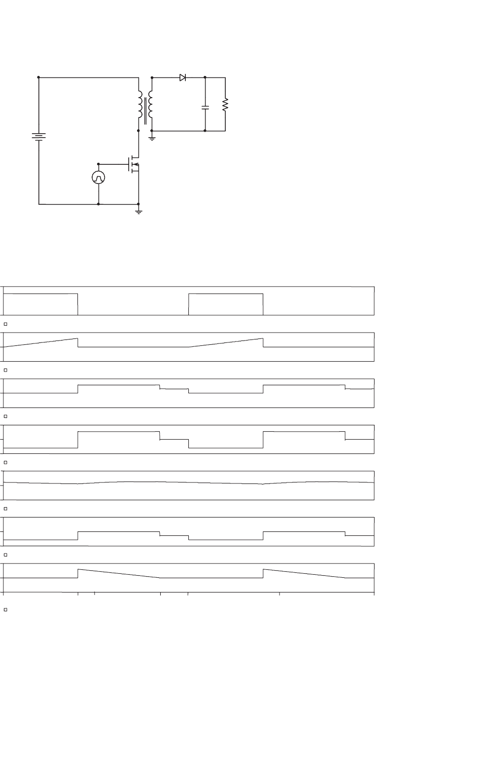
FIGURE 10.38 Basic circuit of flyback converter.
I(DR) or I(LS)
–2.0A
0A
2.0A
V(6,9)
–400V
0V
400V
V(9)
109.0V
109.1V
V(6)
–200V
0V
200V
V(3)
–200V
0V
200V
ID(M1)
–4.0A
0A
4.0A
V1(VPULSE)
0V
20V
Time
0s
4us
DT
5us
10us
T
15us 20us
ON OFF ON OFF
DT T
(D+D
2
)T
109.2V
FIGURE 10.39 Idealized steady-state waveforms of flyback converter for discontinuous-mode operation.
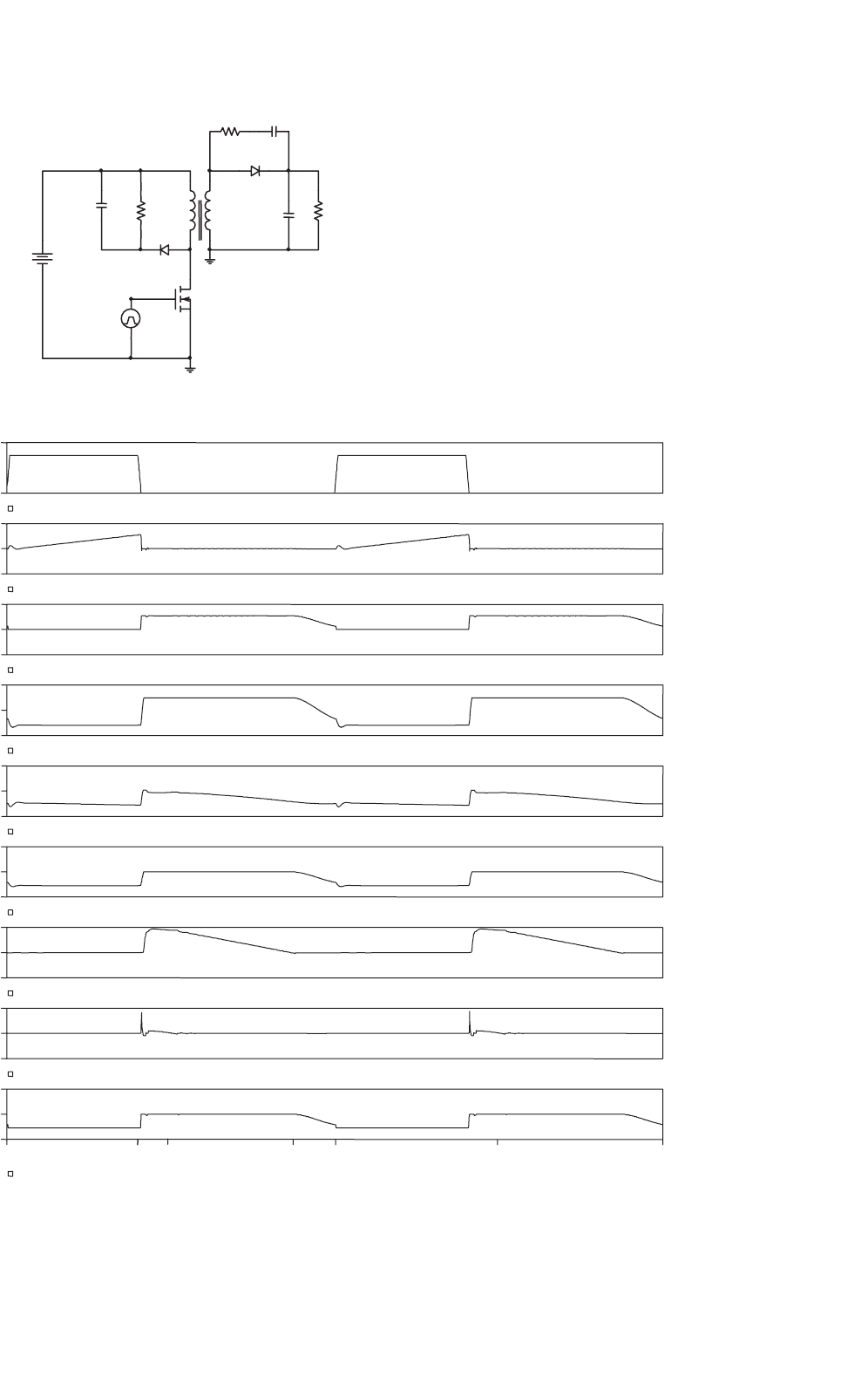
176 Y. S. Lee and M. H. L. Chow
V
IN
= 60 V, D
S
= MUR460
D
R
= MUR460,M
1
= IRF640
R
1
= 4.7 kW, R
2
= 100 W
C
1
= 0.1 mF, C
2
= 680 pF
C
L
= 100 mF, ESR of C
L
= 0.05 W
L
P
= 100 mH, L
S
= 400 mH
R
L
= 400 W
N
P
: N
S
= 1 : 2
Effective winding resistance of L
P
= 0.025 W
Effective winding resistance of L
S
= 0.1 W
Coupling coefficient K = 0.992
Pulse
5
D
R
C
1
0
V
IN
R
L
D
S
C
L
R
1
1
L
S
N
S
6
0
3
9
M
1
L
p
N
p
T
1
2
C
2
R
2
V
o
FIGURE 10.40 Practical flyback converter circuit.
V(3,2)
–200V
0V
200V
I(DS)
–2.0A
0A
2.0A
I(DR)
–1.0A
0A
1.0A
V(6,9)
–400V
0V
400V
V(9)
98.6V
98.7V
V(6)
–200V
0V
200V
V(3)
–200V
0V
200V
ID(M1)
–4.0A
0A
4.0A
V1(VPULSE)
0V
20V
Time
0s
4us
DT
5us
10us
T
15us 20us
ON OFF ON OFF
DT T
(D+D
2
)T
98.8V
FIGURE 10.41 Waveforms of practical flyback converter for discontinuous-mode operation.

10 Diode Rectifiers 177
“Practical circuit” are much more useful for the determina-
tion of the voltage and current ratings of the high-frequency
rectifier diodes.
Assuming that the voltage and current ratings have been
determined, proper diodes can be selected to meet the require-
ments. The following are some general guidelines on the
selection of diodes:
• For low-voltage applications, Schottky diodes should be
used because they have very fast switching speed and low
forward voltage drop. If Schottky diodes cannot be used,
either because of their low reverse breakdown voltage
or because of their large leakage current (when reversely
biased), ultra-fast diodes should be used.
• The reverse breakdown-voltage rating of the diode should
be reasonably higher (e.g. 10 or 20% higher) than
the maximum reverse voltage, the diode is expected to
encounter under the worst-case condition. However, an
overly-conservative design (using a diode with much
higher breakdown voltage than necessary) would result
in a lower rectifier efficiency, because a diode having
a higher reverse-voltage rating would normally have a
larger voltage drop when it is conducting.
• The current rating of the diode should be substan-
tially higher than the maximum current the diode is
expected to carry during normal operation. Using a diode
with a relatively large current rating has the following
advantages:
• It reduces the possibility of damage due to tran-
sients caused by start-up, accidental short circuit, or
random turning on and off of the converter.
• It reduces the forward voltage drop because the diode
is operated in the lower current region of the V–I
characteristic.
In some of the “high-efficiency” converter circuits, the cur-
rent rating of the output rectifier can be many times larger
than the actual current expected in the rectifier. In this way, a
higher efficiency is achieved at the expense of a larger silicon
area.
In the design of R–C snubber circuits for rectifiers, it should
be understood that a larger C (and a smaller R) will give
better damping. However, a large C (and a small R) will result
in a large switching loss (which is equal to 0.5CV
2
f ). As
a guideline, a capacitor with five to ten times the junction
capacitance of the rectifier may be used as a starting point
for iterations. The value of the resistor should be chosen to
provide a slightly underdamped operating condition.
10.6.4 Precautions in Interpreting Simulation
Results
In using the simulated waveforms as references for design
purposes, attention should be paid to the following:
•
The voltage/current spikes that appear in the practically
measured waveforms may not appear in the simulated
waveforms. This is due to the lack of a model in the com-
puter simulation to simulate unwanted coupling among
the practical components.
• Most of the computer models of diodes, including those
used in the simulations given above, do not take into
account the effects of the forward recovery time. (The
forward recovery time is not even mentioned in most
manufacturers’ data sheets.) However, it is also interest-
ing to note that in most cases the effect of the forward
recovery time of a diode is masked by that of the effec-
tive inductance in series with the diode (e.g. the leakage
inductance of a transformer).
Further Reading
1. Rectifier Applications Handbook, 3rd ed., Phoenix, Ariz.: Motorola, Inc.,
1993.
2. M. H. Rashid, Power Electronics: Circuits, Devices, and Applications, 2nd
ed., Englewood Cliffs, NJ: Prentice Hall, Inc., 1993.
3. Y.-S. Lee, Computer-Aided Analysis and Design of Switch-Mode Power
Supplies, New York: Marcel Dekker, Inc., 1993.
4. J. W. Nilsson, Introduction to PSpice Manual, Electric Circuits Using
OrCAD Release 9.1, 4th ed., Upper Saddle River, NJ: Prentice Hall,
Inc., 2000.
5. J. Keown, OrCAD PSpice and Circuit Analysis, 4th ed., Upper Saddle
River, NJ: Prentice Hall, Inc., 2001.

11
Single-phase Controlled Rectifiers
José Rodríguez, Ph.D.,
Pablo Lezana, Samir
Kouro, and Alejandro
Weinstein
Department of Electronics,
Universidad Técnica Federico
Santa María, Valparaíso, Chile
11.1 Introduction .......................................................................................... 179
11.2 Line-commutated Single-phase Controlled Rectifiers..................................... 179
11.2.1 Single-phase Half-wave Rectifier • 11.2.2 Bi-phase Half-wave Rectifier
• 11.2.3 Single-phase Bridge Rectifier • 11.2.4 Analysis of the Input Current • 11.2.5 Power
Factor of the Rectifier • 11.2.6 The Commutation of the Thyristors • 11.2.7 Operation in the
Inverting Mode • 11.2.8 Applications
11.3 Unity Power Factor Single-phase Rectifiers .................................................. 188
11.3.1 The Problem of Power Factor in Single-phase Line-commutated Rectifiers
• 11.3.2 Standards for Harmonics in Single-phase Rectifiers • 11.3.3 The Single-phase Boost
Rectifier • 11.3.4 Voltage Doubler PWM Rectifier • 11.3.5 The PWM Rectifier in Bridge
Connection • 11.3.6 Applications of Unity Power Factor Rectifiers
References ............................................................................................. 199
11.1 Introduction
This chapter is dedicated to single-phase controlled rectifiers,
which are used in a wide range of applications. As shown in
Fig. 11.1, single-phase rectifiers can be classified into two big
categories:
(i) Topologies working with low switching frequency,
also known as line commutated or phase controlled
rectifiers.
(ii) Circuits working with high switching frequency, also
known as power factor correctors (PFCs).
Line-commutated rectifiers with diodes, covered in a pre-
vious chapter of this handbook, do not allow the control of
power being converted from ac to dc. This control can be
achieved with the use of thyristors. These controlled rectifiers
are addressed in the first part of this chapter.
In the last years, increasing attention has been paid to the
control of current harmonics present at the input side of the
rectifiers, originating from a very important development in
the so-called PFC. These circuits use power transistors work-
ing with high switching frequency to improve the waveform
quality of the input current, increasing the power factor. High
power factor rectifiers can be classified in regenerative and
non-regenerative topologies and they are covered in the second
part of this chapter.
11.2 Line-commutated Single-phase
Controlled Rectifiers
11.2.1 Single-phase Half-wave Rectifier
The single-phase half-wave rectifier uses a single thyristor to
control the load voltage as shown in Fig. 11.2. The thyristor
will conduct, on-state, when the voltage v
T
is positive and a
firing current pulse i
G
is applied to the gate terminal. The
control of the load voltage is performed by delaying the firing
pulse by an angle α. The firing angle α is measured from the
position where a diode would naturally conduct. In case of
Fig. 11.2 the angle α is measured from the zero-crossing point
of the supply voltage v
s
. The load in Fig. 11.2 is resistive and
therefore the current i
d
has the same waveform of the load
voltage. The thyristor goes to the non-conducting condition,
off-state, when the load voltage, and consequently the current,
reaches a negative value.
The load average voltage is given by
V
dα
=
1
2π
π
α
V
max
sin(ωt)d(ωt) =
V
max
2π
(
1 +cos α
)
(11.1)
where V
max
is the supply peak voltage. Hence, it can be seen
from Eq. (11.1) that changing the firing angle α controls
Copyright © 2007, 2001, Elsevier Inc.
All rights reserved.
179

180 J. Rodríguez et al.
Single Phase
Rectifiers
Line Commutated
Diode Thyristor Non-regenerative Regenerative (AFE)
Power factor
Correction (PFC)
Boost
Others
Bridge
Voltage Doubler
FIGURE 11.1 Single-phase rectifier classification.
i
d
v
d
i
G
ωt
v
s
ωt
i
d
,v
d
v
d
R
O
O
i
d
v
T
v
s
i
G
+
+
_
απ 2π
FIGURE 11.2 Single-thyristor rectifier with resistive load.
both the load average voltage and the amount of transferred
power.
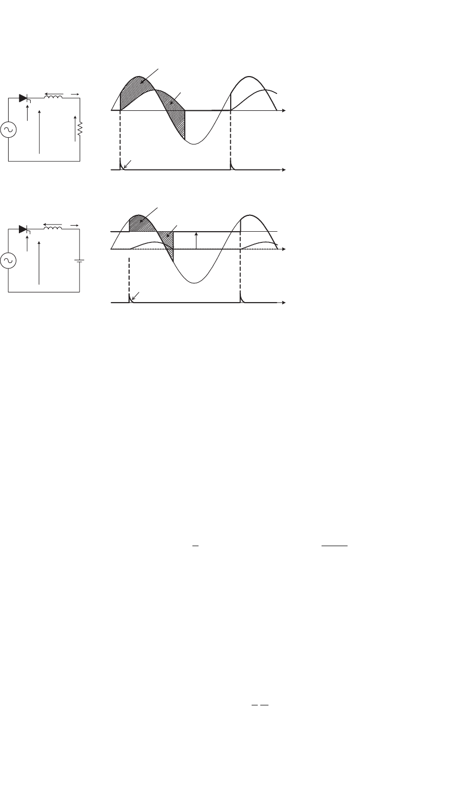
Figure 11.3a shows the rectifier waveforms for an R–L
load. When the thyristor is turned on, the voltage across the
inductance is
v
L
= v
s
−v
R
= L
di
d
dt
(11.2)
where v
R
is the voltage in the resistance R, given by v
R
= R·i
d
.
If v
s
− v
R
> 0, from Eq. (11.2) holds that the load current
increases its value. On the other hand, i
d
decreases its value
when v
s
− v
R
< 0. The load current is given by
i
d
(ωt ) =
1
ωL
ωt
α
v
L
dθ (11.3)
Graphically, Eq. (11.3) means that the load current i
d
is equal
to zero when A
1
=A
2
, maintaining the thyristor in conduction
state even when v
s
< 0.
When an inductive–active load is connected to the rectifier,
as illustrated in Fig. 11.3b, the thyristor will be turned on if the
firing pulse is applied to the gate when v
s
> E
d
. Again, the
thyristor will remain in the on-state until A
1
= A
2
. When
the thyristor is turned off, the load voltage will be v
d
= E
d
.
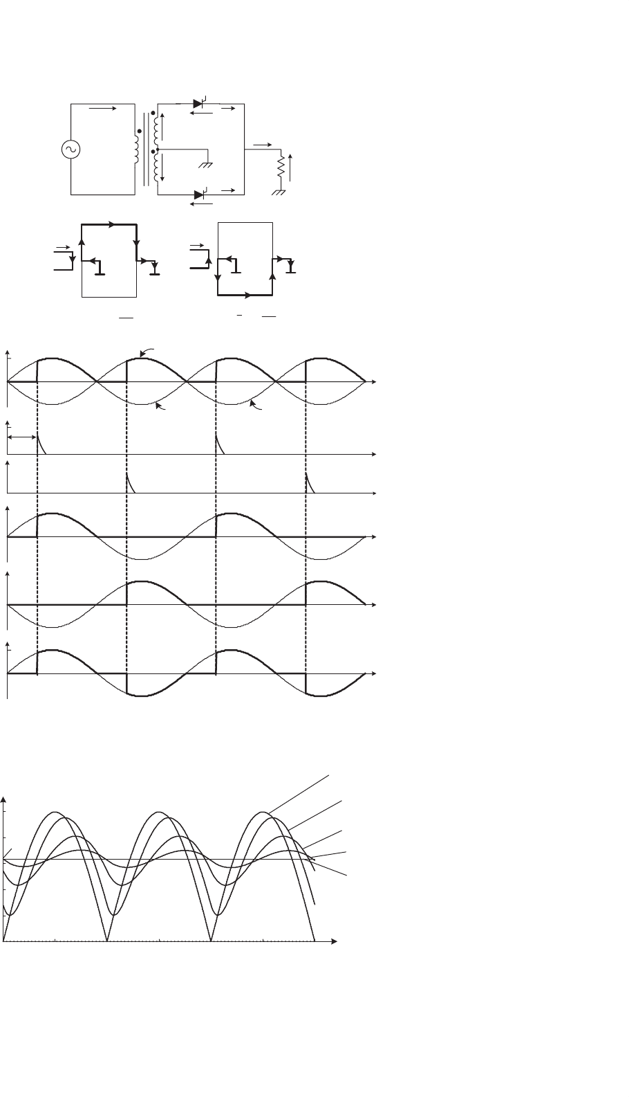
11.2.2 Bi-phase Half-wave Rectifier
The bi-phase half-wave rectifier, shown in Fig. 11.4, uses a
center-tapped transformer to provide two voltages v
1
and v
2
.
These two voltages are 180
◦
out of phase with respect to the
mid-point neutral N. In this scheme, the load is fed via thyris-
tors T
1
and T
2
during each positive cycle of voltages v
1
and v
2
,
respectively, while the load current returns via the neutral N.
As illustrated in Fig. 11.4, thyristor T
1
can be fired into the
on-state at any time while voltage v
T1
> 0. The firing pulses
are delayed by an angle α with respect to the instant where
diodes would conduct. Also the current paths for each con-
duction state are presented in Fig. 11.4. Thyristor T
1
remains
in the on-state until the load current tends to a negative value.
Thyristor T
2
is fired into the on-state when v
T2
> 0, which
corresponds in Fig. 11.4 to the condition when v
2
> 0.
The mean value of the load voltage with resistive load is
determined by
V
diα
=
1
π
π
α
V
max
sin(ωt)d(ωt) =
V
max
π
(1 +cos α)
(11.4)
The ac supply current is equal to i
T1
(N
2
/N
1
) when T
1
is in the
on-state and −i
T2
(N
2
/N
1
) when T
2
is in the on-state, where
N
2
/N
1
is the transformer turns ratio.
11 Single-phase Controlled Rectifiers 181
ωt
ωt
ωt
ωt
v
d
v
R
v
R
,
v
d
v
d
v
d
v
d
v
R
v
d
v
d
v
d
v
d
i
d
i
d
i
d
v
L
v
L
v
s
v
s
v
s
v
s
i
G
i
G
i
G
i
G
+
_
L
E
d
Area A
1
Area A
2
Area A
2
R
+
_
L
+
+
+
E
d
Area A
1
0
0
0
0
2π
2π
(a)
(b)
π
FIGURE 11.3 Single-thyristor rectifier with: (a) resistive-inductive load and (b) active load.
The effect of the load time constant T
L
= L/R, on the
normalized load current i
d
(t)/î
R
(t) for a firing angle α = 0
◦
is
shown in Fig. 11.5. The ripple in the load current reduces as
the load inductance increases. If the load inductance L →∞,
then the current is perfectly filtered.
11.2.3 Single-phase Bridge Rectifier
Figure 11.6a shows a fully controlled bridge rectifier, which
uses four thyristors to control the average load voltage. In
addition, Fig. 11.6b shows the half-controlled bridge rectifier
which uses two thyristors and two diodes.
The voltage and current waveforms of the fully controlled
bridge rectifier for a resistive load are illustrated in Fig 11.7.
Thyristors T
1
and T
2
must be fired on simultaneously dur-
ing the positive half-wave of the source voltage v
s
, to allow
the conduction of current. Alternatively, thyristors T
3
and T
4
must be fired simultaneously during the negative half-wave
of the source voltage. To ensure simultaneous firing, thyris-
tors T
1
and T
2
use the same firing signal. The load voltage
is similar to the voltage obtained with the bi-phase half-wave
rectifier. The input current is given by
i
S
= i
T1
−i
T4
(11.5)
and its waveform is shown in Fig. 11.7.
Figure 11.8 presents the behavior of the fully controlled rec-
tifier with resistive–inductive load (with L →∞). The high
load inductance generates a perfectly filtered current and the
rectifier behaves like a current source. With continuous load
current, thyristors T
1
and T
2
remain in the on-state beyond the
positive half-wave of the source voltage v
s
. For this reason,
the load voltage v
d
can have a negative instantaneous value.
The firing of thyristors T
3
and T
4
has two effects:
(i) they turn-off thyristors T
1
and T
2
and
(ii) after the commutation, they conduct the load current.
This is the main reason why this type of converters are called
“naturally commutated” or “line commutated” rectifiers. The
supply current i
S
has the square waveform, as shown in
Fig. 11.9, for continuous conduction. In this case, the average
load voltage is given by
V
diα
=
1
π
π+α
α
V
max
sin(ωt)d(ωt) =
2V
max
π
cos α (11.6)
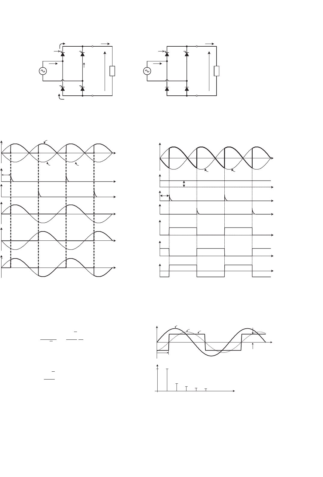
11.2.4 Analysis of the Input Current
Considering a very high inductive load, the input current in
a bridge-controlled rectifier is filtered and presents a square
waveform. In addition, the input current i
s
is shifted by the
firing angle α with respect to the input voltage v
s
, as shown
in Fig. 11.9a. The input current can be expressed as a Fourier
series, where the amplitude of the different harmonics are
I
smax, n
=
4
π
I
d
n
(n = 1, 3, 5, ...) (11.7)
182 J. Rodríguez et al.
i
s
= i
T1
·
R
N
i
s
i
T1
i
g1
i
g2
i
T2
−v
s
v
s
i
s
i
s
i
s
i
d
v
d
v
s
v
1
v
2
v
d
N
1
N
2
i
s
= i
T2
·
N
1
N
2
V
max
α
ωt
ωt
ωt
ωt
ωt
ωt
0
0
0
0
0
0
i
T1
v
T1
i
T2
T
2
T
1
v
T2
N
2
N
1
+
FIGURE 11.4 Bi-phase half-wave rectifier.
î
R
= V
max
IR
i
d
(t)/î
R
T
L
= 0
T
L
= 1 ms
T
L
= 3.2 ms
T
L
= 10 ms
T
L
→ ∞
t
0
0.2
0.4
0.6
0.8
1.0
α = 0°
2/π
FIGURE 11.5 Effect of the load time constant over the current ripple.
11 Single-phase Controlled Rectifiers 183
P
N
P
N
T
1
T
4
T
2
T
3
v
d
i
s
i
d
D
1
T
1
T
2
D
2
i
g1
v
s
v
s
v
d
i
s
i
T3
i
T4
i
d
i
T1
i
g1
Load Load
++
(a) (b)
FIGURE 11.6 Single-phase bridge rectifier: (a) fully controlled and (b) half-controlled.
v
d
i
s
i
T1
, i
T2
i
g1
, i
g2
i
g3
, i
g4
i
T3
, i
T4
V
max
ωt
ωt
ωt
ωt
ωt
ωt
v
s
−v
s
0
0
α
0
0
0
0
FIGURE 11.7 Waveforms of a fully controlled bridge rectifier with
resistive load.
where n is the harmonic order. The root mean square (rms)
value of each harmonic can be expressed as
I
sn
=
I
smax, n
√
2
=
2
√
2
π
I
d
n
(11.8)
Thus, the rms value of the fundamental current i
s1
is
I
s1
=
2
√
2
π
I
d
= 0.9I
d
(11.9)
It can be observed from Fig. 11.9a that the displacement
angle φ
1
of the fundamental current i
s1
corresponds to the
firing angle α. Figure 11.9b shows that in the harmonic spec-
trum of the input current, only odd harmonics are present with
ωt
ωt
ωt
ωt
ωt
ωt
ωt
i
s
i
T1
, i
T2
i
g1
, i
g2
i
g3
, i
g4
i
T3
, i
T4
V
max
i
d
α
v
s
I
d
−v
s
0
0
0
0
0
0
0
FIGURE 11.8 Waveforms of a fully controlled bridge rectifier with
resistive–inductive load (L →∞).
v
s
i
s
i
sn
/i
s1
i
s1
φ
1
= α
I
d
ωt
n
1
1
0
1/3
1/5
1/7
1/9
3579
(a)
(b)
FIGURE 11.9 Input current of the single-phase controlled rectifier in
bridge connection: (a) waveforms and (b) harmonics spectrum.

184 J. Rodríguez et al.
decreasing amplitude while the frequency increases. Finally the
rms value of the input current i
s
is
I
s
= I
d
(11.10)
The total harmonic distortion (THD) of the input current can
be determined by
THD =
I
2
s
−I
2
s1
I
s1
100 = 48.4% (11.11)
11.2.5 Power Factor of the Rectifier
The displacement factor of the fundamental current, obtained
from Fig. 11.9a is
cos φ
1
= cos α (11.12)
In the case of non-sinusoidal currents, the active power
delivered by the sinusoidal single-phase supply is
P =
1
T
T
0
v
s
(t)i
s
(t)dt = V
s
I
s1
cos φ
1
(11.13)
where V
s
is the rms value of the single-phase voltage v
s
.
The apparent power is given by
S = V
s
I
s
(11.14)
The power factor (PF) is defined by
PF =
P
S
(11.15)
Substitution from Eqs. (11.12), (11.13), and (11.14) in
Eq. (11.15) yields
PF =
I
s1
I
s
cos α (11.16)
This equation shows clearly that due to the non-sinusoidal
waveform of the input current, the power factor of the rectifier
is negatively affected both by the firing angle α and by the
distortion of the input current. In effect, an increase in the
distortion of the current produces an increase in the value
of I
s
in Eq. (11.16), which deteriorates the power factor.
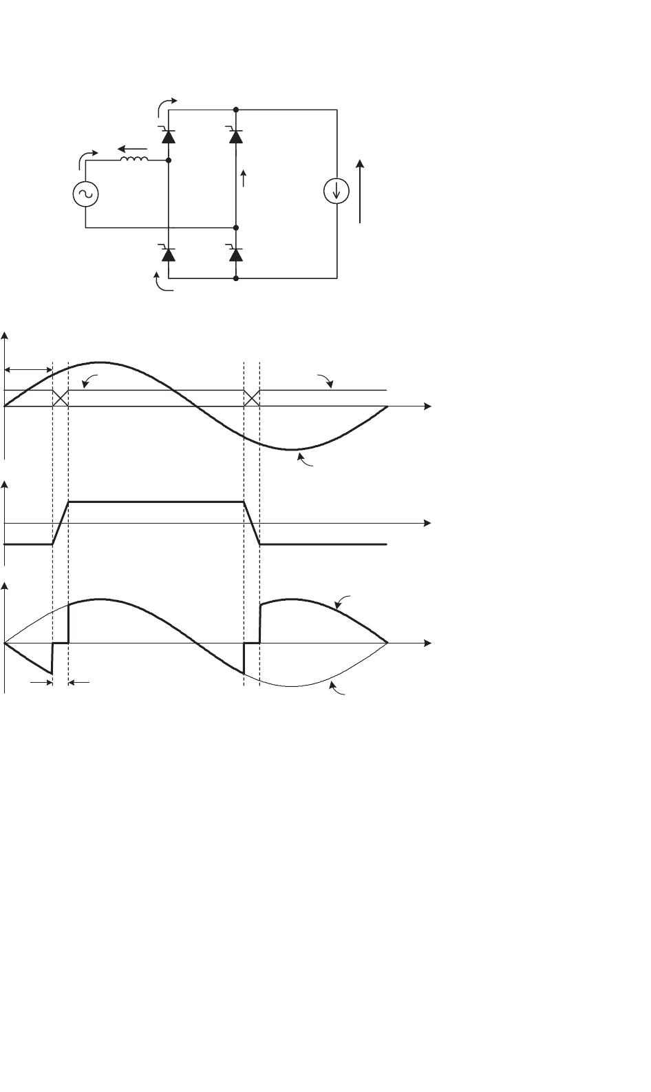
11.2.6 The Commutation of the Thyristors
Until now, the current commutation between thyristors has
been considered to be instantaneous. This condition is not
valid in real cases due to the presence of the line induc-
tance L, as shown in Fig. 11.10a. During the commutation,
the current through the thyristors cannot change instanta-
neously, and for this reason, during the commutation angle µ,
all four thyristors are conducting simultaneously. Therefore,
during the commutation, the following relationship for the
load voltage holds
v
d
= 0 α ≤ ωt ≤ α + µ (11.17)
The effect of the commutation on the supply current, volt-
age waveforms, and the thyristor current waveforms can be
observed in Fig. 11.10b.
During the commutation, the following expression holds
L
di
s
dt
= v
s
= V
max
sin(ωt) α ≤ ωt ≤ α + µ (11.18)
Integrating Eq. (11.18) over the commutation interval yields
I
d
−I
d
di
s
=
V
max
L
α+µ/ω
α/ω
sin(ωt)dt (11.19)
From Eq. (11.19), the following relationship for the commu-
tation angle µ is obtained
cos(α +µ) = cos α −
2ωL
V
max
I
d
(11.20)
Equation (11.20) shows that an increase of the line induc-
tance L or an increase of the load current I
d
increases the
commutation angle µ. In addition, the commutation angle is
affected by the firing angle α. In effect, Eq. (11.18) shows that
with different values of α, the supply voltage v
s
has a different
instantaneous value, which produces different di
s
/dt, thereby
affecting the duration of the commutation.
Equation (11.17) and the waveform of Fig. 11.10b show that
the commutation process reduces the average load voltage V
dα
.
When the commutation is considered, the expression for the
average load voltage is given by
V
dα
=
1
π
π+α
α+µ
sin(ωt)d(ωt) =
V
max
π
[
cos(α +µ) +cos α
]
(11.21)
Substituting Eq. (11.20) into Eq. (11.21) yields
V
dα
=
2
π
V
max
cos α −
2ωL
π
I
d
(11.22)
11 Single-phase Controlled Rectifiers 185
m
0
0
0
wt
wt
wt
i
s
v
s
α
i
T1
v
s
v
d
i
T3
I
d
T
1
i
T3
i
T1
i
T4
v
d
i
s
v
s
+
(b)
L
v
L
(a)
T
3
T
4
T
2
FIGURE 11.10 The commutation process: (a) circuit and (b) waveforms.
11.2.7 Operation in the Inverting Mode
When the angle α>90
◦
, it is possible to obtain a negative aver-
age load voltage. In this condition, the power is fed back to
the single-phase supply from the load. This operating mode
is called inverter or inverting mode, because the energy is
transferred from the dc to the ac side. In practical cases, this
operating mode is obtained when the load configuration is
as shown in Fig. 11.11a. It must be noticed that this rectifier
allows unidirectional load current flow.
Figure 11.11b shows the waveform of the load voltage
with the rectifier in the inverting mode, neglecting the source
inductance L.
Section 11.2.6 described how supply inductance increases
the conduction interval of the thyristors by the angle µ.As
shown in Fig. 11.11c, the thyristor voltage v
T1
has a negative
value during the extinction angle γ, defined by
γ = 180 − (α + µ) (11.23)
To ensure that the outgoing thyristor will recover its blocking
capability after the commutation, the extinction angle should
satisfy the following restriction
γ>ωt
q
(11.24)