Power electronic handbook
Подождите немного. Документ загружается.


10
Diode Rectifiers
Yim-Shu Lee and Martin
H. L. Chow
Department of Electronic and
Information Engineering,
The Hong Kong Polytechnic,
University Hung Hom,
Hong Kong
10.1 Introduction .......................................................................................... 145
10.2 Single-phase Diode Rectifiers .................................................................... 145
10.2.1 Single-phase Half-wave Rectifiers • 10.2.2 Single-phase Full-wave Rectifiers
• 10.2.3 Performance Parameters • 10.2.4 Design Considerations
10.3 Three-phase Diode Rectifiers .................................................................... 150
10.3.1 Three-phase Star Rectifiers • 10.3.2 Three-phase Bridge Rectifiers • 10.3.3 Operation of
Rectifiers with Finite Source Inductance
10.4 Poly-phase Diode Rectifiers ...................................................................... 155
10.4.1 Six-phase Star Rectifier • 10.4.2 Six-phase Series Bridge Rectifier • 10.4.3 Six-phase
Parallel Bridge Rectifier
10.5 Filtering Systems in Rectifier Circuits ......................................................... 158
10.5.1 Inductive-input DC Filters • 10.5.2 Capacitive-input DC Filters
10.6 High-frequency Diode Rectifier Circuits...................................................... 162
10.6.1 Forward Rectifier Diode, Flywheel Diode, and Magnetic-reset Clamping Diode in a Forward
Converter • 10.6.2 Flyback Rectifier Diode and Clamping Diode in a Flyback Converter
• 10.6.3 Design Considerations • 10.6.4 Precautions in Interpreting Simulation Results
Further Reading ..................................................................................... 177
10.1 Introduction
This chapter describes the application and design of diode
rectifier circuits. It covers single-phase rectifier circuits, three-
phase rectifier circuits, poly-phase rectifier circuits, and high-
frequency rectifier circuits. The objectives of this chapter are:
• To enable the readers to understand the operation of
typical rectifier circuits.
• To enable the readers to appreciate the different qualities
of rectifiers required for different applications.
•
To enable the reader to design practical rectifier circuits.
The high-frequency rectifier waveforms given are obtained
from PSPICE simulations, which take into account the
secondary effects of stray and parasitic components. In this
way, the waveforms can closely resemble the real ones. These
waveforms are particularly useful to help designers deter-
mine the practical voltage, current, and other ratings of
high-frequency rectifiers.
10.2 Single-phase Diode Rectifiers
There are two types of single-phase diode rectifier that convert
a single-phase ac supply into a dc voltage, namely, single-
phase half-wave rectifiers and single-phase full-wave rectifiers.
In the following subsections, the operations of these rectifier
circuits are examined and their performances are analyzed
and compared in a tabulated form. For the sake of sim-
plicity, the diodes are considered to be ideal, i.e. they have
zero forward voltage drop and reverse recovery time. This
assumption is generally valid for the case of diode rectifiers
which use the mains, a low-frequency source, as the input,
and when the forward voltage drop is small compared with
the peak voltage of the mains. Furthermore, it is assumed
that the load is purely resistive such that the load voltage
and the load current have similar waveforms. In Section 10.5,
Filtering Systems in Rectifiers, the effects of inductive load
and capacitive load on a diode rectifier are considered in
detail.
Copyright © 2007, 2001, Elsevier Inc.
All rights reserved.
145
146 Y. S. Lee and M. H. L. Chow
10.2.1 Single-phase Half-wave Rectifiers
The simplest single-phase diode rectifier is the single-phase
half-wave rectifier. A single-phase half-wave rectifier with
resistive load is shown in Fig. 10.1. The circuit consists of only
one diode that is usually fed with a secondary transformer
as shown. During the positive half-cycle of the transformer
secondary voltage, diode D conducts. During the negative
half-cycle, diode D stops conducting. Assuming that the
transformer has zero internal impedance and provides per-
fect sinusoidal voltage on its secondary winding, the voltage
and current waveforms of resistive load R and the voltage
waveform of diode D are shown in Fig. 10.2.
By observing the voltage waveform of diode D in Fig. 10.2,
it is clear that the peak inverse voltage (PIV) of diode D is
equal to V
m
during the negative half-cycle of the transformer
secondary voltage. Hence the peak repetitive reverse voltage
(V
RRM
) rating of diode D must be chosen to be higher than
V
m
to avoid reverse breakdown. In the positive half-cycle of the
transformer secondary voltage, diode D has a forward current
which is equal to the load current, therefore the peak repetitive
forward current (I
FRM
) rating of diode D must be chosen to
–
R
v
D
v
s
=
V
m
Sin ωt
v
L
i
L
D
+
FIGURE 10.1 A single-phase half-wave rectifier with resistive load.
–V
2π 3π
2π 3π
2π 3ππ/2
π/2
π/2
w t
ω t
wt
w t
2π 3π
v
D
V
m
V
m
v
S
v
L
i
L
V
m
= R
π
π
π
π
FIGURE 10.2 Voltage and current waveforms of the half-wave rectifier
with resistive load.
be higher than the peak load current, V
m
= R, in practice. In
addition, the transformer has to carry a dc current that may
result in a dc saturation problem of the transformer core.
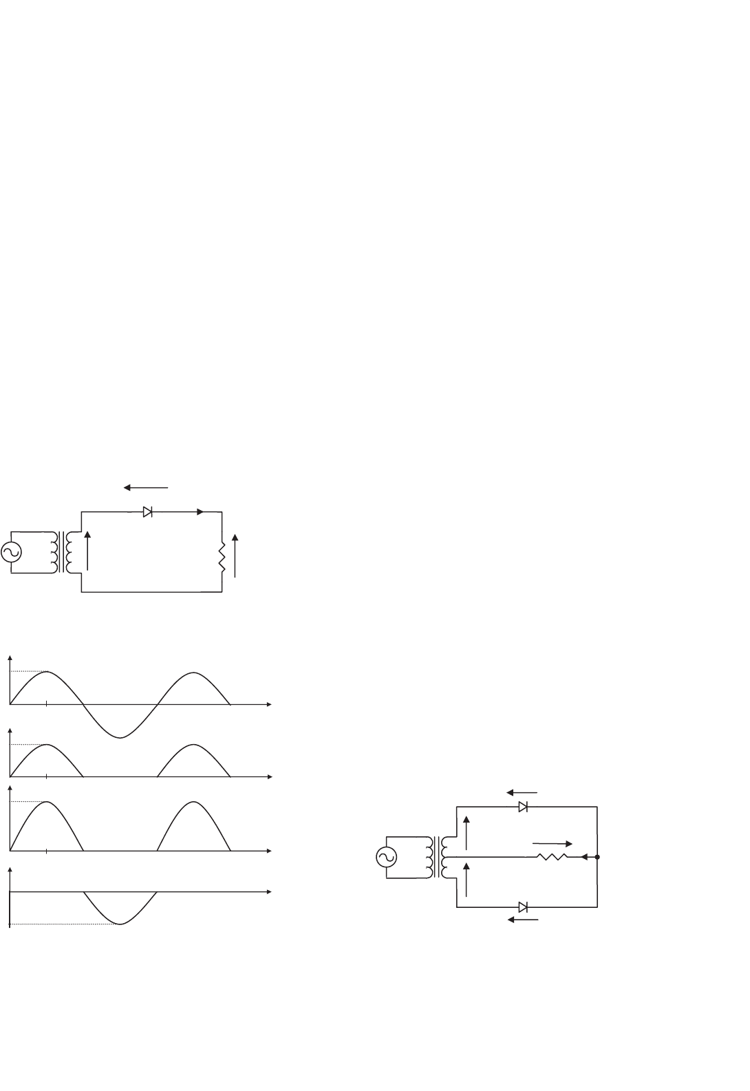
10.2.2 Single-phase Full-wave Rectifiers
There are two types of single-phase full-wave rectifier, namely,
full-wave rectifiers with center-tapped transformer and bridge
rectifiers. A full-wave rectifier with a center-tapped trans-
former is shown in Fig. 10.3. It is clear that each diode, together
with the associated half of the transformer, acts as a half-wave
rectifier. The outputs of the two half-wave rectifiers are com-
bined to produce full-wave rectification in the load. As far as
the transformer is concerned, the dc currents of the two half-
wave rectifiers are equal and opposite, such that there is no
dc current for creating a transformer core saturation problem.
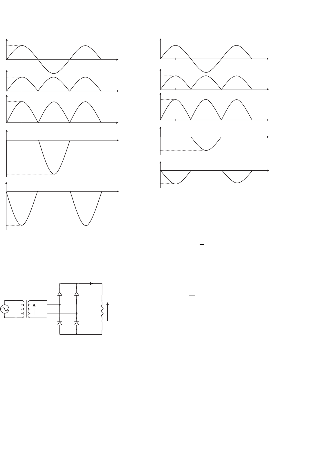
The voltage and current waveforms of the full-wave rectifier
are shown in Fig. 10.4. By observing diode voltage waveforms
v
D1
and v
D2
in Fig. 10.4, it is clear that the PIV of the diodes
is equal to 2V
m
during their blocking state. Hence the V
RRM
rating of the diodes must be chosen to be higher than 2V
m
to avoid reverse breakdown. (Note that, compared with the
half-wave rectifier shown in Fig. 10.1, the full-wave rectifier
has twice the dc output voltage, as shown in Section 10.2.4.)
During its conducting state, each diode has a forward current
which is equal to the load current, therefore the I
FRM
rating of
these diodes must be chosen to be higher than the peak load
current, V
m
= R, in practice.
Employing four diodes instead of two, a bridge rectifier as
shown in Fig. 10.5 can provide full-wave rectification without
using a center-tapped transformer. During the positive half-
cycle of the transformer secondary voltage, the current flows to
the load through diodes D
1
and D
2
. During the negative half-
cycle, D
3
and D
4
conduct. The voltage and current waveforms
of the bridge rectifier are shown in Fig. 10.6 As with the full-
wave rectifier with center-tapped transformer, the I
FRM
rating
of the employed diodes must be chosen to be higher than the
peak load current, V
m
= R. However, the PIV of the diodes is
reduced from 2V
m
to V
m
during their blocking state.
–
+
v
s
i
L
v
L
D
2
D
1
v
s
R
v
D1
v
D2
v
s
= V
m
sin wt
FIGURE 10.3 Full-wave rectifier with center-tapped transformer.
10 Diode Rectifiers 147
3p
3p
3p
3p
3pp/2
p/2
p/2
v
L
v
s
i
L
V
m
V
m
wt
wt
wt
wt
wt
2p
2p
2p
2p
2p
v
D2
v
D1
V
m
= R
–2V
–2V
D
1
conducts D
1
conductsD
2
conducts
p
p
p
p
p
FIGURE 10.4 Voltage and current waveforms of the full-wave rectifier
with center-tapped transformer.
v
s
v
L
i
L
R
D
1
D
2
D
3
D
4
v
s
= V
m
sin wt
+
−
FIGURE 10.5 Bridge rectifier.
10.2.3 Performance Parameters
In this subsection, the performance of the rectifiers mentioned
above will be evaluated in terms of the following parameters.
p/2
wt
wt
wt
wt
wt
2p 3p
v
D3
, v
D4
v
D1
, v
D2
–V
m
V
m
–V
m
D
1
,D
2
conduct
D
1
,D
2
conduct
D
3
,D
4
conduct
p
2p 3pp
2p 3pp
p/2 2 p 3 pp
p/2 2 p 3 pp
v
L
i
L
v
s
V
m
V
m
=R
FIGURE 10.6 Voltage and current waveforms of the bridge rectifier.
10.2.3.1 Voltage Relationships
The average value of the load voltage v
L
is V
dc
and it is
defined as
V
dc
=
1
T
T
0
v
L
(t) dt (10.1)
In the case of a half-wave rectifier, Fig. 10.2 indicates that
load voltage v
L
(t) = 0 for the negative half-cycle. Note that the
angular frequency of the source ω = 2π = T , and Eq. (10.1)
can be re-written as
V
dc
=
1
2π
π
0
V
m
sin ωtd(ωt) (10.2)
Therefore,
Half-wave V
dc
=
V
m
π
= 0.318V
m
(10.3)
In the case of a full-wave rectifier, Figs. 10.4 and 10.6 indi-
cate that v
L
(t) = V
m
|sin ωt |for both the positive and negative
half-cycles. Hence Eq. (10.1) can be re-written as
V
dc
=
1
π
π
0
V
m
sin ωtd(ωt) (10.4)
Therefore,
Full-wave V
dc
=
2V
m
π
= 0.636V
m
(10.5)

148 Y. S. Lee and M. H. L. Chow
The root-mean-square (rms) value of load voltage v
L
is V
L
,
which is defined as
V
L
=
1
T
T
0
v
2
L
(t)dt
1/2
(10.6)
In the case of a half-wave rectifier, v
L
(t) = 0 for the negative
half-cycle, therefore Eq. (10.6) can be re-written as
V
L
=
1
2π
π
0
(V
m
sin ωt )
2
d(ωt) (10.7)
or
Half-wave V
L
=
V
m
2
= 0.5V
m
(10.8)
In the case of a full-wave rectifier, v
L
(t) = V
m
|sin ωt | for
both the positive and negative half-cycles. Hence Eq. (10.6)
can be re-written as
V
L
=
1
π
π
0
(V
m
sin ωt )
2
d(ωt) (10.9)
or
Full-wave V
L
=
V
m
√
2
= 0.707V
m
(10.10)
The result of Eq. (10.10) is as expected because the rms value
of a full-wave rectified voltage should be equal to that of the
original ac voltage.
10.2.3.2 Current Relationships
The average value of load current i
L
is I
dc
and because load R
is purely resistive it can be found as
I
dc
=
V
dc
R
(10.11)
The rms value of load current i
L
is I
L
and it can be found as
I
L
=
V
L
R
(10.12)
In the case of a half-wave rectifier, from Eq. (10.3)
Half-wave I
dc
=
0.318V
m
R
(10.13)
and from Eq. (10.8)
Half-wave I
L
=
0.5V
m
R
(10.14)
In the case of a full-wave rectifier, from Eq. (10.5)
Full-wave I
dc
=
0.636V
m
R
(10.15)
and from Eq. (10.10)
Full-wave I
L
=
0.707V
m
R
(10.16)
10.2.3.3 Rectification Ratio
The rectification ratio, which is a figure of merit for comparing
the effectiveness of rectification, is defined as
σ =
P
dc
P
L
=
V
dc
T
dc
V
L
I
L
(10.17)
In the case of a half-wave diode rectifier, the rectification
ratio can be determined by substituting Eqs. (10.3), (10.13),
(10.8), and (10.14) into Eq. (10.17).
Half-wave σ =
(
0.318V
m
)
2
(
0.5V
m
)
2
= 40.5% (10.18)
In the case of a full-wave rectifier, the rectification ratio
is obtained by substituting Eqs. (10.5), (10.15), (10.10), and
(10.16) into Eq. (10.17).
Full-wave σ =
(
0.636V
m
)
2
(
0.707V
m
)
2
= 81% (10.19)
10.2.3.4 Form Factor
The form factor (FF) is defined as the ratio of the root-mean-
square value (heating component) of a voltage or current to
its average value,
FF =
V
L
V
dc
or
I
L
I
dc
(10.20)
In the case of a half-wave rectifier, the FF can be found by
substituting Eqs. (10.8) and (10.3) into Eq. (10.20).
Half-wave FF =
0.5V
m
0.318V
m
= 1.57 (10.21)
In the case of a full-wave rectifier, the FF can be found by
substituting Eqs. (10.16) and (10.15) into Eq. (10.20).
Full-wave FF =
0.707V
m
0.636V
m
= 1.11 (10.22)

10 Diode Rectifiers 149
10.2.3.5 Ripple Factor
The ripple factor (RF), which is a measure of the ripple
content, is defined as
RF =
V
ac
V
dc
(10.23)
where V
ac
is the effective (rms) value of the ac component of
load voltage v
L
.
V
ac
=
V
2
L
−V
2
dc
(10.24)
Substituting Eq. (10.24) into Eq. (10.23), the RF can be
expressed as
RF =
V
L
V
dc
2
−1 =
FF
2
−1 (10.25)
In the case of a half-wave rectifier,
Half-wave RF =
1.57
2
−1 = 1.21 (10.26)
In the case of a full-wave rectifier,
Full-wave RF =
1.11
2
−1 = 0.482 (10.27)
10.2.3.6 Transformer Utilization Factor
The transformer utilization factor (TUF), which is a measure
of the merit of a rectifier circuit, is defined as the ratio of the
dc output power to the transformer volt–ampere (VA) rating
required by the secondary winding,
TUF =
P
dc
V
s
I
s
=
V
dc
I
dc
V
s
I
s
(10.28)
where V
s
and I
s
are the rms voltage and rms current ratings
of the secondary transformer.
V
s
=
V
m
√
2
= 0.707V
m
(10.29)
The rms value of the transformer secondary current I
s
is the
same as that of the load current I
L
. For a half-wave rectifier, I
s
can be found from Eq. (10.14).
Half-wave I
s
=
0.5V
m
R
(10.30)
For a full-wave rectifier, I
s
is found from Eq. (10.16).
Full-wave I
s
=
0.707V
m
R
(10.31)
Therefore, the TUF of a half-wave rectifier can be obtained
by substituting Eqs. (10.3), (10.13), (10.29), and (10.30) into
Eq. (10.28).
Half-wave TUF =
0.318
2
0.707 ×0.5
= 0.286 (10.32)
The poor TUF of a half-wave rectifier signifies that the trans-
former employed must have a 3.496 (1/0.286) VA rating in
order to deliver 1 W dc output power to the load. In addition,
the transformer secondary winding has to carry a dc current
that may cause magnetic core saturation. As a result, half-wave
rectifiers are used only when the current requirement is small.
In the case of a full-wave rectifier with center-tapped trans-
former, the circuit can be treated as two half-wave rectifiers
operating together. Therefore, the transformer secondary VA
rating, V
s
I
s
, is double that of a half-wave rectifier, but the out-
put dc power is increased by a factor of four due to higher
the rectification ratio as indicated by Eqs. (10.5) and (10.15).
Therefore, the TUF of a full-wave rectifier with center-tapped
transformer can be found from Eq. (10.32)
Full-wave TUF =
4 ×0.318
2
2 ×0.707 ×0.5
= 0.572 (10.33)
In the case of a bridge rectifier, it has the highest TUF
in single-phase rectifier circuits because the currents flowing
in both the primary and secondary windings are continuous
sinewaves. By substituting Eqs. (10.5), (10.15), (10.29), and
(10.31) into Eq. (10.28), the TUF of a bridge rectifier can be
found.
Bridge TUF =
0.636
2
(
0.707
)
2
= 0.81 (10.34)
The transformer primary VA rating of a full-wave rectifier
is equal to that of a bridge rectifier since the current flowing
in the primary winding is also a continuous sinewave.
10.2.3.7 Harmonics
Full-wave rectifier circuits with resistive load do not produce
harmonic currents in their transformers. In half-wave recti-
fiers, harmonic currents are generated. The amplitudes of the
harmonic currents of a half-wave rectifier with resistive load,
relative to the fundamental, are given in Table 10.1. The extra
loss caused by the harmonics in the resistive loaded rectifier
circuits is often neglected because it is not high compared with
other losses. However, with non-linear loads, harmonics can
cause appreciable loss and other problems such as poor power
factor and interference.

150 Y. S. Lee and M. H. L. Chow
TABLE 10.1 Harmonic percentages of a half-wave rectifier with
resistive load
Harmonic 2nd 3rd 4th 5th 6th 7th 8th
% 21.2 0 4.2 0 1.8 0 1.01
10.2.4 Design Considerations
In a practical design, the goal is to achieve a given dc output
voltage. Therefore, it is more convenient to put all the design
parameters in terms of V
dc
. For example, the rating and turns
ratio of the transformer in a rectifier circuit can be easily deter-
mined if the rms input voltage to the rectifier is in terms of
the required output voltage V
dc
.
Denote the rms value of the input voltage to the rectifier
as V
s
, which is equal to 0.707V
m
. Based on this relation and
Eq. (10.3), the rms input voltage to a half-wave rectifier is
found as
Half-wave V
s
= 2.22V
dc
(10.35)
Similarly, from Eqs. (10.5) and (10.29), the rms input
voltage per secondary winding of a full-wave rectifier is
found as
Full-wave V
s
= 1.11V
dc
(10.36)
Another important design parameter is the V
RRM
rating of
the diodes employed.
In the case of a half-wave rectifier, from Eq. (10.3),
Half-wave V
RRM
= V
m
=
V
dc
0.318
= 3.14V
dc
(10.37)
TABLE 10.2 Important design parameters of basic single-phase rectifier circuits with resistive load
Half-wave
rectifier
Full-wave rectifier
with center-tapped
transformer
Full-wave bridge
rectifier
Peak repetitive reverse voltage V
RRM
3.14V
dc
3.14V
dc
1.57V
dc
RMS input voltage per transformer leg V
s
2.22V
dc
1.11V
dc
1.11V
dc
Diode average current I
F(AV)
1.00I
dc
0.50I
dc
0.50I
dc
Peak repetitive forward current I
FRM
3.14I
F(AV)
1.57I
F(AV)
1.57I
F(AV)
Diode rms current I
F(RMS)
1.57I
dc
0.785I
dc
0.785I
dc
Form factor of diode current I
F(RMS)
/I
F(AV)
1.57 1.57 1.57
Rectification ratio 0.405 0.81 0.81
Form factor 1.57 1.11 1.11
Ripple factor 1.21 0.482 0.482
Transformer rating primary VA 2.69P
dc
1.23P
dc
1.23P
dc
Transformer rating secondary VA 3.49P
dc
1.75P
dc
1.23P
dc
Output ripple frequency f
r
1f
i
2f
i
2f
i
In the case of a full-wave rectifier with center-tapped
transformer, from Eq. (10.5),
Full-wave V
RRM
= 2V
m
=
2V
dc
0.636
= 3.14V
dc
(10.38)
In the case of a bridge rectifier, also from Eq. (10.5),
Bridge V
RRM
= V
m
=
V
dc
0.636
= 1.57V
dc
(10.39)
It is important to evaluate the I
FRM
rating of the employed
diodes in rectifier circuits.
In the case of a half-wave rectifier, from Eq. (10.13),
Half-wave I
FRM
=
V
m
R
=
I
dc
0.318
= 3.41I
dc
(10.40)
In the case of full-wave rectifiers, from Eq. (10.15),
Full-wave I
FRM
=
V
m
R
=
I
dc
0.636
= 1.57I
dc
(10.41)
The important design parameters of basic single-phase rec-
tifier circuits with resistive loads are summarized in Table 10.2.
10.3 Three-phase Diode Rectifiers
It has been shown in Section 10.2 that single-phase diode recti-
fiers require a rather high transformer VA rating for a given dc
output power. Therefore, these rectifiers are suitable only for
low to medium power applications. For power output higher
than 15 kW, three-phase or poly-phase diode rectifiers should
be employed. There are two types of three-phase diode rectifier
that convert a three-phase ac supply into a dc voltage, namely,
star rectifiers and bridge rectifiers. In the following subsections,

10 Diode Rectifiers 151
the operations of these rectifiers are examined and their perfor-
mances are analyzed and compared in tabulated form. For the
sake of simplicity, the diodes and the transformers are consid-
ered to be ideal, i.e. the diodes have zero forward voltage drop
and reverse current, and the transformers possess no resistance
and no leakage inductance. Furthermore, it is assumed that the
load is purely resistive, such that the load voltage and the load
current have similar waveforms. In Section 10.5 Filtering Sys-
tems in Rectifier Circuits, the effects of inductive load and
capacitive load on a diode rectifier are considered in detail.
10.3.1 Three-phase Star Rectifiers
10.3.1.1 Basic Three-phase Star Rectifier Circuit
A basic three-phase star rectifier circuit is shown in Fig. 10.7.
This circuit can be considered as three single-phase half-
wave rectifiers combined together. Therefore it is sometimes
referred to as a three-phase half-wave rectifier. The diode in a
particular phase conducts during the period when the voltage
on that phase is higher than that on the other two phases. The
voltage waveforms of each phase and the load are shown in
Fig. 10.8. It is clear that, unlike the single-phase rectifier cir-
cuit, the conduction angle of each diode is 2π/3, instead of π.
This circuit finds uses where the required dc output voltage is
relatively low and the required output current is too large for
a practical single-phase system.
2p
p
p
p
3p
2p
3p
2p 3p
p/6
i
D
v
D
V
m
/R
–1.73V
m
wt
wt
wt
wt
v
BN
V
m
v
RN
v
YN
5p/6
V
m
v
L
FIGURE 10.8 Waveforms of voltage and current of the three-phase star rectifier shown in Fig. 10.7.
v
L
i
D
v
D
N
B
R
Y
D
R
v
RN
v
YN
v
BN
FIGURE 10.7 Three-phase star rectifier.
Taking phase R as an example, diode D conducts from π/6
to 5π/6. Therefore, using Eq. (10.1) the average value of the
output can be found as
V
dc
=
3
2π
5π/6
π/6
V
m
sin θdθ (10.42)
or
V
dc
= V
m
3
π
√
3
2
= 0.827V
m
(10.43)
Similarly, using Eq. (10.6), the rms value of the output
voltage can be found as
V
L
=
3
2π
5π/6
π/6
(
V
m
sin θ
)
2
dθ (10.44)

152 Y. S. Lee and M. H. L. Chow
TABLE 10.3 Important design parameters of the three-phase rectifier circuits with the resistive load
Three-phase
star rectifier
Three-phase
double-star rectifier
with inter-phase
transformer
Three-phase
bridge rectifier
Peak repetitive reverse voltage V
RRM
2.092V
dc
1.06V
dc
1.05V
dc
RMS input voltage per transformer leg V
s
0.855V
dc
0.855V
dc
0.428V
dc
Diode average current I
F(AV)
0.333I
dc
0.167I
dc
0.333I
dc
Peak repetitive forward current I
FRM
3.63I
F(AV)
3.15I
F(AV)
3.14I
F(AV)
Diode rms current I
F(RMS)
0.587I
dc
0.293I
dc
0.579I
dc
Form factor of diode current I
F(RMS)
/I
F(AV)
1.76 1.76 1.74
Rectification ratio 0.968 0.998 0.998
Form factor 1.0165 1.0009 1.0009
Ripple factor 0.182 0.042 0.042
Transformer rating primary VA 1.23P
dc
1.06P
dc
1.05P
dc
Transformer rating secondary VA 1.51P
dc
1.49P
dc
1.05P
dc
Output ripple frequency f
r
3f
i
6f
i
6f
i
or
V
L
= V
m
3
2π
π
3
+
√
3
4
= 0.84V
m
(10.45)
In addition, the rms current in each transformer secondary
winding can also be found as
I
s
= I
m
1
2π
π
3
+
√
3
4
= 0.485I
m
(10.46)
where I
m
= V
m
/R.
Based on the relationships stated in Eqs. (10.43), (10.45),
and (10.46), all the important design parameters of the three-
phase star rectifier can be evaluated, as listed in Table 10.3,
which is given at the end of Subsection 10.3.2. Note that, as
with a single-phase half-wave rectifier, the three-phase star
rectifier shown in Fig. 10.7 has direct currents in the sec-
ondary windings that can cause a transformer core saturation
problem. In addition, the currents in the primary do not sum
R
R’
B
B’
Y
Y’
FIGURE 10.9 Three-phase inter-star rectifier.
to zero. Therefore it is preferable not to have star-connected
primary windings.
10.3.1.2 Three-phase Inter-star Rectifier Circuit
The transformer core saturation problem in the three-phase
star rectifier can be avoided by a special arrangement in its sec-
ondary windings, known as zig-zag connection. The modified
circuit is called the three-phase inter-star or zig-zag rectifier
circuit, as shown in Fig. 10.9. Each secondary phase voltage
is obtained from two equal-voltage secondary windings (with
a phase displacement of π/3) connected in series so that the
dc magnetizing forces due to the two secondary windings on
any limb are equal and opposite. At the expense of extra sec-
ondary windings (increasing the transformer secondary rating
factor from 1.51 to 1.74 VA/W), this circuit connection elimi-
nates the effects of core saturation and reduces the transformer
primary rating factor to the minimum of 1.05 VA/W. Apart
from transformer ratings, all the design parameters of this
circuit are the same as those of a three-phase star rectifier
(therefore not separately listed in Table 10.3). Furthermore, a
star-connected primary winding with no neutral connection
10 Diode Rectifiers 153
is equally permissible because the sum of all primary phase
currents is zero at all times.
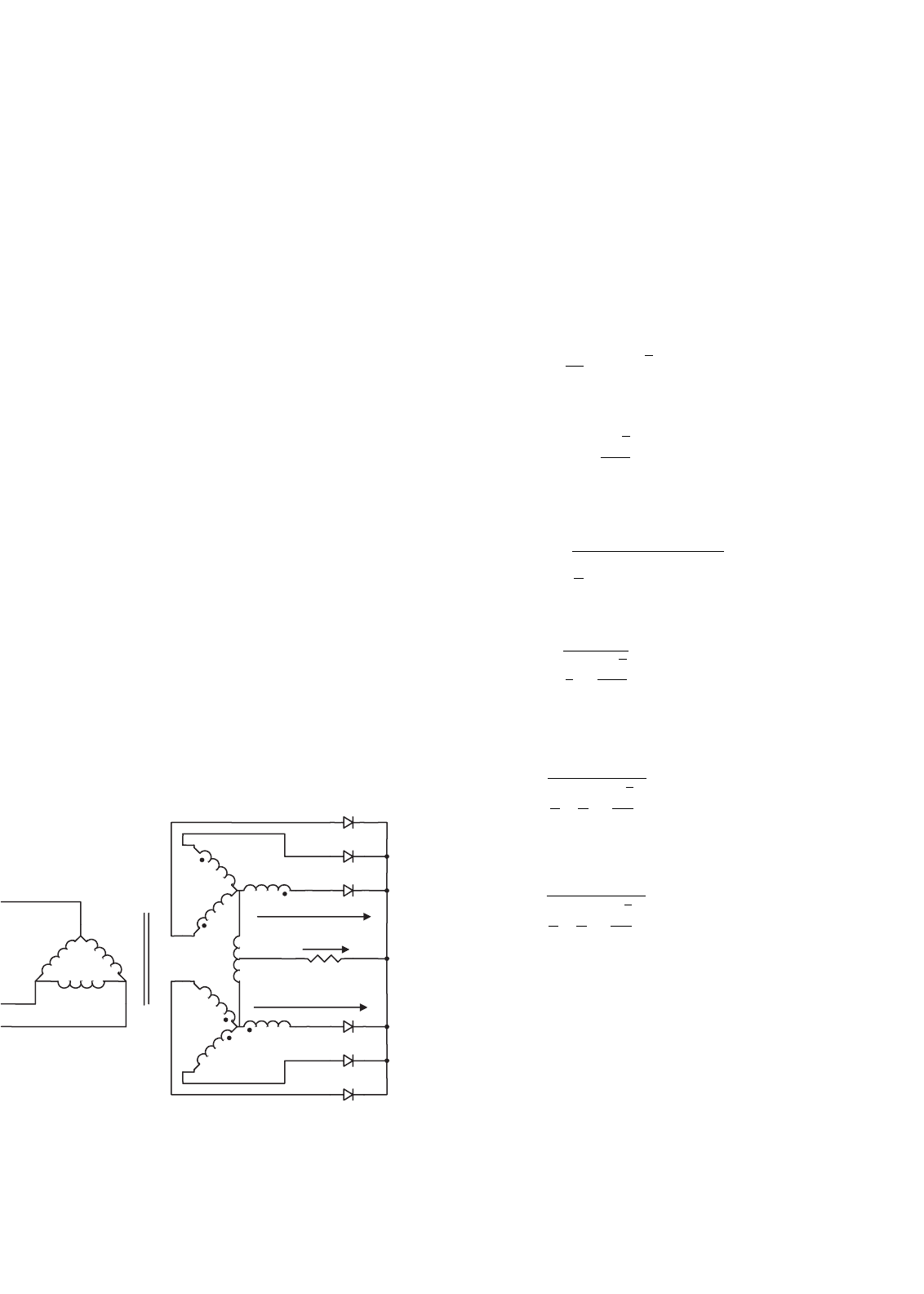
10.3.1.3 Three-phase Double-star Rectifier with
Inter-phase Transformer
This circuit consists essentially of two three-phase star rectifiers
with their neutral points interconnected through an inter-
phase transformer or reactor (Fig. 10.10). The polarities of the
corresponding secondary windings in the two interconnected
systems are reversed with respect to each other, so that the rec-
tifier output voltage of one three-phase unit is at a minimum
when the rectifier output voltage of the other unit is at a max-
imum as shown in Fig. 10.11. The function of the inter-phase
transformer is to cause the output voltage v
L
to be the aver-
age of the rectified voltages v1 and v2 as shown in Fig. 10.11.
In addition, the ripple frequency of the output voltage is now
six times that of the mains and therefore the component size
of the filter (if there is any) becomes smaller. In a balanced
circuit, the output currents of two three-phase units flowing
in opposite directions in the inter-phase transformer wind-
ing will produce no dc magnetization current. Similarly, the
dc magnetization currents in the secondary windings of two
three-phase units cancel each other out.
By virtue of the symmetry of the secondary circuits, the
three primary currents add up to zero at all times. Therefore,
a star primary winding with no neutral connection would be
equally permissible.
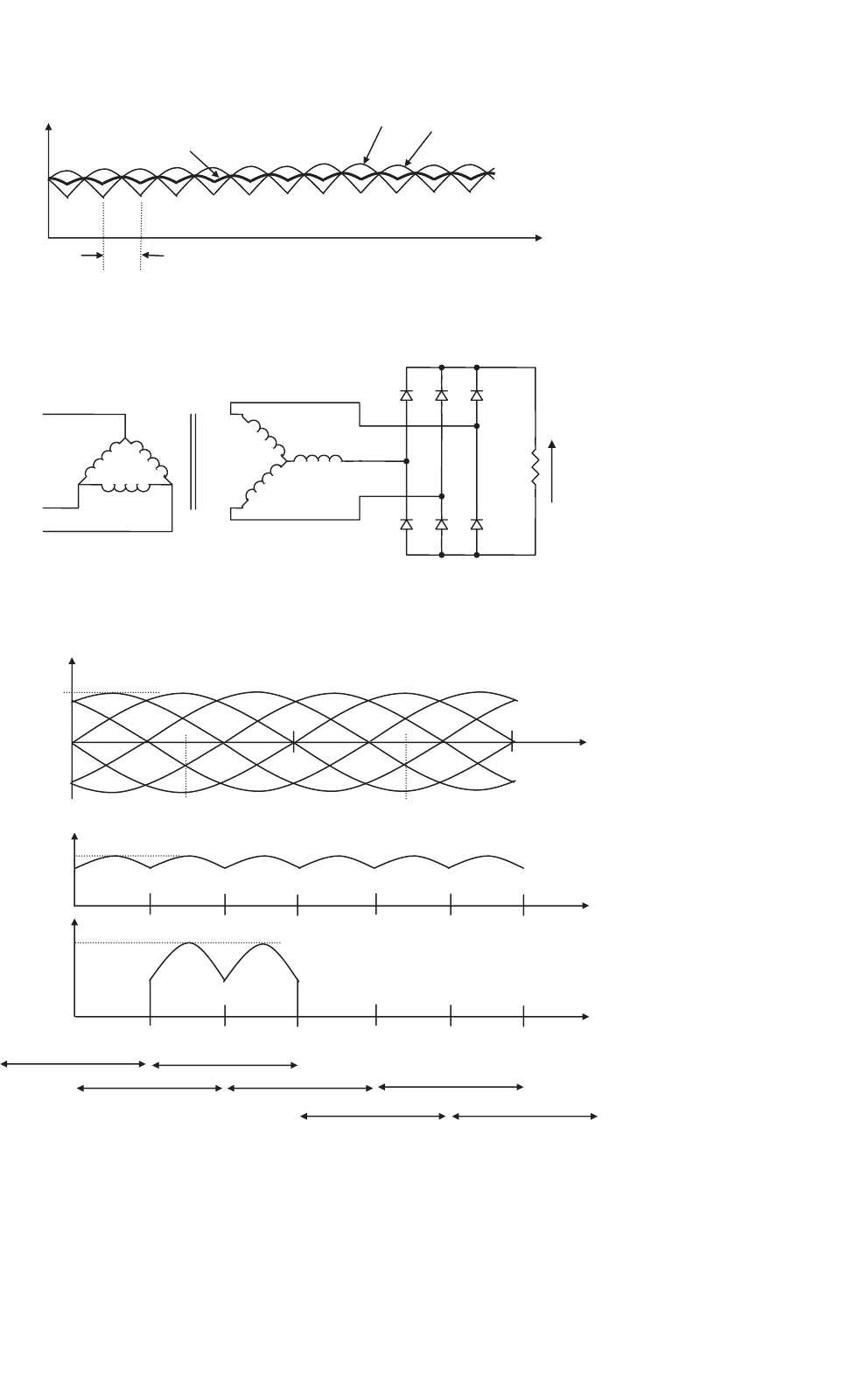
10.3.2 Three-phase Bridge Rectifiers
Three-phase bridge rectifiers are commonly used for high
power applications because they have the highest possible
transformer utilization factor for a three-phase system. The
circuit of a three-phase bridge rectifier is shown in Fig. 10.12.
v
L
v1
v2
FIGURE 10.10 Three-phase double-star rectifier with inter-phase trans-
former.
The diodes are numbered in the order of conduction sequences
and the conduction angle of each diode is 2π/3.
The conduction sequence for diodes is 12, 23, 34, 45,
56, and 61. The voltage and the current waveforms of the
three-phase bridge rectifier are shown in Fig. 10.13. The line
voltage is 1.73 times the phase voltage of a three-phase star-
connected source. It is permissible to use any combination
of star- or delta-connected primary and secondary windings
because the currents associated with the secondary windings
are symmetrical.
Using Eq. (10.1) the average value of the output can be
found as
V
dc
=
6
2π
2π/3
π/3
√
3V
m
sin θdθ (10.47)
or
V
dc
= V
m
3
√
3
π
= 1.654V
m
(10.48)
Similarly, using Eq. (10.6), the rms value of the output
voltage can be found as
V
L
=
9
π
2π/3
π/3
(
V
m
sin θ
)
2
dθ (10.49)
or
V
L
= V
m
3
2
+
9
√
3
4π
= 1.655V
m
(10.50)
In addition, the rms current in each transformer secondary
winding can also be found as
I
s
= I
m
2
π
π
6
+
√
3
4
= 0.78I
m
(10.51)
and the rms current through a diode is
I
D
= I
m
1
π
π
6
+
√
3
4
= 0.552I
m
(10.52)
where I
m
= 1.73V
m
/R.
Based on Eqs. (10.48), (10.50), (10.51), and (10.52), all the
important design parameters of the three-phase star rectifier
can be evaluated, as listed in Table 10.3. The dc output voltage
is slightly lower than the peak line voltage or 2.34 times the
rms phase voltage. The V
RRM
rating of the employed diodes
is 1.05 times the dc output voltage, and the I
FRM
rating of
the employed diodes is 0.579 times the dc output current.
Therefore, this three-phase bridge rectifier is very efficient and
154 Y. S. Lee and M. H. L. Chow
v2
v1
v
L
wt
p/3
FIGURE 10.11 Voltage waveforms of the three-phase double-star rectifier.
D
1
D
2
D
3
D
4
D
5
D
6
v
L
R
B
Y
FIGURE 10.12 Three-phase bridge rectifier.
v
BR
v
YB
v
BY
v
L
i
Di
v
RB
v
RY
v
YR
2p
1.73V
m
1.73V
m
1.73V
m
/ R
2p5p/3
3p/2
4p/32p/3p/3
p/2
wt
wt
wt
D
6
conducts D
4
conducts
D
3
conducts
D
1
conducts
D
2
conducts
D
5
conducts
D
5
conducts
2p5p/34p/32p/3p/3
p
p
p
FIGURE 10.13 Voltage and current waveforms of the three-phase bridge rectifier.