Morling K. Geometric and Engineering Drawing
Подождите немного. Документ загружается.


Geometric and Engineering Drawing304
Example 2
Electrical Coil Winding Machine
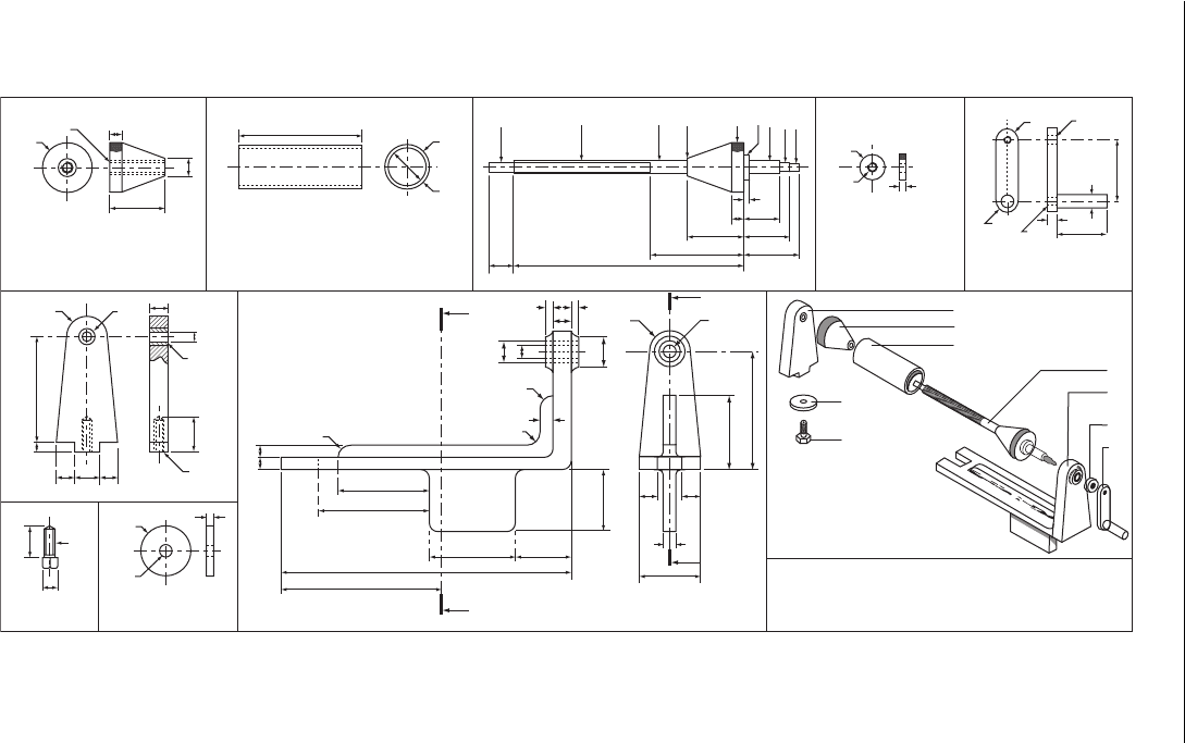
A pictorial view and details of each component part of a coil winding machine are shown
( Fig. 18.38 ). A clip which fastens the wire to the coil former has not been included.
Draw , full size, either in first or third angle projection the following views of the
unit completely assembled.
(i) A sectional FE taken on the cutting plane YY. Shown in body detail Part E.
(ii) A sectional EE taken on the cutting plane XX. Shown in body detail Part E.
(iii) A plan projected from view (i).
Hidden detail is not required in any view.
Use your own judgement to determine the size of any dimension not given.
A dimension shown as M10, for example, should be understood as
M means metric thread.
10 means diameter of the shaft or hole in mm.
Make sure that the views are correctly positioned and in correct projection before
drawing in any detail.
Credit will be given for good draughtsmanship and layout as well as for correct
answers.
(i) Print in the title – COIL WINDING MACHINE – size of letters to be 7 mm high.
(ii) Print in the scale and the system of projection used.
(iii) Put in the following dimensions:
(a) the overall height of the assembled machine;
(b) the length between the outside ends of the coil former locking nuts;
(c) the length between the inner faces of the end bearing brackets.
Associated Lancashire Schools Examining Board
Engineering Drawing 305
10
100
45
R17
5
Bronze
bush
Bronze
bush
R10
R10
R10
R17
Y
X
55
15
10
75
90
130
235
X
70 45
50
15 15
60
95
10
Y
50
1010
85
15
25
20 15
M8
14AF
M8
8
30
15
M10
Coil former locking nut
End bearing
Washer
Bolt
Par t B
Par t A
Part J Part H
Body
Par t E
Spindle locking nut
Par t F
Spindle handle
Par t G
A
B
C
D
E
F
G
H
J
Component parts aligned
ready for assembly
Coil winder
Electrical coil winding machine
First angle projection
All dimensions in millimetres
Coil former
Par t C
Par t D
φ40
φ36
φ8
φ10
φ15
φ20
φ40
φ20
φ10
φ10
M8
M6
M10
20 185
75
45
30
M8
5
R9 M6
M8
R9
7
40
50
38
45
5
10
Spindle
φ30
φ15
φ14
φ16
φ25
φ10
φ40
φ9
φ8
Figure 18.38 Specimen examination question.
Geometric and Engineering Drawing306
Scale 1:1 Coil winding machine
X
X
Y
Section Y–Y
Y
165 mm
190 mm
148 mm
Section X–X
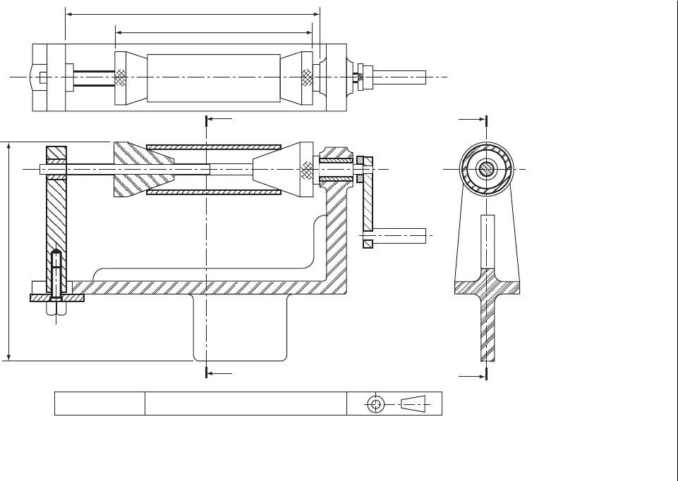
Figure 18.39 Scaled solution to Fig. 18.38 which shows a sectioned assembly of an electrical coil winding machine.

Engineering Drawing 307
Example 3
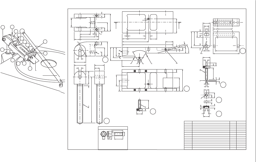
Figure 18.40A is a pictorial view of a jig used to hold woodworker ’ s plane irons and
chisels at a set angle to the flat wheel surface of a grinding machine ( Figure 18.41 ).
The jig is shown in position for grinding a plane iron.
For chisels, the jig is swivelled so that the master arm (6) is the other way up, and
the blade clamping shoe (9) is swung round so that the chisel may be clamped.
The grinding angle may be altered by screwing the column (1) up or down.
The blade is moved to and fro across the face of the wheel by means of the oper-
ating lever which engages on the spigot on the clamping screw (12). For the purpose
of this examination, the lever has been omitted.
Figure 18.40B shows detail drawings, in third angle projection , of the compo-
nents of the plane iron grinding angle jig.
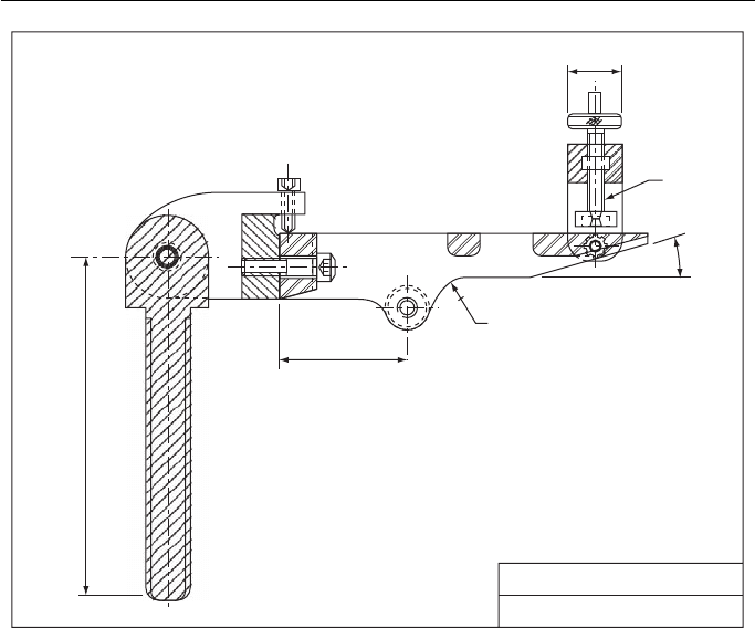
Draw , full size, a sectional elevation on the section plane X – X, with all the com-
ponents assembled and the clamping screw (12) on the section plane and to the right
of the view. The column (1) should be perpendicular, the master arm unit (4 and 6)
horizontal and the blade clamping screw (12) perpendicular. In this view do not sec-
tion the slot nut (13) and pad (14).
Correctly dimension: a horizontal measurement,
a vertical measurement,
an angular measurement (angle),
a radius,
a diameter, and
a screw thread.
Correctly position a suitable title block and state the following information.
Title : PLANE IRON GRINDING ANGLE JIG
Scale : Full size
Southern Universities ’ Joint Board
Geometric and Engineering Drawing308
1
8
2
3
4
5
6
12
13
7
9
14
Blade
(A)
(B)
1
Lever
11
10
14
13
12
11
10
9
8
7
6
5
4
3
2
1
Part No.
1
1
1
2
2
1
2
1
1
2
1
2
1
1
No. off
Brass
B.M.S
B.M.S
B.M.S
Steel
C.iron
B.M.S
Steel
C.iron
Steel
C.iron
B.M.S
Steel
B.M.S
Material
Pad
Slot nut
Clamping screw
Washers, MG light gauge
Hex. socket cap screws, MG x 16
Blade clamping shoe
Retaining screws (chisels)
Hex. socket cap screw, MG x 35
Master arm
Hex. socket set screws, MG x 20 dog point
Master arm bracket
Hex. locking nuts, MG
Hex. socket shoulder screw x10 MG thread
Column
Par t
34
35
52
2 holes MG.
20
R50
φ10
φ10
φ40
φ6
φ25
φ6
φ6
φ6
φ14
φ20
φ4
φ40
65
8
XX
2
66
1212
10
50
30
M8
2025
34
17
5
160
Hex. socket cap screws.
Thread A H J K F
All detail part nos at bottom right of part
All fillets and RADII 5 mm
All dimensions in millimetres
Third angle projection
T
Max Max Nom Min Max Nom
10 6 5 33 0.4 18
13 8 6 43 0.6 22
Size D
M6
M8
M20
15
60
50
25
15
8
R20
10
5
17.5
10
15
6
6
4
M8
7
40
M8
Choclip
groove
15 50
75
90
MG
2
18 62
90
10
5
25
25
55
48
18
5
6
676
10
20
15°
4
175
45
38
37.5
MG
30
7
φ20
10
75
35
10
12
35
30
10
15°
60°
R10
R10 R10
M6 x10 deep
60
MG
30
8
6
9
12
13
14
4
Figure 18.40 Specimen examination question.
Engineering Drawing 309
φ 25 mm
M8 mm
Plane iron angle gripping JIG
Scale: Full size
15°
R10 mm
60 mm
160 mm
Figure 18.41 Scaled solution to Fig. 18.40 .
Geometric and Engineering Drawing310
Exercise 18
(All questions originally set in imperial units.)
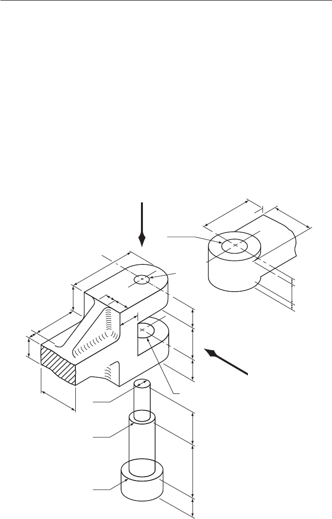
1. Figure 1 shows a detail from a stationary engine. Draw this detail with the parts assembled.
You may use either first or third angle projection.
Draw, twice full size:
(a) A sectional FE in the direction of arrow B . The section should be parallel to the sides
of the rod and pass through the centre of the hinge bolt.
(b) A plan in the direction of arrow A and projected from the elevation. Show all hid-
den detail in this view: (i) the smallest diameter spigot on the bolt should be shown
threaded M10 for 15 mm and the bolt should be fastened by an M10 nut; (ii) six main
dimensions should be added to the views; (iii) print the title ‘ Safety valve operating
link detail ’ in the bottom right-hand corner of your sheet in 6 mm letters; (iv) in the
bottom left-hand corner of the sheet print the type of projection you have used.
East Anglian Examinations Board
40
25
9
40
50
25
7
9
15
12.5
φ12
φ10
φ12
φ10
All dimensions in mm
All fillets 2 radius
Safety valve
operating linkage
A
B
φ12
φ16
12
3
12
3
1812223010
12.5
Figure 1
Engineering Drawing 311
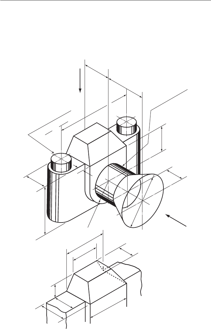
2. Figure 2 shows in pictorial projection the proportions of a miniature camera with a lens
hood attached. The lower drawing shows in detail the dimensions of the viewfinder, the
rear face of which is vertical.
Using either first or third angle orthographic projection, draw, full size, the following
views: (a) an elevation in the direction of arrow A ; (b) a plan in the direction of arrow B .
Metropolitan Regional Examinations Board
32
25
50
32
50
88
High
18
9
φ18
φ68
25
32
48
R 25
18
15
56
28
B
Barrel φ38
Winding knobs
Dimensions in mm
7
A
22
Figure 2
Geometric and Engineering Drawing312
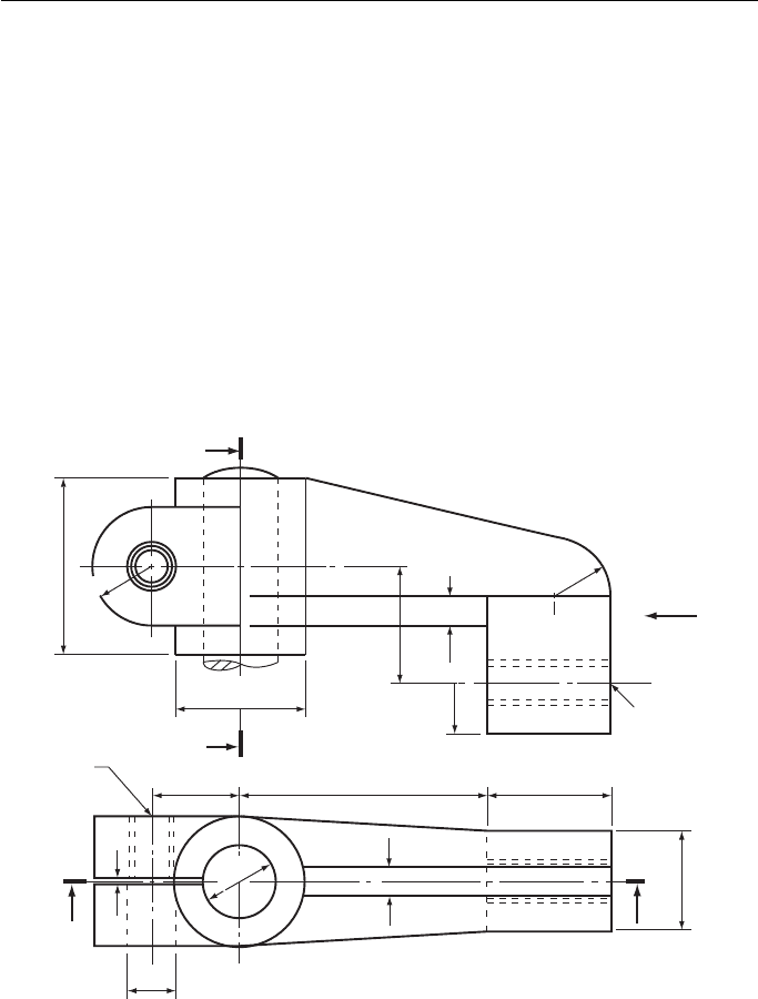
3. Figure 3 shows two views of a gear-change lever bracket from a lathe. When in use, the
bracket is clamped to the 32 mm diameter axle by a bolt passing through the 19 mm diam-
eter hole and screwing into the M18 threaded hole. The bolt is hexagon-headed, 62 mm
long, with the thread running for 44 mm. With a portion of the axle in position and the
bolt screwed tight, draw the following views of the bracket, full size, in either first or third
angle projection: (a) the given plan; (b) a sectional front view on the section line A – A;
(c) a sectional end view on the section line B – B; (d) an end view in the direction of arrow C .
Show hidden detail in view (a) only.
Insert, in a title block in the bottom right-hand corner of your paper, the title GEAR-
CHANGE LEVER BRACKET, the scale and projection used. Any dimensions not shown
are left to your discretion.
Note : The bracket is a casting and the fillets and radiused corners have been left out to sim-
plify the drawing. Do not insert fillets and radiused corners in your drawing.
Middlesex Regional Examining Board
φ56
φ19
φ32
B
38 106
First angle projection
12
44
M 18
A
A
3
53
R 25
M 18
C
All dimensions in mm
B
50
R 22
R 25
12
76
Figure 3
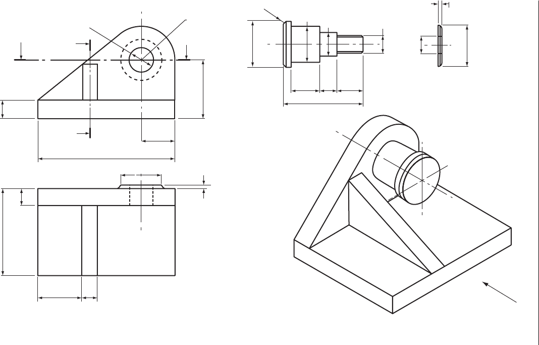
4. A sketch and views of a lever bracket are given in Fig. 4 . The pin fits into the hole in the
bracket and is held in position by means of an M18 hexagon nut.
Draw, full size, the following views of the assembled bracket, including the nut: (a) a FE
looking in the direction of arrow X ; (b) a sectional end view on AA looking in the direction
of the arrows; (c) a sectional plan on BB looking in the direction of the arrows.
Engineering Drawing 313
94
3
50
All dimensions in mm
Lever bracket
150
A
38
32
18 28
84
Pin
X
Washer
A
B
B
M 18
R 38
3
φ25
φ50
φ38
φ25
φ44
φ19
15
18
18
62
φ38
Figure 4
