Morling K. Geometric and Engineering Drawing
Подождите немного. Документ загружается.

Geometric and Engineering Drawing254
Simple Cam Design
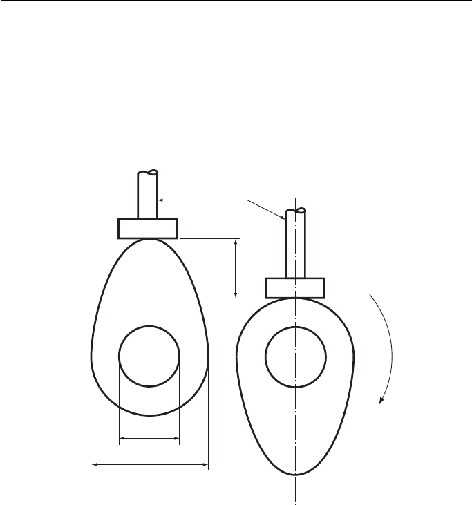
Cams are used in machines to provide a controlled up and down movement. This
movement is transmitted by means of a follower . A cam with a follower is shown in
Fig. 17.13 in the maximum ‘ up ’ and ‘ down ’ positions. The difference between these
two positions gives the lift of the cam. The shape of the cam, its profile , determines
how the follower moves through its lift and fall .
R
o
t
a
t
i
o
n
Follower
Lift/fall
Shaft diameter
Minimum cam diameter
Figure 17.13 Simple cam and follower.
Some More Problems Solved by Drawing 255
Uniform velocity
Lift/fallLift/fallLift/fall
1 Rotation of cam
Simple harmonic motion
Uniform acceleration and retardation
Figure 17.14 Types of lift and fall.
A cam is designed to make a pan of a machine move in a particular way. For
example, cams are used to open and close the valves that control the petrol mix-
ture going into and the exhaust gases coming out of an internal combustion engine.
Obviously the valves must open at the right time and at the right speed and it is the
cam that determines this. This control on the valve is exercised by the profile of the
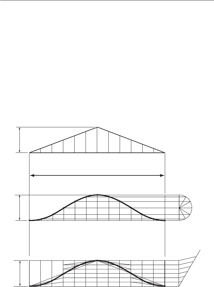
cam, determining how the follower lifts and falls. Three examples of types of lift and
fall are shown in Fig. 17.14 .
The top diagram shows uniform velocity. This is a graph of a point that is moving
at the same velocity ‘ upward ’ to halfway and then at the same velocity ‘ downward ’
to its starting point.
The centre diagram shows simple harmonic motion. This is the motion of a pen-
dulum, starting with zero velocity, accelerating to a maximum and then decelerating
to zero again (at the top of the curve) and then repeating the process back to the start-
ing point. The curve is a sine curve and is plotted as shown.
Geometric and Engineering Drawing256
Shaft diameter
6
7
8
9
10
11
12
1
2
3
4
5
Minimum cam diameter
Specification
Shaft diameter 15 mm
Minimum diameter 30 mm
Lift 15 mm
Performance 90° uniform velocity to maximum lift
180° dwell
90° uniform velocity to maximum fall
Rotation Anti-clockwise
Linear
velocity
90°
Linear
velocity
90°
Dwell
180°
Rotation
Performance curve
1 Rotation − 360°
10 11 12987645321
12
Lift/fall
Figure 17.15 Cam design.
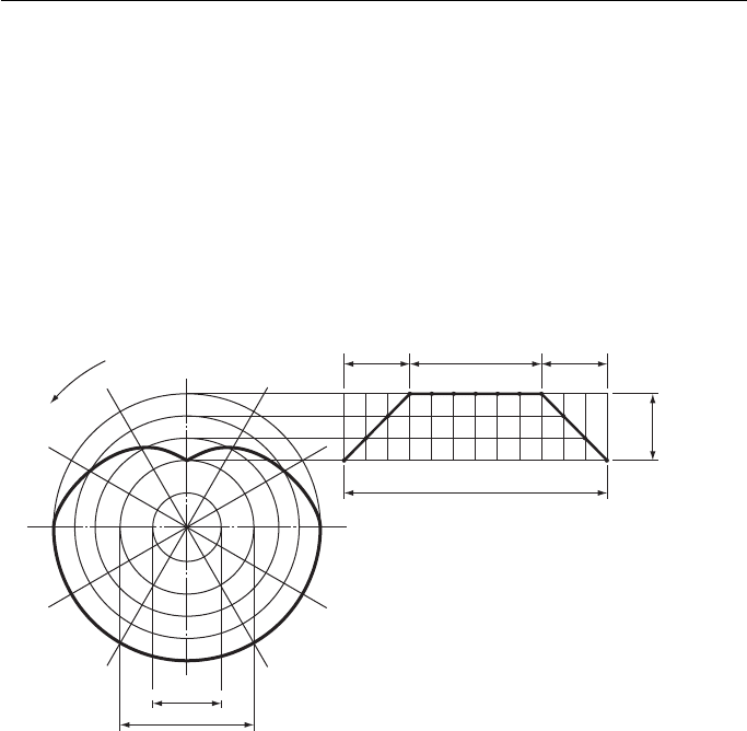
The performance curve is started by drawing a base line of 12 equal parts, the total
representing one rotation of the cam. The lift/fall is then marked out, and the perfor-
mance curve drawn. The base line of the performance curve is then projected across
and, with the centre line of the cam, forms the top of the circle representing the mini-
mum cam diameter. Once the centre of the cam has been found centre lines can be
drawn at 30 ° intervals. The cam profile is plotted on these lines. Twelve points on the
performance curve are then projected across to the centre line of the cam and then
swung round with compasses to the intersecting points on the lines drawn at 30 ° inter-
vals. If the cam is rotating clockwise the points 1 to 12 are marked out clockwise; if the
rotation is anti-clockwise, as in this case, the points are marked out anti-clockwise.
The lower diagram shows uniform acceleration and retardation. In this case the
acceleration is uniform to a point halfway up the lift and then retarding uniformly to
the maximum lift. The process is then repeated in reverse back to the starting point.
The curve is plotted as shown.
If a cam has to be designed it is drawn around a specification. This must state the
dimensions, the lift/fall and the performance. The performance states how the fol-
lower is to behave throughout one rotation of the cam. The designer must first draw
the performance curve to the given specification. An example is shown in Fig. 17.15 .
Dwell is a period when the follower is neither lifting nor falling.
Some More Problems Solved by Drawing 257
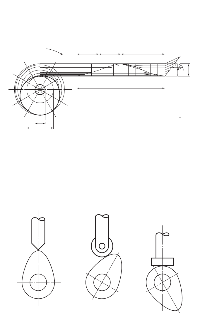
Figure 17.16 shows another example of a cam design.
This is a more complicated profile than the previous example but the method used
to construct the profile is the same. This cam rotates in a clockwise direction.
1 Rotation − 360°
Linear velocity
90°
Simple harmonic
motion
90°
Uniform retardation
180°
Lift
121110987654321
1
1
2
3
4
5
1
2
3
4
5
10
11
9
8
7
6
10
11
9
8
7
6
2
3
4
5
6
Shaft diameter
Minimum cam diameter
7
8
9
10
11
12
Rotation
12
Performance curve
Specification
Shaft diameter 10 mm
Minimum diameter 25mm
Lift 13 mm
Performance 90° uniform velocity to maximum lift
90° simple harmonic motion to maximum lift at rotation
180° uniform retardation to maximum fall
Rotation Clockwise
1
2
1
2
Figure 17.16 Cam design.
Knife Roller Flat
Figure 17.17 Three types of cam followers.
Finally , three different types of follower are shown in Fig. 17.17 . The left-hand
example is a knife follower. It can be used with a cam that has a part of its profile con-
vex but it wears quickly. The centre example is a roller follower; this type of follower
obviously reduces friction between the follower and the cam, something of a problem
with the other types shown. The flat follower is an all-purpose type which is widely
used. It wears more slowly than a knife follower.
Geometric and Engineering Drawing258
Exercise 17
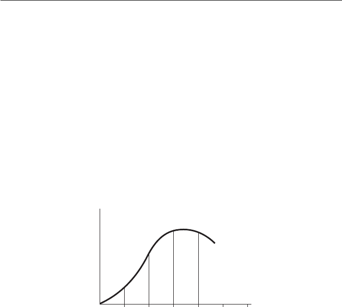
1. The velocity of a vehicle moving in a straight line from start to rest was recorded at
intervals of 1 minute and these readings are shown in the table. Part of the velocity/time
diagram is given in Fig. 1 .
Draw the complete diagram with a horizontal scale of 10 mm to 1 minute and vertical scale
of 10 mm to 1 m/s. Using the mid-ordinate rule, determine the average velocity of the vehi-
cle and hence the total distance travelled in the 12 minutes.
Time, t
(min)
0 1 2 3 4 5 6 7 8 9 10 11 12
Velocity,
v (m/s)
0 1.4 5.4 9.2 8.6 7.9 9.0 10.2 11.5 12.6 9.4 5.2 0
Oxford Local Examinations
0 123
Time t (min)
Velocity (m/s)
456
Figure 1
Some More Problems Solved by Drawing 259
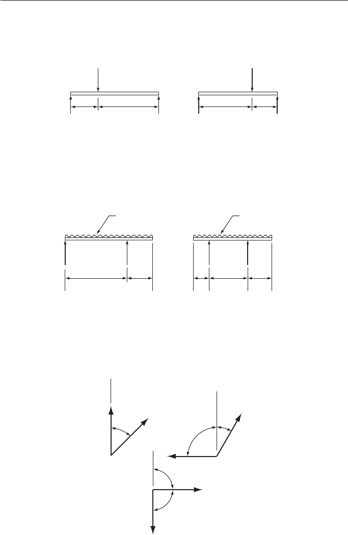
3. Figure 3 shows four simply loaded beams. Find the size of the reactions marked X.
3
6
X
X
6
3
5
X
6 m
3 units/metre
X
2
11
X
Figure 3
0
Y
X
10 20 30
Figure 2
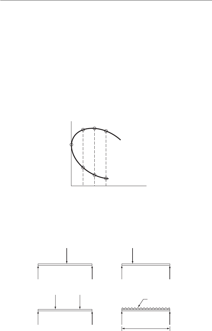
2. Figure 2 shows part of an indicator diagram which was made during an engine test. Draw the
complete diagram, full size, using the information given in the table and then by means of the
mid-ordinate rule determine the area of the diagram. Also, given that the area of the diagram
can be given by the product of its length and average height, determine the average height and
the average pressure if the ordinates represent the pressure to a scale of 1 mm to 60 kN/m
2
.
OX(mm) 0 10 20 30 40 50
O Y
max
(mm) 54 79 82 78 66 54
O Y
min
(mm) 54 21 14 12 12 12
OX (mm) 60 70 80 90 100
O Y
max
(mm) 45 39 33 29 21
O Y
min
(mm) 12 12 12 13 21
Oxford Local Examinations
Geometric and Engineering Drawing260
613
3
42
x4
58
x
Figure 4
3 units/metre
53
2 units/metre
523
Figure 5
4. Figure 4 shows two simply loaded beams with their reactions. Find the dimensions marked
x for the loading to be in equilibrium (the couples to be equal).
5. Figure 5 shows two beams loaded with evenly distributed loads. The positions of the reac-
tions are shown. Find the size of the reactions.
6. Figure 6 shows three examples of two forces acting at a point. Find the size of the resultant
force for each example and measure the angular direction of the resultant force from the
datum shown.
2
3
7
4
5
8
45°
90°
90°
90°
30°
Datum
Datum
Datum
Figure 6
Some More Problems Solved by Drawing 261
3
4
2
7
3
5
6
330°
180°
300°
270°
135°
45°
60°
Datum
Datum
Figure 7
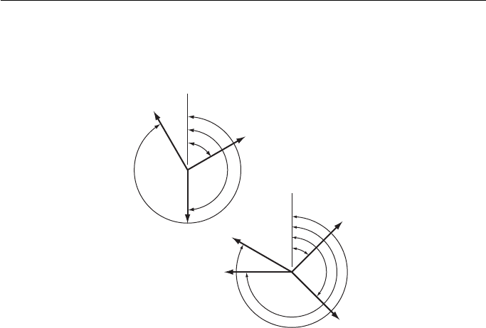
7. Figure 7 shows two examples of forces acting at a point. Find the size of the resultant force
for both examples and measure and state the angular direction of the resultant force from
the datum shown. From the same datum state the angular direction of the equilibrant force
for both examples.
8. Plot the cam profile which meets the following specification:
Shaft diameter 15 mm
Minimum diameter 25 mm
Lift 12 mm
Performance 90 ° uniform velocity to maximum lift
90 ° dwell
180 ° uniform retardation to maximum
fall
Rotation Clockwise
Your cam profile must be drawn, twice full size
9. Plot the cam profile which meets the following specifications:
Shaft diameter 12.5 mm
Minimum diameter 30 mm
Lift 12.5 mm
Performance 60 ° dwell
90 ° simple harmonic motion to half lift
30 ° dwell
60 ° uniform acceleration to maximum lift
120 ° uniform velocity to maximum fall
Rotation Anti-clockwise
Your cam profile is to be drawn, twice full size.
This page intentionally left blank

Part 2
Engineering Drawing
18. Engineering Drawing 265
19. Postscript – Planning a Design 337
