Morling K. Geometric and Engineering Drawing
Подождите немного. Документ загружается.

Geometric and Engineering Drawing274
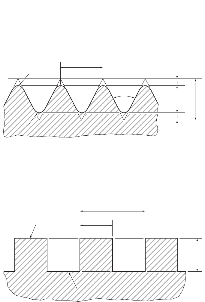
The British Standard Whitworth thread has now been superseded by the ISO
thread. However, the ISO has adopted the Whitworth profile for pipe threads. It is
called the British Standard Pipe Thread, Figure 18.11 .
There are some special threads that have been designed to fulfil functions for
which a vee thread would be inadequate. Some are shown.
Crest
Root
Root
Pitch
55°
D
D = 0.96 P
D
6
D
6
Figure 18.11 British standard pipe thread. (British Standard Whitworth thread profile)
Crest
Root
Root
Pitch/2
Pitch/2
Pitch
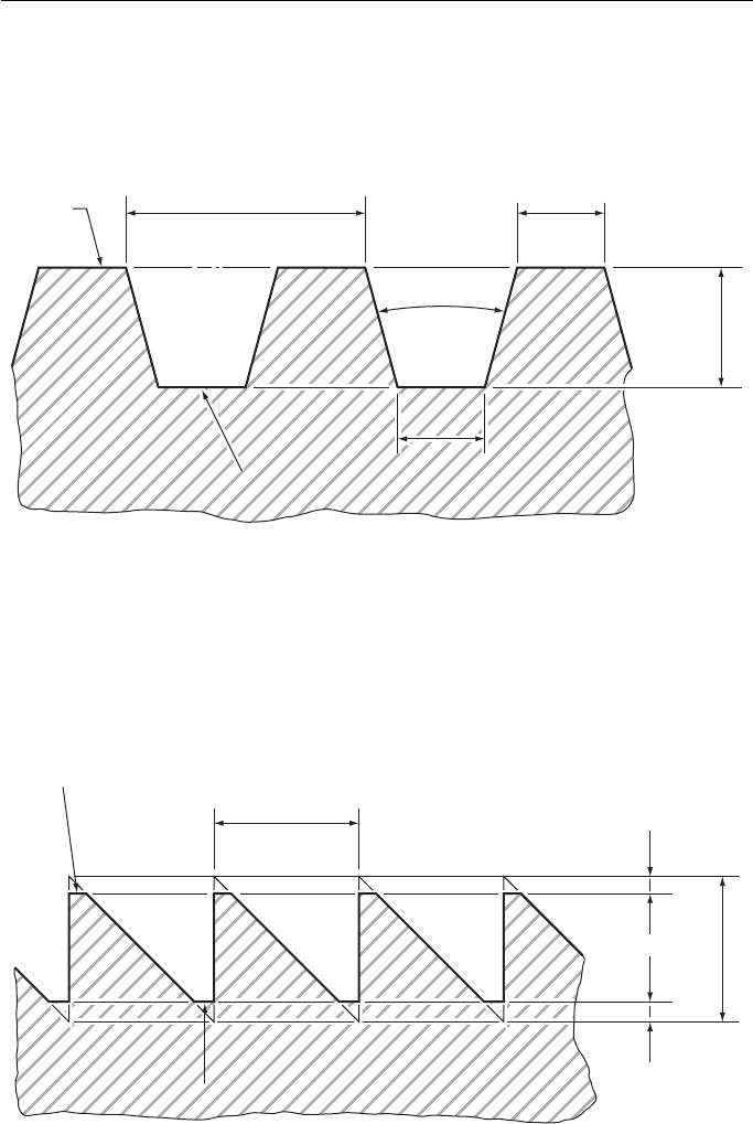
Figure 18.12 Square thread profile.
The square thread, Fig. 18.12 , is now rarely used because it has been superseded
by the acme thread. Its main application is for transmitting power since there is less
friction than with a vee thread.
Engineering Drawing 275
The acme thread, Fig. 18.13 , is extensively used for transmitting power. The
thread form is easier to cut than the square thread because of its taper and, for the
same reason, it is used on the lead screw of lathes where the half-nut engages easily
on the tapered teeth.
Crest
Pitch
Root
Root
0.3707 P
0.3707 P
0.3707 P
0.5 P + 0.01"
29°
Figure 18.13 Acme thread profile.
Crest
Root
Root
Pitch
D = P
D
8
D
8
Figure 18.14 Buttress thread profile.
The Buttress thread, Fig. 18.14 , combines the vee thread and the square thread
without retaining any of their disadvantages. It is a strong thread and has less friction
than a vee thread. Its main application is on the engineer ’ s vice although it is some-
times seen transmitting power on machines.
Geometric and Engineering Drawing276
Drawing Screw Threads
Drawing a screw thread properly is a long and tedious business. A square thread has
been drawn in full see Fig. 15.12 and you can see that this type of construction would
take much too long a time on a drawing that has several threads on it and would be
physically impossible on a small thread.
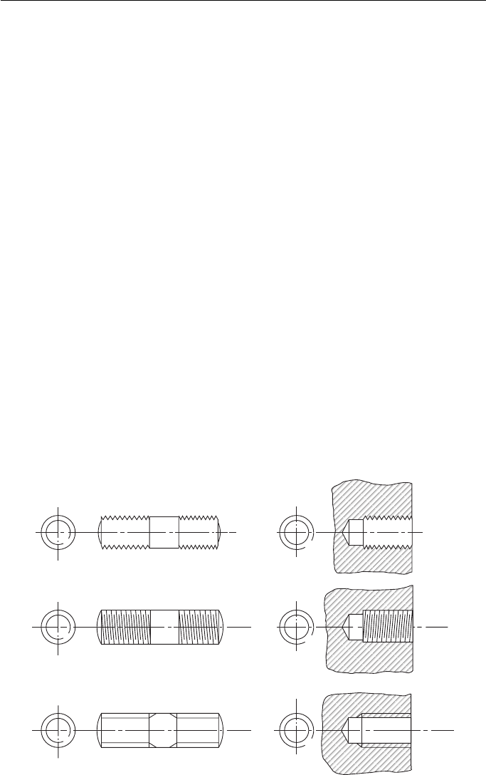
There are conventions for drawing threads which make life very much easier.
Three conventional methods of representing screw threads are shown in Fig. 18.15 .
The top two methods are not used on engineering drawings any more. One of these
illustrates the shape of the thread and the other has lines representing the thread crest
and root. The bottom drawing shows how to draw a screw thread on an engineering
drawing; the parallel lines represent the thread crest and root.
The only convention which shows whether the thread is right- or left-handed is the
second one. This is not much of an advantage because the thread has to be dimen-
sioned and it is a simple matter to state whether a thread is right- or left-handed.
Left-hand threads are rarely met with and, unless specifically stated, a thread is
assumed to be right-handed.
Figure 18.15 shows the convention for both external and internal threads. It should
be explained that, on the drawings for internal threads, the thread does not reach to the
bottom of the hole. When an internal thread is cut, the material is first drilled a little
deeper than is actually required. The diameter of the hole is the same as the root diam-
eter of the thread and is called the tapping diameter. The screw thread is then cut with
a tap, but the tap cannot reach right to the bottom of the hole and some of the tapping
hole is left. The cutting angle of the drill, for normal purposes, is 118 ° – almost 120 ° .
Thus, a 60 ° set square is used to draw the interior end of an internal screw thread.
External
(Used only in technical illustrations)
(Used only in technical illustrations)
(Used on engineering drawings)
Internal
Figure 18.15 Conventional representation of screw threads.

Engineering Drawing 277
Nuts and Bolts
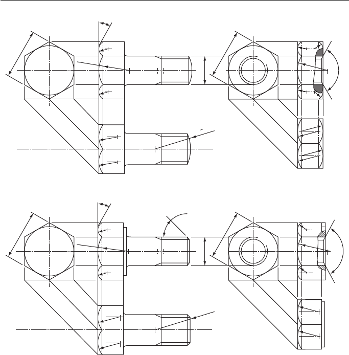
The most widespread application of the screw thread is the nut and bolt showing full
details to whenever a nut or bolt is drawn; it is essential that the first view drawn
is the one which shows the regular hexagon. If the across-flats (A/F) dimension is
given, draw a circle with that diameter. If it is not, look in Appendix A under the
appropriate thread size. Construct a regular hexagon round the circle with a 60 ° set
square. Project the corners of the hexagon onto the side view of the nut and bolt and
mark off the thickness of the nut or bolt head (see Appendix A).
Nuts and bolts are chamfered and, when viewed from the side, this chamfer is seen
as radii on the sides of the nut or bolt. If you ensure that the first view projected from
the hexagon is the one which shows three faces of the nut (the other view shows only
two faces), you can draw a radius equal to D , the diameter of the thread, on the centre
flat. The intersection of this radius and the corners of the neighbouring flats determines
the size of the two smaller radii. These must start at this intersection, finish at the same
height on the next corner and touch the top of the nut or bolt at the centre of the flat.
This may be done by trial and error with compasses, or with radius curves. Remember
that the centre of the radius lies midway between the sides. This view is completed by
drawing the 30 ° chamfer which produced the radii.
The third view of the nut or bolt is drawn in a similar fashion. The width and
heights are projected from the two existing views and the radii are found in the same
way as shown on the other view. However, BS 308 recommends a simplified method
of drawing nuts and bolts and this is shown in Appendix C.
Two types of standard nuts and bolts are shown in Fig. 18.16 . Type A is standard.
Type B has a ‘ washer face ’ underneath the head of the bolt and on one face of the nut.
The threaded end of the bolt may be finished off with a spherical radius equal to
1
1
4
D or a 45 ° chamfer to just below the root of the thread. Both of these enable the
nut to engage easily and leave no sharp projections. The thread on the nut is also
chamfered to assist easy engagement.
The length of a bolt is determined simply by the use to which the bolt is to be put.
There is a very large selection of bolt lengths for all diameters. The bolt should not
protrude very far past the nut and so there is no need to thread all of the shank. The
amount of thread on a bolt is given in the table below.
Length of bolt Length of thread
Up to and including 125 mm
2 d 6 m m
Over 125 mm and up to and including 200 mm
2 d 1 2 m m
Over 200 m m
2 d 2 5 m m
d is the diameter of the bolt.
These lengths are the minimum thread lengths.
Bolts that are too short for minimum thread lengths are called screws .
An ISO metric nut or bolt is easily recognised by the letter ‘ M ’ or ISO M on the
head or flats.
Geometric and Engineering Drawing278
Designation of ISO Screw Threads
The coarse series ISO thread is only one of 12 different threads in the ISO series. This
thread, like the fine thread series, has a pitch which varies with the diameter of the bolt.
The remaining 10 thread series have constant pitches, whatever the diameter of the thread.
All the series except the coarse thread series are used in special circumstances.
The vast majority of threads used come from the coarse thread series.
The method used on drawings for stating an ISO thread is quite simple. Instead
of stating the thread form and series you need only use the letter ‘ M ’ . The diameter
of the thread is stated immediately after ‘ M ’ . Thus M12 is ISO thread form, 12 mm
diameter thread and M20 is ISO thread form, 20 mm diameter thread. In many coun-
tries the designation shown above is used to denote a coarse thread series . If a thread
30° Chamfer
45° Chamfer
to thread
root
30° Chamfer
Nut and bolt type A
Nut and bolt Type B
See Appendix A for nut, bolt and washer proportions
D
D
D
D
R = D
R = D
A/F
A/F
A/F
A/F
120°
120°
1
D
1
4
Figure 18.16

Engineering Drawing 279
is used from a constant pitch series, it is added after, so that M14 1.5 is a 14 mm
diameter ISO thread with a constant pitch of 1.5 mm.
However , in this country the British Standard requires that the pitch be included
in the coarse thread series. Thus, a thread with the designation M30 3.5 is a coarse
series ISO thread with a pitch of 3.5 mm.
A thread with the designation M16 2 is a coarse series ISO thread with a pitch
of 2 mm.
There are further designations concerned with the tolerances, or accuracy of man-
ufacture, but these are beyond the scope of this book.
Types of Bolts and Screws
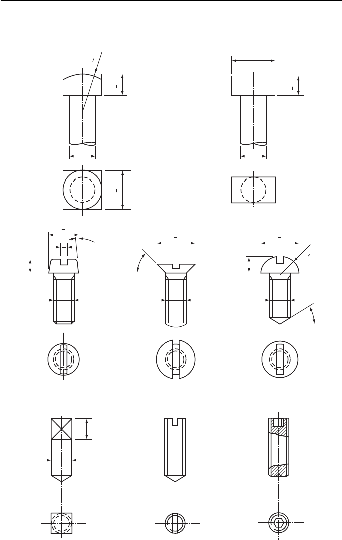
There are many types of heads for bolts and screws apart from the standard hexago-
nal head. Some are shown in Fig. 18.17 .
Figure 18.17 shows only a few types of bolt and screw heads that are in use. There are
wedged-shaped heads, tommy heads, conical heads, hook bolts and eye bolts. There are
small, medium and large headed square screws, 60 ° , 120 ° and 140 ° countersunk screw
heads with straight slots, cross slots and hexagonal slots. There are instrument screws
and oval cheese-headed screws to name only a few. The dimensions for all these
screws can be obtained from any good engineering handbook. However, BS 308 also
recommends a simplified method of drawing screws. This is shown in Appendix C.
Dimensioning
When an engineering drawing is made, dimensioning is of vital importance. All the
dimensions necessary to make the articles drawn must be on the drawing and they
must be presented so that they can be easily read, easily found and not open to mis-
interpretation. A neat drawing can be spoilt by bad dimensioning.
In British drawing practice the decimal point is shown in the usual way, i.e. 15.26. In
Europe , however, the decimal point in metric units is a comma, i.e. 15,26 or 0,003.
Also , in the metric system a space is left between every three digits, i.e. 12 056.0
or 0.002 03. Note that values less than unity are prefixed by a nought. Engineering
drawings are usually dimensioned in millimetres, irrespective of the size of the
dimension, but the centimetre and metre are also sometimes used ( Fig. 18.18 ).
There are many rules about how to dimension a drawing properly, but it is unlikely
that two people will dimension the same drawing in exactly the same way. However,
remember when dimensioning that you must be particularly neat and concise, thor-
ough and consistent. The following rules must be adhered to when dimensioning:
1. Projection lines should be thin lines and should extend from about 1 mm from the outline
to 3 mm to 6 mm past the dimension line.
2. The dimension line should be a thin line and terminate with arrowheads at least 3 mm long
and these arrowheads must touch the projection lines.
3. The dimension may be inserted within a break in the dimension line or be placed on top of
the dimension line.
Geometric and Engineering Drawing280
First angle projection
Bolt heads
Cheese
Square Screwdriver slot grub screw
D
D
DD
DD
D
0.80
D
7
8
30°
45°
5°
Hexagon slotted
grub screw
(Allen screw)
Screw heads
countersunk
Round
Square T head for M/C tools
D
7
8
D
3
4
D1
4
3
D1
4
3
D1
4
3
D1
2
1
D1
2
1
D1
2
1
D
3
2
D
4
Figure 18.17 Bolt heads and screw heads.
Engineering Drawing 281
4. The dimensions should be placed so that they are read from the bottom of the paper or
from the right-hand side of the paper.
5. Dimension lines should be drawn outside the outline, whenever possible, and should be
kept well clear of the outline.
6. Overall dimensions should be placed outside the intermediate dimensions.
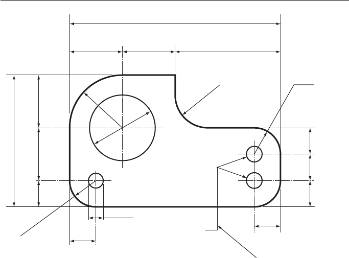
7. Centre lines must never be used as dimension lines. They may be used as projection lines
( Fig. 18.19 ).
8. Diameters may be dimensioned in one of two ways. Either dimension directly across the
circle ( not on a centre line), or project the diameter to outside the outline. ‘ Diameter ’ is
denoted by the symbol φ placed in front of the dimension.
9. When dimensioning a radius, you must, if possible, show the centre of the radius. The
actual dimension for the radius may be shown either side of the outline but should, of
course, be kept outside if possible. The word radius must be abbreviated to R and placed
in front of the dimension.
10. When a diameter or a radius is too small to be dimensioned by any of the above meth-
ods, a leader may be used. The leader line should be a thin line and should terminate on
the detail that it is pointing to with an arrowhead or, within an outline, with a dot. Long
leader lines should be avoided even if it means inserting another dimension. The leader
line should always meet another line at an acute angle.
11. Dimensions should not be repeated on a drawing. It is necessary to put a dimension on
only once, however many views are drawn. There is one exception to this rule. If, by
inserting one dimension, it saves adding up lots of small dimensions then this is allowed.
These types of dimensions are called ‘ auxiliary dimensions ’ and are shown to be so either
by underlining the dimensions or putting it in brackets.
12. Unless unavoidable, do not dimension hidden detail. It is usually possible to dimension
the same detail on another view.
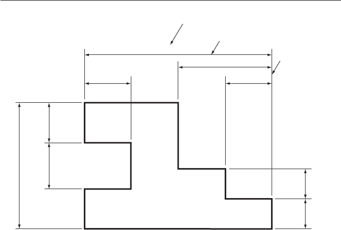
Dimension
75 mm
37.5 mm
18 mm18 mm
50 mm
18 mm
12.5 mm 12.5 mm
16 mm
Dimension line
Projection line
Figure 18.18 Illustrating rules 1 – 6.
Geometric and Engineering Drawing282
13. When dimensioning angles, draw the dimension lines with a compass; the point of the com-
pass should be on the point of the angle. The arrowheads may be drawn either side of the
dimension lines, and the dimension may be inserted between the dimension lines or outside
them. Whatever the angle, the dimension must be placed so that it can be read from either
the bottom of the paper or from the right-hand side.
14. If a lot of parallel dimensions are given, it avoids confusion if the dimensions are stag-
gered so that they are all easier to read.
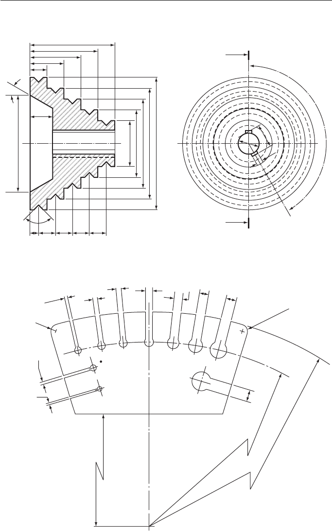
15. If a lot of dimensions are to be shown from one projection line (often referred to as a datum
line ), either of the methods shown in Fig. 18.20 may be used. Note that in both methods, the
actual dimension is close to the arrowhead and not at the centre of the dimension line.
16. If the majority of dimensions on a drawing are in one unit, it is not necessary to put on
the abbreviation for the units used, i.e. cm or mm. In this case, the following note must be
printed on your drawing.
UNLESS OTHERWISE STATED, DIMENSIONS ARE IN MILLIMETRES
17. If a very large radius is drawn, whose centre is off the drawing, the dimension line is
drawn with a single zig-zag in it.
18. Dimensioning small spaces raises its own problems and solutions. Some examples are
shown in Fig. 18.21 . There are one or two more rules that do not require illustrating.
19. If the drawing is to scale, the dimensions put on the drawing are the actual dimensions of
the component and not the size of the line on your drawing.
The above 19 rules do not cover all aspects of dimensioning (there is a new
set on toleranced dimensions alone) but they should cover all that is necessary.
Dimensioning properly is a matter of applying common sense to the rules because no
80 mm
20 mm 20 mm 40 mm
10 mm
20 mm20 mm
(50 mm)
10 mm
10 mm10 mm
10 mm
Leader line
φ 5 mm
φ 25 mm
2 Holes - φ 5 mm
R 12.5 mm
R 10 mm
R 10 mm
R 20 mm
Figure 18.19 Illustrating rules 7 – 11.
Engineering Drawing 283
X
X
50
40
30
20
10
30°
90°
515253545
12.5
φ 54
φ 25
φ 37.5
φ 50
φ 62.5
φ 75
Datum line
Third angle projection
Unless otherwise stated, all dimensions are in millimetres
150°
14
φ 12
4
Figure 18.20 Illustrating rules 12 – 16.
Dimensions in mm
2
R 2.5
R 2.5
R 135
R 145
2.5
3
3.5
R 100
Diameter hole A – 2
""
B – 2.5
""
C – 3
""
D – 3.5
""
E – 4
""
F – 5
""
G – 6
""
H – 7
""
J – 8
""
K – 9
4.5
5
4
1.5
1
A
B
C
D
EF
G
H
J
K
5.5
Figure 18.21 Illustrating rules 17 and 18.
