Morling K. Geometric and Engineering Drawing
Подождите немного. Документ загружается.


Geometric and Engineering Drawing294
Note that the title is given prominence over all the other information. Also note
that the system of projection is at the top of the paper. This is because it is really a
note on the drawing rather than an additional piece of information. The list of part
numbers would be used only if several parts were drawn on the same drawing and
would not, therefore, be shown on every drawing.
Assembly Drawings
There are not many engineering items that are completely functional by themselves.
There are some, a spanner or a rule for instance, but even a simple object like a wood
chisel has three components and a good pair of compasses may have 12 component
parts. Each part should be drawn and dimensioned separately and then a drawing is
made of all the component parts put together. This is called an ‘ assembly drawing ’ .
The student at school or college is often instructed to draw the assembled components
only and is shown the dimensioned details in no particular order. If the assembly is
particularly difficult, the parts are often shown in an exploded view and the assembly
presents no difficulty. The assembled parts may form an object which is easily recog-
nisable, but the real problem occurs when there seems to be no possible connection
between any of the component parts. In an examination, when loss of time must be
avoided at all costs, the order of assembly needs to be worked out quickly.
The only approach is to view the assembly somewhat like a jigsaw puzzle. The
parts must fit together and be held together, either because they interlock or there is
something holding them together.
Learn to look for similar details on separate components. If there is an internal
square thread on one component and an external thread of the same diameter on
another component, the odds are that one screws inside the other. If two different
components have two or more holes with the same pitch, it is likely that they are
joined at those two holes. A screw with an M10 thread must fit an M10 threaded
hole. A tapered component must fit another tapered component.
The important thing, particularly in examinations, is to start drawing. Never spend
too long trying to puzzle out an assembly. There is always an obvious component to
start drawing, and, while you are drawing that, the rest of the assembly will become
apparent as you become more familiar with the details.
Some Engineering Fastenings
We have already seen how to draw a standard nut and bolt. Some other types of bolts
and screws are shown in Fig. 18.17 (on page 280) with their principal dimensions.
There are, however, many other types of fastenings in everyday use in industry, and
some of them are shown later.
Engineering Drawing 295
The Stud and Set Bolt
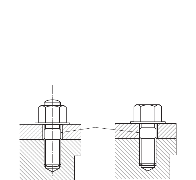
The stud and set bolt (sometimes called a tap bolt or cap screw) are used when it is
impossible or impractical to use a nut and bolt. Figure 18.27 shows both in their final
positions. They are both screwed into a tapped hole in the bottom piece of material.
The top piece of material is drilled slightly larger than the stud or screw and is held
in position by a nut and washer in the case of the stud, and by the head of the set bolt
and washer in the case of the set bolt.
The stud would be used when the two pieces of material were to be taken apart quite
frequently; the set bolt would be used if the fixing was expected to be more permanent.
Clearance
Set bolt (Longer thread than
standard bolt)
Stud (Threaded both ends)
Figure 18.27
Locking Devices
Constant vibration tends to loosen nuts and, if a nut is expected to be subjected to
vibration, a locking device is often employed. There are two basic groups of locking
devices: one group increases the friction between the nut and the bolt or stud; the
other group is more positive and is used when heavy vibration is anticipated or where
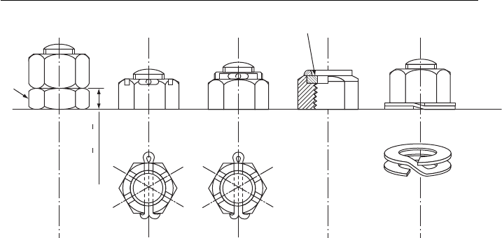
the loss of a nut would be catastrophic. Figure 18.28 shows five common locking
devices.
The locknut is very widely used. The smaller nut should be put on first and, when
the larger nut is tightened, the two nuts strain against each other. The smaller nut
pushes upwards. The reaction in the larger nut is to push downwards against the
smaller nut and, since it must move upwards to undo, it is locked in position.
The slotted nut and castle nut are used when the nut must not undo. The nut is
tightened and then a hole is drilled through the bolt through one of the slots. A split
Geometric and Engineering Drawing296
pin is inserted and the ends are bent over. A new split pin should be used each time
the nut is removed.
The self-locking nut is now very widely used. The nylon or fibre washer is com-
pressed against the bolt thread when the nut is tightened. This nut should only be
used once since the nylon or fibre is permanently distorted once used.
The spring washer pushes the nut up against the bolt thread, thus increasing the
frictional forces. It is the least effective of the locking devices shown and should only
be used where small vibrations are expected.
There are many other types of locking device and full descriptions can be found
in any good engineering handbook.
Rivets and Riveted Joints
A rivet is used to join two or more pieces of material together permanently. The enor-
mous advances in welding and brazing techniques, and the rapidly increasing use of
bonding materials have led to a slight decline in the use of rivets. However, they remain
an effective method of joining materials together, and, unlike welding and bonding,
require very little special equipment or expensive tools when used on a small scale.
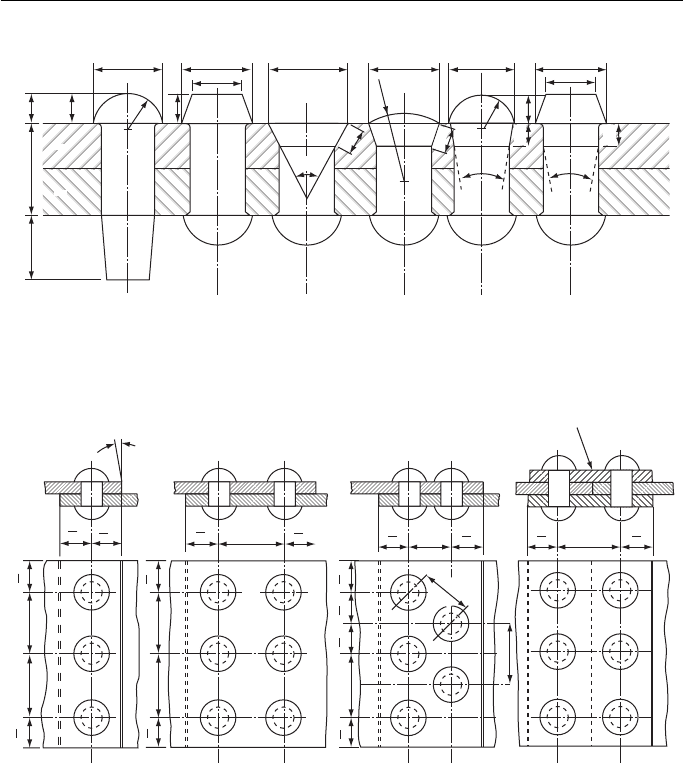
The rivet is usually supplied with one end formed to one of the shapes shown in
Fig. 18.29 . The other end is hammered over and shaped with a tool called a ‘ dolly ’ .
When rivets are used they must be arranged in patterns. The materials to be joined
must have holes drilled in them to take the rivets and these holes weaken the mate-
rial, particularly if they are too close together. If the rivets are placed too close to the
edge of the material the joint will be weakened. The two basic joints are called ‘ lap
and butt joints ’ . Figure 18.30 shows four examples. There is no limit to the number
Locknut
Locknut Slotted
nut 2
split pin
Castle nut
and split
pin
D = Diameter of thread
Self-locking
nut
See Appendix B for proportions of slotted and castle nuts
Double-spring
washer
Nylon or fibre
1
2
D
2
3
D
–
Figure 18.28
Engineering Drawing 297
1 d
1
2
1 d
1
2
1 d
1
2
1 d
1
2
1 d
1
2
1 d
1
2
1 d
1
2
1 d
1
2
1 d
1
2
1 d
1
2
2d 3d
1 d
1
2
3d
1 d
1
2
3d
3d
3d
1 d
1
2
1 d
1
2
1 d
1
2
1 d
1
2
3d
10°
Cover plate or strap
2d + 6 mm
d = Rivet diameter
Single row lap Double row lap Double row zig-zag lap Double cover plate butt
Pitch
Diagonal
pitch
Figure 18.30
60° 15° 15°
0.5d
0.5d
R= 1.5d
Shank Body
tt
Head
0.7d
1.6d 1.6d 1.6d 1.6d 1.6d1.5d
d
d
0.7d
0.5d
0.5d 0.7d
d = Rivet diameter = 1.2 t
Snap head Pan head 60° C’S’K
head
Round
C’S’K head
Snap head
with
tapered neck
Pan head
with
tapered neck
Figure 18.29
of rows of rivets, nor to the number in each row, but the spacing, or pitch of the
rivets, must be as shown.
There are other types of rivet, the most important group being those used for thin
sheet materials. These are beyond the scope of this book and details can be found in
any good engineering handbook.
Keys, Keyways and Splines
A key is a piece of metal inserted between the joint of a shaft or hub to prevent rela-
tive rotation between the shaft and the hub. One of the commonest applications is
between shafts and pulleys.
Geometric and Engineering Drawing298
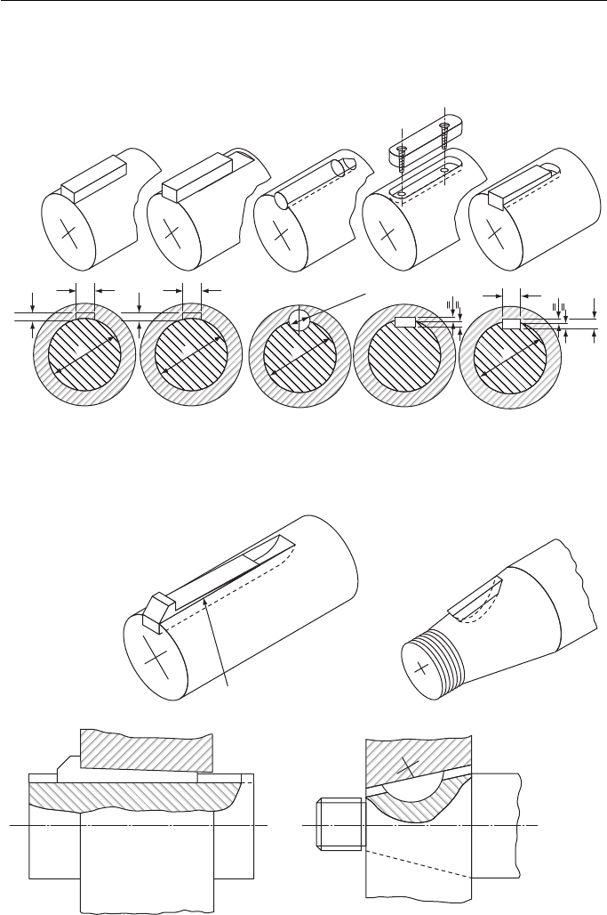
There is a wide variety of keys, designed for light and heavy duties, for tapered
and parallel shafts and to allow or prevent movement of the hub along the shaft ( Figs.
18.31 and 18.32 ).
D
—
4
D
—
12
D
D
—
4
D
—
12
D
D
D
—
6
D
—
6
D
D
—
4
Hollow saddle
(Very light duty)
Flat saddle
(Light duty)
Round
(Light duty)
Feather
(Medium)
Parallel rectangular
(Heavy)
Proportions are approximated for drawing only. For exact dimensions see ISO TC/16.
Figure 18.31
Taper of 1:100
Tapered key–gib head
(Heavy duty, easily removed)
Woodruff key
(For tapered shaft)
Figure 18.32
Engineering Drawing 299
Saddle keys are suitable for light duty only since they rely on friction alone.
Round keys are easy to install because the shaft and hub can be drilled together
but they are suitable for light duty only.
Feather keys and parallel keys are used when it is desired that the hub should slide
along the shaft, yet not be allowed to rotate around the shaft.
Taper keys are used to prevent sliding, and the gib head allows the key to be
extracted easily.
Woodruff keys are used on tapered shafts. They adjust easily to the taper when
assembling the shaft and hub.
The exact dimensions for keys and keyways for any given size of shaft can be
found in ISO TC/16.
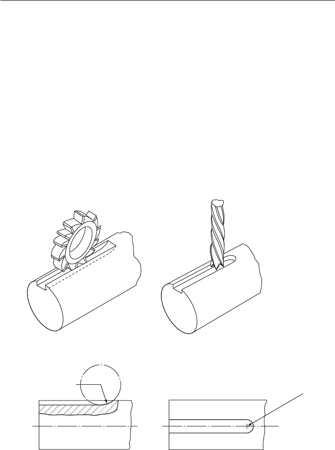
Keyways are machined out with milling machines. If a horizontal milling machine
is used, the resulting keyway will look like the one to the left of Fig. 18.33 . If a vertical
milling machine is used, the resulting keyway will look like the one to the right of Fig.
18.33 . In both cases, the end of the milled slot has the same profile as the cutter.
Keyway horizontally milled
with side and face cutter
Keyway vertically milled
with end cutter
Plan view of keywayVertical section
through keyway
Cutter radius
Cutter radius
Figure 18.33
If a shaft is carrying very heavy loads, it should be obvious that the load is trans-
ferred to the hub (or vice versa) via the key. This means that the power that any shaft
or hub can transmit is limited by the strength of the key. If heavy loading is expected,
Geometric and Engineering Drawing300
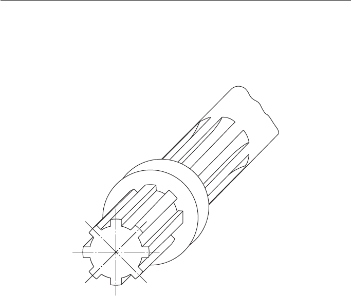
the shaft and hub will be splined ( Fig. 18.34 ). The number of splines will be depen-
dent upon the load to be carried; the greater the number of splines, the greater the
permissible loading.
Splined shaft
and hub
Figure 18.34
Cottered Joints
Keys and splines are used when shafts are subjected to torsional (twisting) loads. If
two shafts have to be joined together and then be subjected to tension or compression
(push – pull), a different type of fastening is needed. One method is to use a cotter.
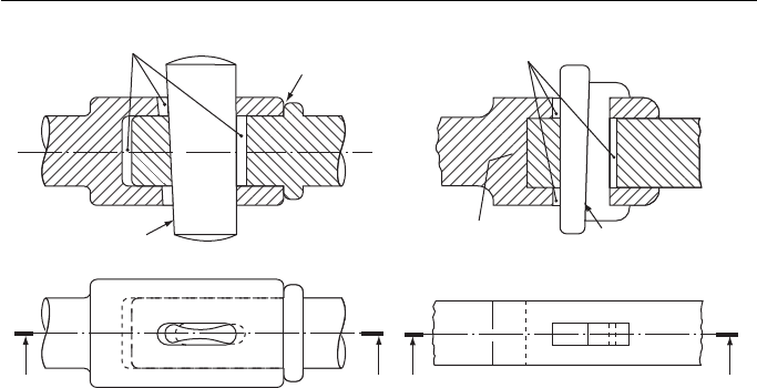
Two examples of cottered joints are shown in Fig. 18.35 . To the left is a connection
for two round shafts, and to the right is the connection for two square or rectangular
shafts.
The whole assembly locks together as follows.
As the tapered cotter is forced downwards it reacts against faces A and B and tries
to draw the shafts together. The smaller shaft cannot be pulled in any further, either
because of the collar at C, or because the shafts meet at D. Thus, the more the cotter
is forced down, the tighter the assembly. The shafts are easily separated by knocking
out the cotter from underneath.
The square or rectangular bar is opened out to form a Y-shaped fork. The smaller
bar fits inside the arms of this Y. A gib is used to prevent the arms from spreading
when the cotter is hammered in. This problem does not arise on round bars because
the larger bar wraps completely round the smaller one.
Engineering Drawing 301
Three Worked Examples
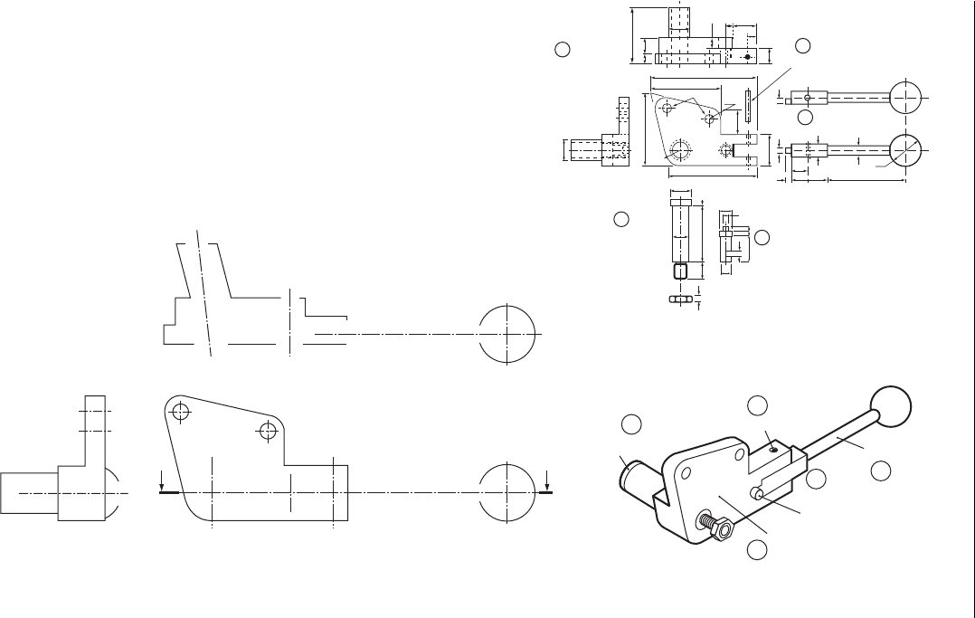
Three examples from examination papers are shown in the following pages. The ques-
tion, as it was set, is shown on one page and opposite is the solution to the question.
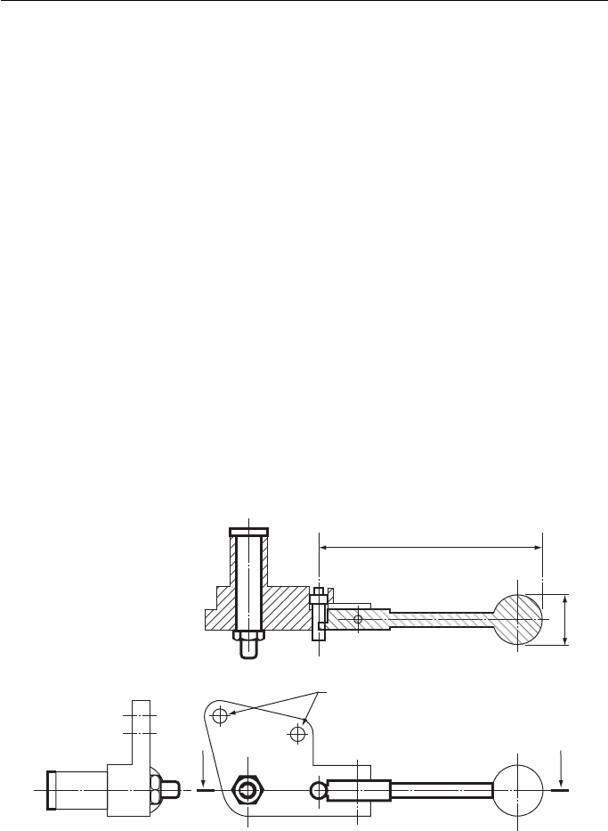
Example 1 shows a question in which the outline is partly completed to save time. The
solution has thin lines for the parts which were given on the paper and thicker lines for
those parts of the drawing which had to be completed by the candidate. This is a fairly
straightforward question except for those parts of the assembly around the left-hand end of
the lever handle and the corresponding cut-out in the gear bracket. The question has to be
studied closely to work out the arrangement of parts on the sectioned view in this region.
Example 2 is interesting because of the number of parts that have to be sectioned,
each requiring a different section line. There are so many parts to be sectioned (nine)
that inevitably one runs out of different types of section lines. Where the same shad-
ing is used twice, the lines have been used on parts that are some distance apart on
the drawing. One could argue about whether or not to section the spindle; normally a
spindle is not sectioned but this one is complicated enough in outline to perhaps jus-
tify sectioning. In fact it has been shown unsectioned.
Example 3 presents an assembly that, without the pictorial illustration, would be
difficult to work out. Part 6 has some interesting cut-outs.
Cottered joint
(For joining round shafts)
Gib and cottered joint
(For joining rectangular shafts)
X
X
Y
Y
B
Clearance
Section X–X
Taper–
(3 mm per 100 mm)
C
A
A
B
A
A
Clearance
D
Section Y–Y
Taper–
(3 mm per 100 mm)
Figure 18.35
Geometric and Engineering Drawing302
1
4
5
2
5
3
Pivot
pin
1
4
3
2
Pivot
pin
Pin
Lever
handle
Change
pin
Gear
bracket
55
1510
φ22
22
8
15
8
30
6
10
φ22
70
R15
Holes φ8
65
85
100
Gear
bracket
R8
25
12
φ8
φ22
φ15
555
φ30
7535
15
5
6
66
25
φ6
φ5
φ12
55
18
4
Pin
30 X φ4
Lever handle
Lathe gear-
change lever
Third angle projection
All dimensions are in millimetres
Change
pin
M10
A
Third angle projection
A
Figure 18.36 Specimen examination question.
Engineering Drawing 303
Example 1
The drawings ( Fig. 18.36 ) show:
(i) A pictorial sketch of a lathe gear-change lever to act as a guide to show how its parts are
fi tted together.
(ii) Details of the various parts of the gear-change lever.
(iii) Partly fi nished views of the gear bracket and lever handle of the lathe gear-change lever.
You are required to do the following:
(a) Complete the front view by adding the parts to make the whole assembly.
(b) Complete the sectional plan on A – A.
(c) Complete the end view.
(d) Print the title GEAR-CHANGE LEVER in letters 6 mm high.
Do not show any hidden detail.
Dimension the following:
(i) The diameter of the knob of the lever handle.
(ii) The total length of the lever handle.
(iii) The two 8 mm holes.
Associated Lancashire Schools Examining Board
Figure 18.37 Scaled solution to Fig. 18.36 which shows a sectioned assembly of a lathe gear
change lever.
2 holes φ8
Gear-change lever
Section A–A
130 mm
φ 30
A
A
