Morling K. Geometric and Engineering Drawing
Подождите немного. Документ загружается.

This page intentionally left blank
Geometric and Engineering Drawing. DOI:
© 2010 Elsevier Ltd. All rights reserved.2010
10.1016/B978-0-08-096768-4.00018-8
18
Engineering Drawing
Introduction
The first step a manufacturer must take when they wish to make an article is to pro-
duce a drawing. First a designer will make a preliminary sketch and then a draught-
sperson will make a detailed drawing of the design. Since neither the designer nor the
draughtsperson will actually make the article, the drawings must be capable of being
interpreted by them in their workshops. These workshops may be sited a long way
from the drawing office, even overseas, and so the drawings produced must be stan-
dardised so that anyone familiar with these standards could make the article required.
Engineering drawing is, therefore, a language. In this modern age of rapid commu-
nication and international buying, from pins to complete atomic power stations, it is
essential for the language to be international. This is the reason why you will often
see symbols used on a drawing instead of words or abbreviations.
BS 308 gives the rules for engineering drawing and should be carefully studied by
every prospective draughtsperson.
The rest of this book tries to explain, within the framework of BS 308, the lan-
guage of engineering drawing.
Type of Projection
The first rule of engineering drawing is to standardise the projection that is used. There
are many to choose from. This book has dealt with three – isometric, oblique and ortho-
graphic. These three are probably the best known. Both isometric and oblique projec-
tions have two big disadvantages. First, it is possible to see only two sides and either
the top or the bottom in any one view. It is, of course, possible to draw more than one
view, but this brings us to the second disadvantage. On any object, except the simplest,
there are curves or arcs or circles. We have seen in Chapters 3 and 6 that, although it is
a fairly simple operation to draw these circles, it takes a considerable amount of time
and, in industry, time costs money. For these reasons, isometric, oblique and like pro-
jections are not used as the standard projection.
The standard projection used is orthographic projection. This is the obvious pro-
jection to use because of its many advantages. It presents a true picture of each face:
circles remain as circles; ellipses remain as ellipses; horizontal lines remain horizon-
tal; and vertical lines remain vertical. There is no limit to the number of views that
you can draw: if the object that you wish to draw is complicated, it is possible to
show half a dozen views; if it is simple, two will suffice. Equally important is the fact
that, however many views are drawn, they are all related to each other in position.

Geometric and Engineering Drawing266
We still need to decide whether to draw in first or third angle orthographic projec-
tion but unfortunately it is impossible to give a definite ruling on this. It is traditional
for the British Isles and the Commonwealth to draw in first angle projection, but the
United States of America and, more recently, the continental countries have adopted
third angle projection. There is no doubt that third angle will become the international
standard. First angle projection is still taught in this country, but students will need to
be familiar with both projections since they may have to answer questions in either.
For full details of both first and third angle projections turn back to Chapter 10.
Sections
Sections have already been discussed at some length in Chapter 10, where their main
application was in finding the true shape across a body. When sections are used in
engineering drawing, although the true shape is still found, the section is really used
to show what is inside the object.
A drawing must be absolutely clear when it leaves the drawing board. The person
or persons using the drawing to make the object must have all the information that
they need presented clearly and concisely so that they are not confused – even over
the smallest point.
Suppose that you had to draw the assembly of the three speed gearbox on the rear
hub of a pedal cycle. You probably know nothing about the interior of that hub. The
reason that you know nothing about it is that you cannot see inside it. If you are to
produce a drawing that can be read and understood by anybody, you can draw as
many views of the outside as you wish, but your drawing will still tell nothing about
the gear train inside. What is really needed is a view of the inside of the hub and this
is precisely what a section allows you to show.
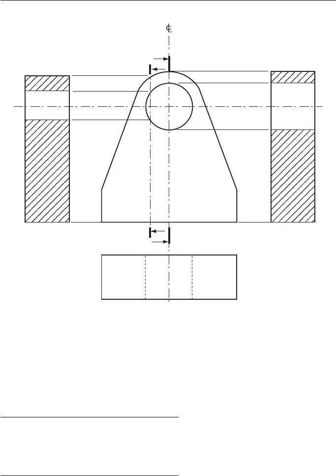
Figure 18.1 shows two sections projected from a simple bracket. You will note
that the sections are both projected from the FE. Sections can be projected from any
elevation – you are not limited to the FE only. Thus, you can project a sectioned FE
from either the plan or the EE. A sectioned EE is projected from the FE and a sec-
tioned plan is projected from the FE. It is not usual to project a sectioned EE from
the plan nor vice versa.
The lines X – X and Y – Y are called the sectional cutting planes and this is a good
description because you are, in fact, pretending to cut the bracket right through along
these lines. Both the sectioned EE are what you would see if you had physically cut
the brackets along X – X and Y – Y, removed the material behind the cutting planes
(i.e. the side away from the arrowheads) and projected a normal EE with the mate-
rial removed. To avoid any misinterpretation, and to show the section quite clearly,
wherever the cutting plane has cut through material the drawing is hatched. The stan-
dard hatching for sectioning is at 45 ° although it will be seen later that in exceptional
circumstances this rule may be broken. You should also note that the cutting plane
passes through the hole in the bracket and this is not hatched. Hatching should only
be done when the cutting plane passes through a solid material.
The lines X – X and Y – Y are of a particular nature. They are chain dotted lines thick-
ened at the end of the chain dotted line. The letters X – X and Y – Y are not a random
Engineering Drawing 267
choice either. Sectional cutting planes are usually given letters from the end of the
alphabet although you will sometimes see other letters used.
Sectioning is a process which should be used only to simplify or clarify a draw-
ing. You should certainly not put a section on every drawing that you do. There
are some engineering details that, if sectioned, lose their identity or create a wrong
impression and these items are never shown sectioned. A list of these items are
shown below.
Nuts and bolts Ball bearings and ball races
Studs Roller bearings and roller races
Screws Keys
Shafts Pins
Webs Gear teeth
Webs are not shown sectioned because section lines across a web give an impres-
sion of solidarity.
The question of clarity arises again when considering an assembly, i.e. more than
one part. If any of the parts are in the above list, they are not hatched, but a finished
product may be composed of several different parts made with several different mate-
rials. In the days when productivity was not quite so vital, the draughtsperson was a
Y
X
Y
X
Section X–X
Section Y–Y
First angle projection
Figure 18.1
Geometric and Engineering Drawing268
person who turned out drawings that were almost works of art. Since there was no
printing as there is today, only one drawing was made. Each different material was
coloured when sectioned and each colour represented a different and specific metal.
Later, when drawings were duplicated, colours were no longer used to any great extent
and each metal was given its own type of shading and it was still possible to identify
materials from the sectioned views. There are now so many types of materials and their
alloys in use that it has become impossible to give them all their own type of line, and
you can please yourself when deciding which line you will use for a particular section.
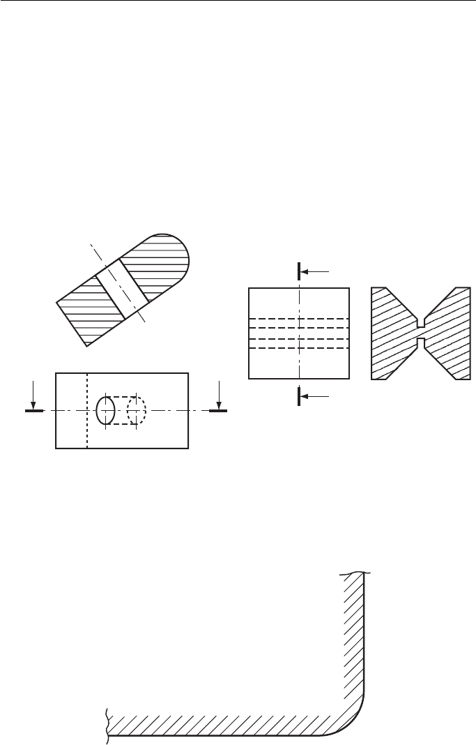
There are occasions when hatching at other than 45 ° is allowable. This is when
the hatching lines would be parallel or nearly parallel to one of the sides. Two exam-
ples of these are shown in Fig. 18.2 .
YY
Z
Z
Third angle projection
Section Y–Y
Section Z–Z
Figure 18.2 Hatching lines other than 45 ° .
If a very large piece of material has to be shown in section, then, in order to save
time, it is necessary to hatch only the edges of the piece. An example of this is shown
in Fig. 18.3 .
Figure 18.3 Hatching lines for large bodies.
Engineering Drawing 269
If the object that you are drawing is symmetrical and nothing is to be gained by
showing it all in section, then it is necessary to show only as much section as the
drawing requires. This usually means drawing a half-section.
Remembering that sections are used only to clarify a drawing, it is quite likely
that you will come across a case where only a very small part of the drawing needs
to be sectioned to clarify a point. In this case a part or scrap section is permitted. Two
examples of this are shown in Fig. 18.4 .
X
X
Scrap section
across X–X
Figure 18.4 Part or local sections.
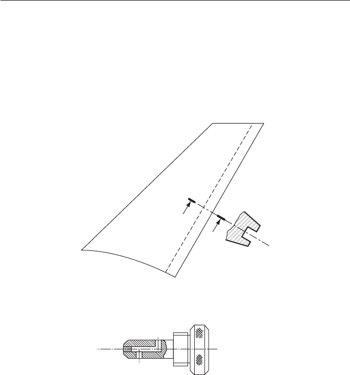
It is often necessary to show a small section showing the true shape across an
object. There are two ways of doing this and they are both shown in Fig. 18.5 . The
revolved section is obtained by revolving the section in its position and breaking the
outline to accommodate the section. The removed section is self-explanatory and
should be used in preference to the revolved section if there is room on the drawing.
It is so very much neater.
When very thin materials have to be shown in section and there is no room for
hatching, then they are shown solid. The most common occurrence, of course, is
when drawing sheet metal. If two or more parts are shown adjacent, a small space
should be left between them ( Fig. 18.6 ).
Geometric and Engineering Drawing270
Revolved section
Local section
Figure 18.5
Figure 18.6 Sectioning thin materials.
Engineering Drawing 271
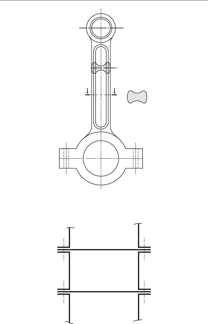
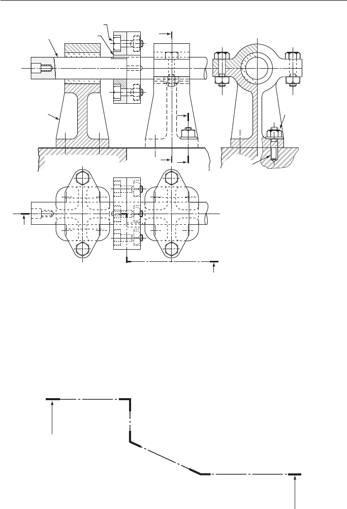
Figure 18.7 attempts to show, in a completely hypothetical arrangement, as many
details as possible about sectioning on one drawing. The drawing shows two lengths
of shaft joined by keyed flanges which are bolted together. The shafts are supported
by two identical plummer blocks which are, in turn, bolted to the base via four studs
for each block. Only one stud is shown on the drawing. This is common practice on
a complicated drawing when, rather than simplifying the drawing, it is complicated
by too much detail.
Figure 18.8 Changes in direction of a section line.
Shaft
Key
Bolt
Y
First angle projection
Section X–X
Web
Z
Y
X
X
Z
Half section on Y–Y
Nut
Scrap section Z–Z
(Only one holding
stud shown for
clarity)
Stud
Figure 18.7
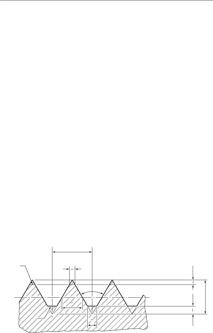
Note how the section line is thickened where it changes direction, as shown in
Fig. 18.8 .
Geometric and Engineering Drawing272
Screw Threads
The screw thread is probably the most important single component in engineering. The
application of the screw thread to nuts, bolts, studs, screws, etc., provides us with the
ability to join two or more pieces of material together securely, easily and, most impor-
tantly of all, not permanently. There are other methods of joining materials together
but the most widely used ones – riveting, welding and (very common these days) using
adhesives – are all permanent. It is true that these methods are cheaper, but when we
know that we might have to take the thing apart again we use the screw thread. Since
the screw thread is so important it is well worthwhile looking at the whole subject more
closely.
The standard thread, in this country, for many years was the Whitworth; this thread
was introduced by Sir Joseph Whitworth in the 1840s. It was the first standard thread;
previously a nut and bolt were made together and would fit another nut or bolt only by
coincidence. At the time, it was a revolutionary step forward.
The BSW (British Standard Whitworth) thread and its counterpart the BSF
(British Standard Fine) thread were the standard threads in this country until metri-
cation and will probably be in use for many years.
However , the United States of America developed and adopted the u nified thread
as their standard and countries using the metric system of measurement had their
own metric thread forms. It became increasingly obvious that an international screw
thread was needed.
As far as this country was concerned, the breakthrough came when it was decided
that British Industry should adopt the metric system of weights and measures. The
International Standards Organisation (ISO) has formulated a complex set of stan-
dards to cover the whole range of engineering components.
Their thread, the ISO, is now the international standard thread. The ISO and uni-
fied thread profiles are identical. The unified thread is the Standard International
thread for countries which are still using imperial units.
The ISO basic thread form is shown in Fig. 18.9 .
Crest
Root
Root
Pitch
60°
H = 0.866 P
H
4
H
8
P
8
P
2
P
4
P
2
P
4
Figure 18.9 Basic form of ISO thread.
Engineering Drawing 273
You will note that the thread is thicker at the root than at the crest. This is because
the stresses on the thread are greater at the root and the thread needs to be thicker
there if it is to be stronger.
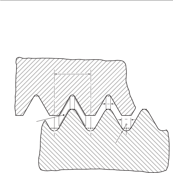
In practice, since there is nothing gained by having the root and crest of a nut and
bolt in contact, and because ‘ square ’ corners are difficult to manufacture, the ISO
thread form is usually modified to that shown in Fig. 18.10 .
P
P
Nut
(Internal thread)
Area of
thread in contact
Bolt
(External thread)
P
8
P
4
0.1443 P
0.1443 P
Figure 18.10 ISO thread used in practice.
You can see that the contact will be only on the flanks.
There is more than one type of ISO thread. There are 12 series of threads ranging
from the widely used coarse thread series, which is used on bolts from 1.6 to 68 mm
diameter, to a 6 mm constant pitch series with sizes from 70 to 300 mm diameter. The
whole range of thread series has the same basic profile and full details can be found
in BS 3643. The fine thread series (the equivalent to the redundant BSF) ranges from
1 · 8 to 68 mm.
