Mench M.M. Fuel Cell Engines
Подождите немного. Документ загружается.

c04 JWPR067-Mench January 28, 2008 17:28 Char Count=
160 Performance Characterization of Fuel Cell Systems
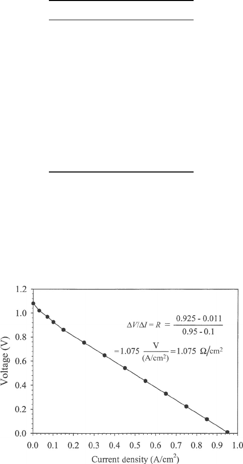
Current Density
a
Vo l t a g e
0 1.08
0.03 1.02
0.07 0.968
0.1 0.925
0.15 0.861
0.25 0.754
0.35 0.648
0.45 0.542
0.55 0.436
0.65 0.329
0.75 0.223
0.85 0.117
0.95 0.011
a
Data from [13].
completely appropriate, this behavior is approached for a high-temperature fuel cell in the
low to moderate current density regimes.
A solution can be found by solving for the slope of the polarization curve in the main
linear region. First, plot the polarization curve and select the appropriate region. In this case,
because it is a high-temperature fuel cell operating on hydrogen, the overall polarization
curve is quite linear and dominated by ohmic effects.
COMMENTS: This technique should be a maximum possible value for the ohmic re-
sistance, because we have assumed that the slope in the middle region of the polarization
curve is solely a result of ionic losses. In fact, activation and concentration polarization
losses also contribute to the voltage loss in this region, although for these high-temperature
fuel cells the approximation is very close. There are other experimental techniques to more
accurately obtain the ohmic resistance in the cell. Some of these methods are discussed in
Chapter 8 on experimental methods.

c04 JWPR067-Mench January 28, 2008 17:28 Char Count=
4.3 Region II: Ohmic Polarization 161
Electrolyte—ionic conductivity only
Catalyst layer—mixed conductivity
Catalyst layer—mixed conductivity
x
0
δ
CL
δ
CL
δ
e
Figure 4.28 Schematic of electrodes and main electrolyte in generic fuel cell system.
For a well-built fuel cell, the dominating ohmic polarization, η
R
, is from the electrolyte.
This includes the ionic transport resistance in both the main electrolyte separator and
the electrodes, since the electrodes will have ionic (and electronic) conduction as well.
Otherwise, reactions occurring in the electrode could not conduct the ions through the
electrolyte. Even though the catalyst layer in most fuel cells is only on the order of 5–30 µm,
the mixed conductivity and highly porous nature can result in a significant contribution to
the overall ohmic drop of the fuel cells. The reaction in the catalyst layer not only is at the
surface facing the flow field but is also distributed throughout the three-dimensional porous
structure. The distribution of current throughout the three-dimensional porous structure of
the catalyst layer is a complex issue that is a function of ionic and electronic conductivity,
reactant concentration, catalyst distribution, and other factors beyond the scope of this
text. In many models, the reaction distribution of the catalyst layer is assumed to occur in
a single plane due to the thinness of the catalyst layer. A simplification can be made to
allow us to estimate the resistance losses in the electrode if we assume the average location
of the reaction in the electrode is at the dashed line in Figure 4.28, representing the half
distance through the electrode. This implies a homogeneous current distribution throughout
the thickness of the electrode structure. The effective electrode ionic conductivity can be
written as [14]
σ
i,eff
=
σ
i,eff
ε
electrode
τ
(4.76)
where τ is the electrolyte tortuosity, which was determined to be approximately 1 [15] for
PEFCs. In Eq. (4.76), ε
electrolyte
is the volume fraction of electrolyte in the catalyst layer,
which is typically 10–30% in PEFCs. This concept is illustrated in Example 4.7.
Contact Resistance Contact resistance is a result of imperfectly matched material inter-
faces in the fuel cells. At every location where there is a noncontinuous contact between
dissimilar materials, there is an electronic or ionic contact resistance, as illustrated in
Figure 4.29. The contact resistance is a function of the material surface state and roughness
and the contact pressure between the materials (values of area contact resistance are given
in units of ·m
2
or ·cm
2
):
R
contact
=
V
loss
i
( · cm
2
) (4.77)
R
contact
=
V
loss
iA
contact
() (4.78)
where A
contact
is the contact area between the two surfaces. This leads to an interesting
engineering trade-off in channel design, illustrated in Figure 4.30. The smaller the landing
c04 JWPR067-Mench January 28, 2008 17:28 Char Count=
162 Performance Characterization of Fuel Cell Systems
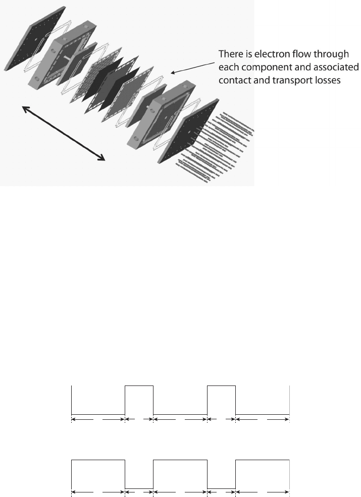
Figure 4.29 Schematic of single PEFC assembly, illustrating all contact surfaces. (Image courtesy
of Joseph Scott [16].)
areas, the greater the area available for mass transport, and the lower the flow channel
pressure drop for the same flow rate. However, the smaller the landing area, the higher
the ohmic drop from contact resistance. Therefore, a balance including this and other
competing factors is sought for fuel cell design. Major factors in contact resistance include
the following:
1. State of Contact Surface If contacts are oxidized, as can occur over time in a
oxidative environment, this factor can become significant. Special coatings on metal
contacts can be used, such as gold or nitrides that resist surface oxidation.
2. Compression Pressure from Current Collector onto Electrode or Diffusion Me-
dia In larger cells, it is difficult to achieve an ideal state of uniform compression,
and current collection can be biased toward locations with better contact.
C
L
L = 2C
(a)
C
LL
CLCLC
C = 2L
(b)
Figure 4.30 Illustration of trade-off between contact resistance transport. Typical channel to land
ratios in fuel cells range from 1 : 1 to 3 : 1. (a) Wide land, low contact resistnace. (b) Narrow land,
high contact resitance.

c04 JWPR067-Mench January 28, 2008 17:28 Char Count=
4.3 Region II: Ohmic Polarization 163
3. Tolerance and Flatness of Individual Fuel Cell Bipolar Plates To achieve a uni-
form compression on a stack that can have as many as 300 fuel cells in series, a
very tight manufacturing tolerance on the flatness of individual bipolar plates must
be achieved. The change in a hundred or so micrometers can have a major effect on
the distributed contact resistance.
Example 4.7 Cell Ohmic Loss Limiting Current Calculation Consider an ideal PEFC
with only the ionic ohmic losses in the electrolyte and catalyst layers. Ignore kinetic, elec-
tronic, and other losses for this problem. The OCV is 1.0 V, and the electrolyte conductivity
σ
e
is 8.3 S/m. The catalyst layers can be assumed to be 40% ionomer equivalent and 30
µm thick.
Consider two cases:
(a) The electrolyte is Nafion 112, which is 51 µm thick.
(b) The electrolyte is Nafion 117, which is 178 µm thick
Find the maximum current density that each electrolyte can support, ignoring other polar-
izations besides ohmic losses.
SOLUTION From Ohm’s law
R = ρ
l
A
=
l
σ A
V = I
R = iA
R = i
A
l
σ A
= i
l
σ
i
max,112
= V
l
a
σ
a
I
+
l
e
σ
e
II
+
l
c
σ
c
III
−1
= (1.0J
C)
15 × 10
−6
m
0.4 × 8.3S
m
+
51 × 10
−6
m
8.3S
m
+
15 × 10
−6
m
0.4 × 8.3S
m
−1
1m
2
10,000 cm
2
= 6.58 A/cm
2
where I, II, and III represent the ionic resistances in the anode catalyst layer, main electrolyte,
and cathode, respectively. The ionic conductivity of the electrodes is reduced by the ionomer
fraction via Eq. (4.76), and the average location of the reaction in the electrodes is assumed
to occur midway through the catalyst layer.
For the Nafion 117 electrolyte
i
max,117
= V
l
a
σ
a
+
l
e
σ
e
+
l
c
σ
c
−1
= (1.0J
C)
15 × 10
−6
m
0.4 × 8.3S
m
+
178 × 10
−6
m
8.3S
m
+
15 × 10
−6
m
0.4 × 8.3S
m
−1
1m
2
10,000 cm
2
= 3.28 A/cm
2
c04 JWPR067-Mench January 28, 2008 17:28 Char Count=
164 Performance Characterization of Fuel Cell Systems
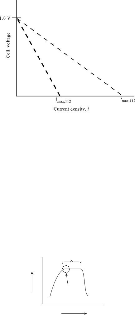
As we expect, the thicker electrolyte supports a significantly lower maximum current
density. Based on ohmic losses only, if we plotted the predicted polarization curves, they
would look as follows:
COMMENTS: Although low-temperature PEFCs tend to be limited by reactant availabil-
ity (concentration polarization), many high-temperature fuel cells are ultimately limited by
the ionic conductivity of the electrolyte, because mass transport and kinetics are facilitated
at high temperature (e.g., see polarization curve in Example 4.6). Also, note the relative
importance of the electrolyte in the overall loss. Considering that some PEFC electrolytes
can be as thin as 18 µm, the electrode resistance can even be larger than that of the main
electrolyte. Also it should be noted that the use of ionomer percentage to adjust ionic
conductivity is an approximation, as well as the approximation that reaction occurs in the
middle of the catalyst layer. More complex modeling of these reactions and losses are
available in literature but are beyond the scope of this text.
Cell Assembly In terms of the compression pressure on the fuel cell, there are initially high
benefits to increased compression and reduced contact resistance. Think of a stack loosely
held together by gravity. Contact losses would obviously be high, as shown in Figure 4.31.
As the compression is increased, there is a plateau region where optimal contact pressure is
reached. If the compression is increased too far beyond this level, however, the components
in the fuel cell will suffer plastic (permanent) deformation and cause a very sharp drop-off
Cell voltage
Compression pressure
Plateau region
Desired
design point
Figure 4.31 Cell performance at given current as function of stack compression pressure.
c04 JWPR067-Mench January 28, 2008 17:28 Char Count=
4.3 Region II: Ohmic Polarization 165
in performance that is not recoverable. In a brittle fuel cell or one with significant thermal
expansion of the materials such as the SOFC, thermal and compressive stresses can result
in catastrophic failure of components. Different types of fuel cells obviously have different
material limits for plastic deformation, but the qualitative shape is the same as Figure 4.31.
For low-temperature fuel cells, the presence of liquid water does not influence the contact
resistance since pure water is nonconductive.
Over time, various components may deform to relax the compression stress in the ma-
terials, loosening contacts. Some stacks are designed to be spring loaded at the endplates to
provide consistent compression. Also, since each channel design is different, with different
channel-to-land ratios, it is impossible to state an optimal compression pressure for a fuel
cell. For PEFCs, the compression pressure of 1–2 MPa is generally appropriate, but the
optimal compression pressure must be determined experimentally for a given fuel cell and
components. In general, several criteria can be used to determine the best compression on
a cell or stack:
1. Prescribed Torque or Spring Loading Imposed on All Compression Bolts or Tie-
Downs This method is common in laboratories with single cells. However, this
method is highly unreliable and can lead to significant variation in compression
pressure and uniformity, since the compression torque is a function of the inter-
facial friction on the bolt threads or between the nut and washer and the back
compression plate. In general, this method should only be used with caution on a
well-characterized fuel cell.
2. Compression Gap Width The materials under compression will have a measurable
gap width decrease under compression, and the compression force on the fuel cell is
increased until a desired elastic deformation is achieved in the stack. For example,
in the PEFC, many diffusion media work best when compressed by 10–20% of
their original thickness. Another advantage is that the gap width can be measured
at locations around the periphery to ensure uniformity of compression.
3. Compression Pressure Specification The compression pressure of the flow field on
the fuel cell is prescribed. The compression pressure can be determined experimen-
tally with a load cell inserted in the fuel cell or with pressure-sensing contact paper
as shown in Figure 4.32. The proper compression pressure can then be correlated
with the measured gap width or bolt torque.
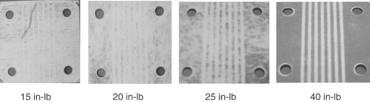
Figure 4.32 Pictures of Pressurex pressure-sensing paper used to measure contact pressure distri-
butionin5-cm
2
fuel cell with different torque on fuel cell bolts. The higher the compression, the
better the electrical contact. At some point, however, the cell will become overcompressed.
c04 JWPR067-Mench January 28, 2008 17:28 Char Count=
166 Performance Characterization of Fuel Cell Systems
In practice, large stacks of hundreds of cells are assembled using large automated presses
to ensure uniformity of assembly and proper cell sealing.
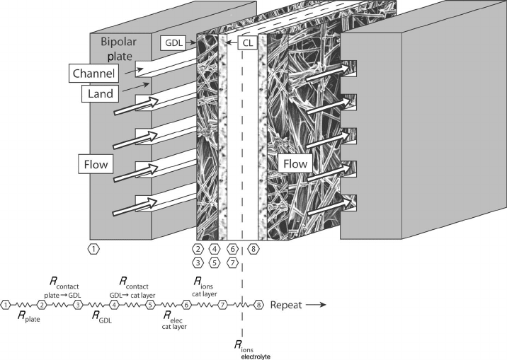
Example 4.8 Equivalent Ohmic Loss Thermal Network Draw an equivalent ionic
resistance network for a single PEFC.
SOLUTION
COMMENTS: The cell and resistance network above shows all the resistances present,
electronic and ionic. Note the mixed ionic and electronic conductivity required in the
catalyst layer. In most cases except the catalyst layer, the electronic resistance is negligible.
Of the various contact resistances, the electronic contact resistance between the land and
diffusion media tends to become dominant for PEFCs [17].
Example 4.9 Resistance Calculation Consider a PEFC operating at 0.6 V, 1 A/cm
2
,
with 500 cm
2
active area electrodes. Nafion 112 (51-µm) electrolyte and a graphite current
collector are used, with 3-mm-thick current collection plates, a 200-µm GDL on the anode,
and a 300-µm GDL on the cathode. The catalyst layers are 10 µm thick on the anode and
20 µm on the cathode and can be approximated as 0.3 fraction ionomer on the anode and
0.35 fraction ionomer on the cathode. The electrolyte ionic conductivity can be assumed
to be 8.3 S/m. The landing to channel area ratio is 1 : 2, and the measured total contact
resistance is 30 m · cm
2
(a) Estimate η
R
, the voltage loss from resistance.
(b) Estimate the percentage of total potential power wasted due to ohmic losses at this
condition if E
th
= 1.25 V.

c04 JWPR067-Mench January 28, 2008 17:28 Char Count=
4.3 Region II: Ohmic Polarization 167
SOLUTION
(a) We can neglect the electronic resistance in most cases relative to the ionic resis-
tance:
η
R
= iA
n
j=1
R
i
= iA(R
anode
+ R
cathode
+ R
electolyte
+ R
contact
+ R
electric
≈ 0)
Plugging in the equations and the current and active area,
η
R
= iA
n
j=1
R
i
= (1 A/cm
2
)(500 cm
2
)
1
σ
a
A
+
1
σ
e
A
+
1
σ
c
A
+
R
contact
A
contact
The contact area is one-third of the active area since the landing to channel ratio is
1: 2:
η
R
= iA
n
j=1
R
i
= (500 A)
(5 × 10
−6
m) · (10,000 cm
2
/m
2
)
(0.3 × 8.3 · m)(500 cm
2
)
+
(51 × 10
−6
) × 10,000
8.3 × 500
+
(10 × 10
−6
) × 10,000
0.35 × 8.3 × 500
+
0.03
166.6
· cm
2
cm
2
Resulting in:
η
R
= 0.205 V
(b) We can simply compare the electrical power at a condition with no losses to the
condition including our calculated ohmic losses:
P
1
= IV = 1.25 V · 500 A = 625 W
P
2
= IV = 1.044 V · 500A = 522.0W
Wasted =
(
625 − 522
)
625
= 16.48%
COMMENTS: At a relatively high current density of 1 A/cm
2
, we see that the ohmic
losses are very significant. For a PEFC, the ionic conductivity of the electrolyte is a strong
function of humidity. Lower humidity values greatly increase the impact of ohmic losses,
steepening the slope of the ohmic drop on a polarization curve.
Returning to our ultimate goal of being able to analytically describe the fundamental
physics of the polarization curve, we now have an expression that includes the starting
equilibrium voltage, the departure from this voltage resulting from activation overpotential
at each electrode, and the ohmic polarization:
E
cell
= E
◦
(T , P) − η
a,a
−
η
a,c
− η
r
Can now solve
−η
m,a
−
η
m,c
− η
x
(4.79)
The only remaining major losses are a result of reactant crossover and concentration
polarization, discussed in the following sections.

c04 JWPR067-Mench January 28, 2008 17:28 Char Count=
168 Performance Characterization of Fuel Cell Systems
4.4 REGION III: CONCENTRATION POLARIZATION
Concentration polarization is caused by a reduction in the reactant surface concentration,
which reduces the thermodynamic voltage from the Nernst equation and the exchange
current density from the BV equation. Figure 4.33 illustrates the transport of reactants from
the flow channel to the reaction surface in a PEFC. The transport of species in the fuel cell
is discussed in detail in Chapter 5. For now, we consider the effects of reduced reactant
availability at the surface. At the electrode surface, reaction consumes fuel and oxidizer
at the rate determined from Faraday’s law. A rate of transport of reactant must be at least
equal to this or concentration polarization will develop:
˙
n
consumed
=
iA
nF
≤
˙
n
transport
(4.80)
Restriction of the rate of transport to the electrode can occur for a variety of reasons:
1. Gas-Phase Diffusion Limitation The diffusion of reactant in the gas phase is
limited to some value. In principle, we can imagine that there is a maximum rate
that perfume can diffuse from the front of a room to the back of the room. Now
consider the perfume is being consumed at the back of the room. The consumption
rate would be limited to the maximum perfume diffusion rate, as the reaction rate
is limited by reactant availability. At the double layer, a greater polarization will be
required to attract the required adsorbed species for reaction in a limiting condition.
2. Liquid-Phase Accumulation and Pore Blockage Limitation In low-temperature
fuel cells such as the PEFC, liquid water accumulation and blockage in the pores
of the electrolyte, diffusion media, or flow channels of the anode or cathode can
reduce the transport rate of reactant to the catalyst. Voltage loss by this phenomenon
is generically termed flooding. This topic is discussed in greater detail in Chapters 5
Figure 4.33 Schematic of path through diffusion media to catalyst layer in PEFC.

c04 JWPR067-Mench January 28, 2008 17:28 Char Count=
4.4 Region III: Concentration Polarization 169
and 6. In liquid electrolyte systems such as the MCFC or PAFC, improper electrolyte
control can also restrict reactant access to catalyst sites.
3. Build-up of Inert Gases This is also a gas-phase limitation but is a result of the
accumulation of nonparticipating inert species such as nitrogen. As the oxygen is
consumed in an air cathode, the nitrogen mole fraction increases. Near the electrode,
the nonparticipating species can form an inert boundary-layer-restricting reaction.
4. Surface Blockage by Impurity Coverage In this case, some impurity becomes
adsorbed on reaction sites, preventing adsorption of the desired reactant. This is
commonly seen in low-temperature fuel cells when a CO impurity is present.
Carbon monoxide preferentially adsorbs on platinum catalyst sites in the anode
and has a very high polarization for oxidative removal.
In Chapter 3, we learned that the Nernst equation could be used to predict the change in
equilibrium voltage from concentration changes of the reactants and products. At the time,
we noted that there was also a kinetic effect of the concentration. Once there is reaction
at the electrode, the system is not in thermodynamic equilibrium and these effects must
be considered. From a combination of the thermodynamic (Nernst) and exchange current
density dependency [Eq. (4.31)], the voltage adjustment as a result of the change in oxygen
concentration from the reference value (1 atm) on the cathode can be shown as
V
s,ref
=
R
u
T
2F
ln
C
O
2
,s
C
O
2
,ref
1/2
+
R
u
T
F
ln
C
O
2
,s
C
O
2
,ref
γ
O
2
(4.81)
where γ is the ORR order with respect to O
2
partial pressure at constant overpotential and
ranges between 0.6 and 0.75 for a PEFC [9]. Assuming γ ∼ 0.75, the two can be combined
into the following:
V
s,ref
=
R
u
T
F
ln
C
O
2
,s
C
O
2
,ref
(4.82)
This predicts a 47-mV gain in potential for switching from dry air (21% O
2
) to pure oxygen
at 353 K, a value that matches experimental data well [9].
On the anode, we can write
V
s,ref
=
R
u
T
2F
ln
C
H
2
,s
C
H
2
,ref
+
R
u
T
F
ln
C
H
2
,s
C
H
2
,ref
γ
H
2
(4.83)
where the reaction order for hydrogen is 0.25–1.0. In practice, the anode hydrogen concen-
tration effect is often neglected for several reasons:
1. The diffusivity of hydrogen is much more rapid than oxygen, especially in higher
temperature fuel cells, so that transport limitation is rare.
2. The HOR kinetics are facile compared to the cathode so that the cathode polarization
typically dominates.
3. In PEFCs, liquid blockage (electrode flooding) occurs more frequently on the cath-
ode, so that two-phase effects can be mostly ignored for low-temperature fuel cells
at the anode and completely ignored for high-temperature fuel cells.