Mattingly J.D., Heiser W.H., Pratt D.T. Aircraft Engine Design
Подождите немного. Документ загружается.

326 AIRCRAFT ENGINE DESIGN
Of the three principal components of a gas turbine engine--the compressor,
combustor, and turbine--the combustor is usually perceived to be the least under-
stood, perhaps even a "black art," component, and the same can be said of the fourth
component of some engines, the afterburner. This is because most propulsion-
oriented students and engineers have not had the opportunity to study all of the
engineering subjects that are required to understand, analyze, and design combus-
tors and afterburners.
Because there are no rotating parts in the combustor and afterburner to transfer
external work to or from the gas stream, the only work and power relations required
are those which determine how much mechanical power must be dissipated in order
to cause the vigorous mixing required by the combustion process. Consequently,
students who are familiar with the analysis and design of rotating machinery will
be reasonably comfortable dealing with the processes of velocity diffusion, liner
wall cooling, jet mixing, total pressure loss, and air partitioning in the combustor.
However, in order to understand the equally essential processes of heat re-
lease, flameholding, and pollutant formation and control, students must have some
background in three additional engineering subjects, namely, 1) chemical thermo-
dynamics of ideal gases, 2) gas-phase chemical kinetics, and 3) chemical reactor
theory. Essential concepts from these three topics are presented in summary form
in this chapter. Supporting design and analysis computer programs are included in
AEDsys, the suite of software tools that accompanies this textbook.
Unlike the study of rotating machinery, there are surprisingly few resources in
the open literature that deal with the design of main burners and afterburners in
airbreathing propulsion systems. For more in-depth information two recommended
sources are Arthur Lefebvre's
Gas Turbine Combustion 2
for the main burner and
Edward E. Zukoski's "Afterburners. ''3
9.1.1 Combustion Systems Components
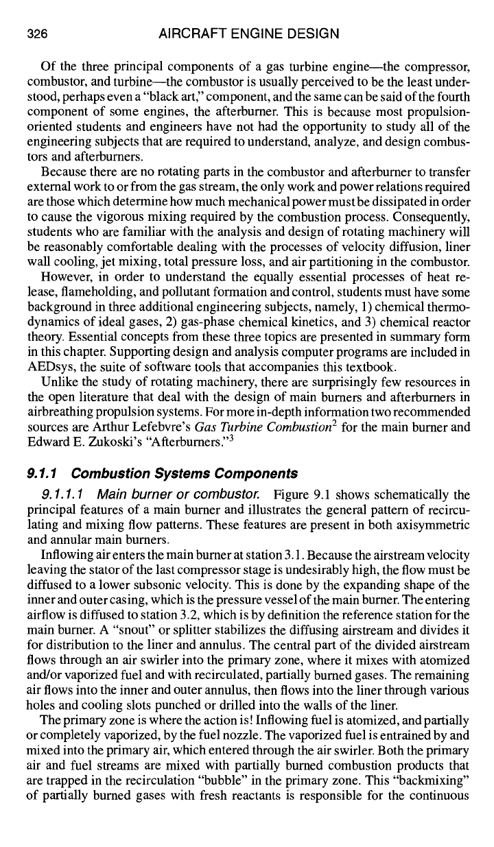
9.1.1.1 Main burner or combustor. Figure 9.1 shows schematically the
principal features of a main burner and illustrates the general pattern of recircu-
lating and mixing flow patterns. These features are present in both axisymmetric
and annular main burners.
Inflowing air enters the main burner at station 3.1. Because the airstream velocity
leaving the stator of the last compressor stage is undesirably high, the flow must be
diffused to a lower subsonic velocity. This is done by the expanding shape of the
inner and outer casing, which is the pressure vessel of the main burner. The entering
airflow is diffused to station 3.2, which is by definition the reference station for the
main burner. A "snout" or splitter stabilizes the diffusing airstream and divides it
for distribution to the liner and annulus. The central part of the divided airstream
flows through an air swirler into the primary zone, where it mixes with atomized
and/or vaporized fuel and with recirculated, partially burned gases. The remaining
air flows into the inner and outer annulus, then flows into the liner through various
holes and cooling slots punched or drilled into the walls of the liner.
The primary zone is where the action is! Inflowing fuel is atomized, and partially
or completely vaporized, by the fuel nozzle. The vaporized fuel is entrained by and
mixed into the primary air, which entered through the air swirler. Both the primary
air and fuel streams are mixed with partially burned combustion products that
are trapped in the recirculation "bubble" in the primary zone. This "backmixing"
of partially burned gases with fresh reactants is responsible for the continuous
DESIGN: COMBUSTION SYSTEMS 327
Outer casing
/
1
Jl
Dilution hole
Transition duct
Air
swider Liner
\Dome
Fuel nozzle ~ ~ /
Cooling slot
10utarinnu'us L,,
.~..,~¢~ Secondary hole
Diffuser ~ Primary zone
I
Secondary or
Intermediate
zone I
J ~.,,
Inner annulus
station 3.1 station 3.2 Inner
casing
a) Principal features
statiJ~n 3.9
I Dilution
zone
station
4
micromixed I~
I I /reaction zone --7 --~ annulus flow
[
dilution
"111
I primary
"~ '/-//-if/J/ ~'~'"
airflow •
\airflow
I I I air flow
/. "
" - - ~ "
-- \~ ', "~"
--
i t....-.=...--= , ~ , recirculati,~,, J \
~1_ fuel flow ( (7low ,~r /' ; ......
I~A
~, \'-
~ , ~
/
linerflow
- \y, >
--.
cooli'n;:irflow ~~( J 1/
b) Flow patterns
Fig. 9.1 Main features and flow patterns of the main burner/combustor: a) Principal
features; b) Flow patterns.
self-ignition process called flameholding, so that an external source of ignition,
such as a spark plug, is not required. (However, an external ignition source is
required for starting the ftameholding process.) Chemical reaction occurs primarily
in the micromixed reaction zone, within which reactants have been mixed to near-
molecular homogeneity.
From the primary zone the mixture of partially mixed, actively burning, and
incompletely burned gases flows downstream into the secondary or intermediate
zone, where they continue to bum towards completion while mixing with inflow-
ing air from the secondary holes. Two processes must occur in parallel in the
secondary/intermediate zone: 1) the primary zone effluent gases must continue to
burn out, and 2) the in-mixing secondary air must "lean out" (reduce the fuel-air
ratio of) the liner gas stream. These two processes must be balanced in such a way
that the temperature rise which would otherwise occur from continued burnout is
offset by a temperature decrease which would otherwise occur as a result of the de-
crease in fuel-air ratio. Consequently, the liner gases flow through the intermediate

328 AIRCRAFT ENGINE DESIGN
zone at essentially constant temperature, and combustion should be complete when
the liner gas reaches the downstream end of the intermediate zone.
The dilution zone process, by comparison with the complex chemical and phys-
ical processes occuring in the primary and intermediate zones, is a "no-brainer."
All that is required of the dilution zone is that any remaining annulus airflow be
dumped through the dilution holes into the liner hot gas stream, with just sufficient
stirring to avoid hot spots forming on the first-stage high-pressure turbine stators
(nozzles).
After the hot gases exit the combustor liner at station 3.9, they are accelerated
through a converging transition duct until they are choked at the throat of the first
stage high-pressure turbine nozzles downstream of station 4.
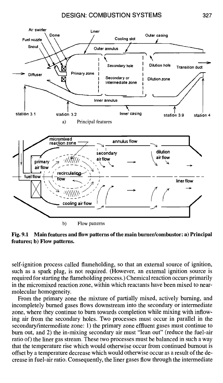
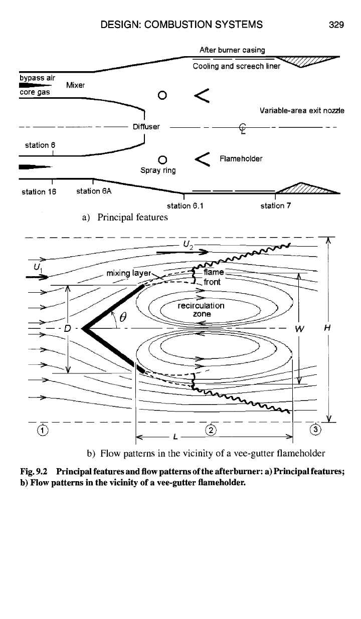
9.1.1.2 Afterburner or augmenter.
Figure 9.2a shows schematically the
principal features of an afterburner, and Fig. 9.2b illustrates the general pattern of
recirculating and mixing flow patterns. The geometry in Fig. 9.2a is axisymmetric
about the engine axis, but Fig. 9.2b is planar.
As shown in Fig. 9.2a, the core gas and bypass air enter the mixer at station 6
and station 16, respectively. The core gas is composed of combustion products.
Although the core gases have given up a considerable amount of thermal energy to
work extraction in the turbine, they still contain a considerable amount of thermal
energy and excess oxygen. Mixing the bypass air with the core gas increases the
tool fraction of oxygen available for reburning, and the hotter core gas warms up
the cooler bypass air as well. The two gas streams are mixed adiabatically and
slightly diffused by station 6A.
While the (core gas + bypass air) mixture is being slowed in the diffuser, fuel
is injected and atomized by the spray rings. The flow rate of fuel is designed to
produce the highest possible temperature at the afterburner exit. By the time the
(fuel ÷ core gas ÷ bypass air) mixture enters the afterburner flameholding region
at station 6.1, it is well-mixed to near-molecular level, so that combustion can take
place.
As shown in Fig. 9.2b, after the combustible gas mixture passes over the down-
stream edge of the vee-gutter flame holders, it then entrains fully burned, hot
combustion products from the recirculation zone in a shear-driven mixing layer.
At some point sufficiently far downstream, a standing flame front is established.
Just downstream of the standing flame front, the shear-driven mixing layer disen-
trains a portion of the burning gases. The disentrained gases then reverse direction
and flow upstream inside the bubble of the recirculation zone, where there is suf-
ficient residence time for them to burn to near completion. The remaining, outer
portion of the burning gases behind the standing flame front propagates a turbulent
flame front outward through the bypassing gas stream.
As the flame front propagates outward, the flow into which it is propagating is
closing in behind the vee-gutter wake, which initially draws the flame front inward
and away from the walls, following which its outward progress continues. As a
result, it is often the case that the outward-propagating turbulent flame front fails
to reach the walls before exiting the afterburner at station 7. When this happens,
a visible, burning external plume extends well downstream from the exit of the
thrust nozzle.
DESIGN: COMBUSTION SYSTEMS 329
bypass air
core gas
station 6
i
Mixer
O
Diffuser
0
Spray ring
After burner casing
Cooling and screech line~
<
Variable-area exit nozzle
Flameholder
station 16 station 6A
1 I
station 6.1 station 7
a) Principal features
n
U~.~_ / ~ mixing l~=r~~~ ~ ~.
.~__~I- / ~.~S-~'~"~~ front ~~
_~ • ® --~
H
Fig. 9.2
b) Flow patterns in the vicinity of a vee-gutter flameholder.
b) Flow patterns in the vicinity of a vee-gutter flameholder
Principal features and flow patterns of the afterburner: a) Principal features;
330 AIRCRAFT ENGINE DESIGN
At first glance the mechanism of flameholding in the afterburner appears to be
very similar to that of the main burner (Fig. 9.1). However, there are subtle but
important differences between the two. In the main burner primary zone the recir-
culation bubble is fueled from the inside and is confined by the combustor dome
and liner walls so that all primary zone combustion is forced to take place within the
confines of the recirculation bubble. Consequently, there is no discernable flame
front, and spatially homogeneous combustion occurs within the micromixed re-
action zone. In the afterburner, however, the recirculation zone is fueled from the
outside, so that a discrete, standing turbulent flame front is established in the shear-
driven mixing layer at the outer edge of the recirculation bubble. The chemical
reactions responsible for flameholding occur in a very small micromixed reaction
zone immediately behind the upstream-propagating flame front. By the time the
burning gases, which are disentrained into the recirculation bubble, flow back up-
stream to be reentrained in the mixing layer, combustion is nearly complete. There
is negligible chemical reaction within the hot recirculation zone, as it is composed
of almost completely bumed products. The hot recirculated gases that are mixed
in with the extemal flow merely help to stabilize the axial location of the standing
turbulent flame front.
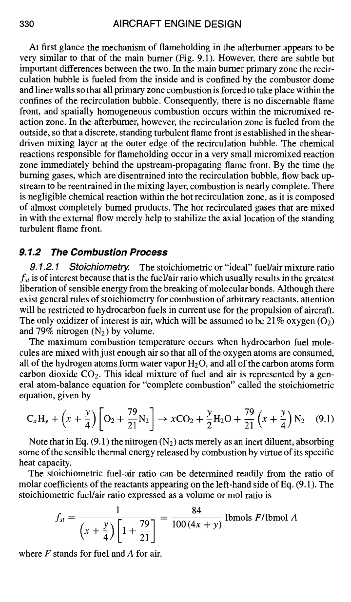
9.1.2 The Combustion Process
9.1.2.1 Stoichiometry.
The stoichiometric or "ideal" fuel/air mixture ratio
fst
is of interest because that is the fuel/air ratio which usually results in the greatest
liberation of sensible energy from the breaking of molecular bonds. Although there
exist general rules of stoichiometry for combustion of arbitrary reactants, attention
will be restricted to hydrocarbon fuels in current use for the propulsion of aircraft.
The only oxidizer of interest is air, which will be assumed to be 21% oxygen (02)
and 79% nitrogen (N2) by volume.
The maximum combustion temperature occurs when hydrocarbon fuel mole-
cules are mixed with just enough air so that all of the oxygen atoms are consumed,
all of the hydrogen atoms form water vapor H20, and all of the carbon atoms form
carbon dioxide CO2. This ideal mixture of fuel and air is represented by a gen-
eral atom-balance equation for "complete combustion" called the stoichiometric
equation, given by
[ 79N] 79(x Y
CxHy]-(xq4)
O2"~ "
2J ''+XCO2"~-yH20"~-2 ~-~ +~)N2 (9.1)
Note that in Eq. (9.1) the nitrogen (N2) acts merely as an inert diluent, absorbing
some of the sensible thermal energy released by combustion by virtue of its specific
heat capacity.
The stoichiometric fuel-air ratio can be determined readily from the ratio of
molar coefficients of the reactants appearing on the left-hand side of Eq. (9.1). The
stoichiometric fuel/air ratio expressed as a volume or mol ratio is
1 84
f"= (x+~)Y [l+~i-
791-- lO0(4x+y) lbm°lsF/lbm°lA
where F stands for fuel and A for air.
DESIGN: COMBUSTION SYSTEMS 331
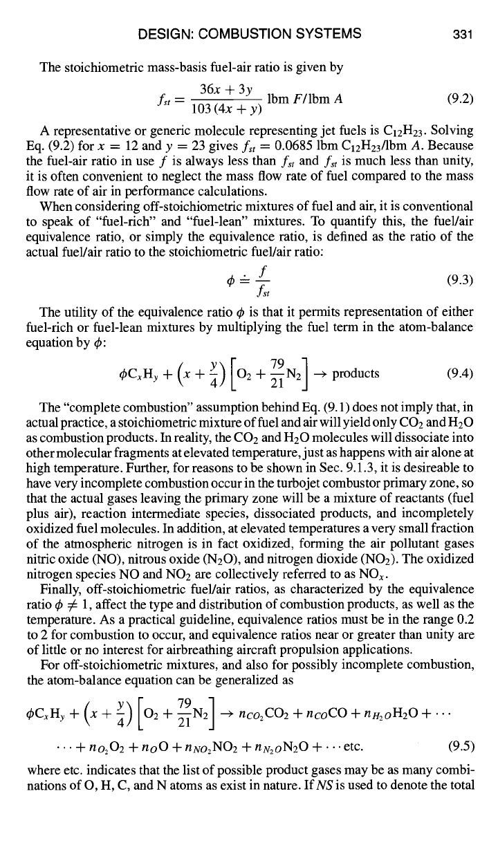
The stoichiometric mass-basis fuel-air ratio is given by
36x + 3y
fst --
Ibm F/Ibm A (9.2)
103 (4x + y)
A representative or generic molecule representing jet fuels is C12H23. Solving
Eq. (9.2) for x = 12 and y = 23 gives fst = 0.0685 Ibm C12H23/lbm A. Because
the fuel-air ratio in use f is always less than
fst
and
fst
is much less than unity,
it is often convenient to neglect the mass flow rate of fuel compared to the mass
flow rate of air in performance calculations.
When considering off-stoichiometric mixtures of fuel and air, it is conventional
to speak of "fuel-rich" and "fuel-lean" mixtures. To quantify this, the fuel/air
equivalence ratio, or simply the equivalence ratio, is defined as the ratio of the
actual fuel/air ratio to the stoichiometric fuel/air ratio:
4~'= -- f (9.3)
f,t
The utility of the equivalence ratio ~b is that it permits representation of either
fuel-rich or fuel-lean mixtures by multiplying the fuel term in the atom-balance
equation by ~b:
( y)[ 79 ]
epCxHy + x + -~
O2 + ~i-N2 ~ products (9.4)
The "complete combustion" assumption behind Eq. (9.1) does not imply that, in
actual practice, a stoichiometric mixture of fuel and air will yield only COz and HzO
as combustion products. In reality, the CO2 and H20 molecules will dissociate into
other molecular fragments at elevated temperature, just as happens with air alone at
high temperature. Further, for reasons to be shown in Sec. 9.1.3, it is desireable to
have very incomplete combustion occur in the turbojet combustor primary zone, so
that the actual gases leaving the primary zone will be a mixture of reactants (fuel
plus air), reaction intermediate species, dissociated products, and incompletely
oxidized fuel molecules. In addition, at elevated temperatures a very small fraction
of the atmospheric nitrogen is in fact oxidized, forming the air pollutant gases
nitric oxide (NO), nitrous oxide (N20), and nitrogen dioxide (NO2). The oxidized
nitrogen species NO and
NO2 are
collectively referred to as NOx.
Finally, off-stoichiometric fuel/air ratios, as characterized by the equivalence
ratio 4~ 5 ~ 1, affect the type and distribution of combustion products, as well as the
temperature. As a practical guideline, equivalence ratios must be in the range 0.2
to 2 for combustion to occur, and equivalence ratios near or greater than unity are
of little or no interest for airbreathing aircraft propulsion applications.
For off-stoichiometric mixtures, and also for possibly incomplete combustion,
the atom-balance equation can be generalized as
79 N ]
~gfxHy--~-(x--~- Y)
O2-q- ~-- i-
2j ---+ nco2fO2-~-ncofO-~-l'lH20n20--[-...
• .. + no202 +
noO q- nNOzNO2 -k- nN2oN20 + ""
etc. (9.5)
where etc. indicates that the list of possible product gases may be as many combi-
nations of O, H, C, and N atoms as exist in nature.
IfNS
is used to denote the total
332 AIRCRAFT ENGINE DESIGN
number of product species that may appear on the right-hand side of Eq. (9.5), the
messy right-hand side of Eq. (9.5) can be represented with the notation
79 N
q
NS
fbfxny
Jr"
(\x + Y]..~. 02 + ~-~
2J -->
~_niAi
(9.6)
i=1
where
A i
represents the chemical formula of the ith gas molecule appearing
in the
NS
product gases. Methods for finding the actual composition of the
post-combustion product gases, as represented by the set of mole numbers
{ni
}
in
Eq. (9.6), by assuming either chemical equilibrium or finite-rate chemistry (chem-
ical kinetics), are provided in the AEDsys software programs EQL and KINETX,
respectively.
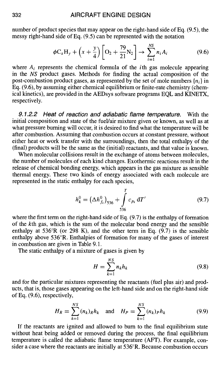
9.1.2.2 Heat of reaction and adiabatic flame temperature.
With the
initial composition and state of the fuel/air mixture given or known, as well as at
what pressure burning will occur, it is desired to find what the temperature will be
after combustion. Assuming that combustion occurs at constant pressure, without
either heat or work transfer with the surroundings, then the total enthalpy of the
(final) products will be the same as the (initial) reactants, and that value is known.
When molecular collisions result in the exchange of atoms between molecules,
the number of molecules of each kind changes. Exothermic reactions result in the
release of chemical bonding energy, which appears in the gas mixture as sensible
thermal energy. These two kinds of energy associated with each molecule are
represented in the static enthalpy for each species,
T
= (Ah~k)536 -+- j
Cp,~
dT'
(9.7)
h 0
536
where the first term on the right-hand side of Eq. (9.7) is the enthalpy of formation
of the kth gas, which is the sum of the molecular bond energy and the sensible
enthalpy at 536°R (or 298 K), and the other term in Eq. (9.7) is the sensible
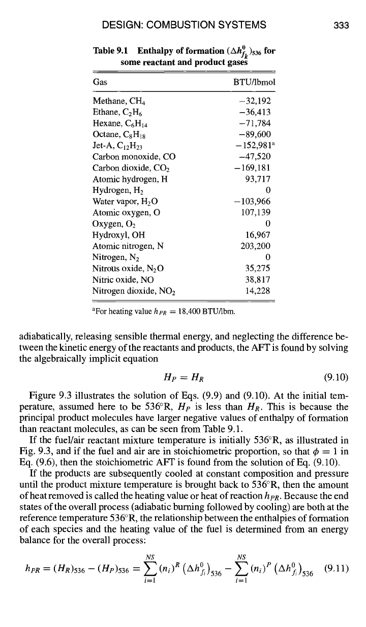
enthalpy above 536°R. Enthalpies of formation for many of the gases of interest
in combustion are given in Table 9.1.
The static enthalpy of a mixture of gases is given by
NS
= ~_~ nkh~
(9.8) H
k=l
and for the particular mixtures representing the reactants (fuel plus air) and prod-
ucts, that is, those gases appearing on the left-hand side and on the right-hand side
of Eq. (9.6), respectively,
NS NS
HR = Z(nk)lchk
and Hp = Z(nk)ph~
(9.9)
k=l k=l
If the reactants are ignited and allowed to burn to the final equilibrium state
without heat being added or removed during the process, the final equilibrium
temperature is called the adiabatic flame temperature (AFT). For example, con-
sider a case where the reactants are initially at 536°R. Because combustion occurs
DESIGN: COMBUSTION SYSTEMS
333
Table 9.1 Enthalpy
of formation
(Ah~k)536 for
some reactant and product gases
Gas BTUllbmol
Methane, CH4 -
32,192
Ethane, C2H6
-36,413
Hexane, C6H14
-71,784
Octane, C8H18 -89,600
Jet-A, ClzH23 - 152,981 ~
Carbon monoxide, CO -47,520
Carbon dioxide, CO2 - 169,181
Atomic hydrogen, H 93,717
Hydrogen, H2 0
Water vapor, H20 - 103,966
Atomic oxygen, O 10%139
Oxygen, 02 0
Hydroxyl, OH 16,967
Atomic nitrogen, N 203,200
Nitrogen, N2 0
Nitrous oxide, N20 35,275
Nitric oxide, NO 38,817
Nitrogen dioxide, NO2 14,228
aFor heating value h pR = 18,400 BTU/lbrn.
adiabatically, releasing sensible thermal energy, and neglecting the difference be-
tween the kinetic energy of the reactants and products, the AFT is found by solving
the algebraically implicit equation
lip = HR
(9.10)
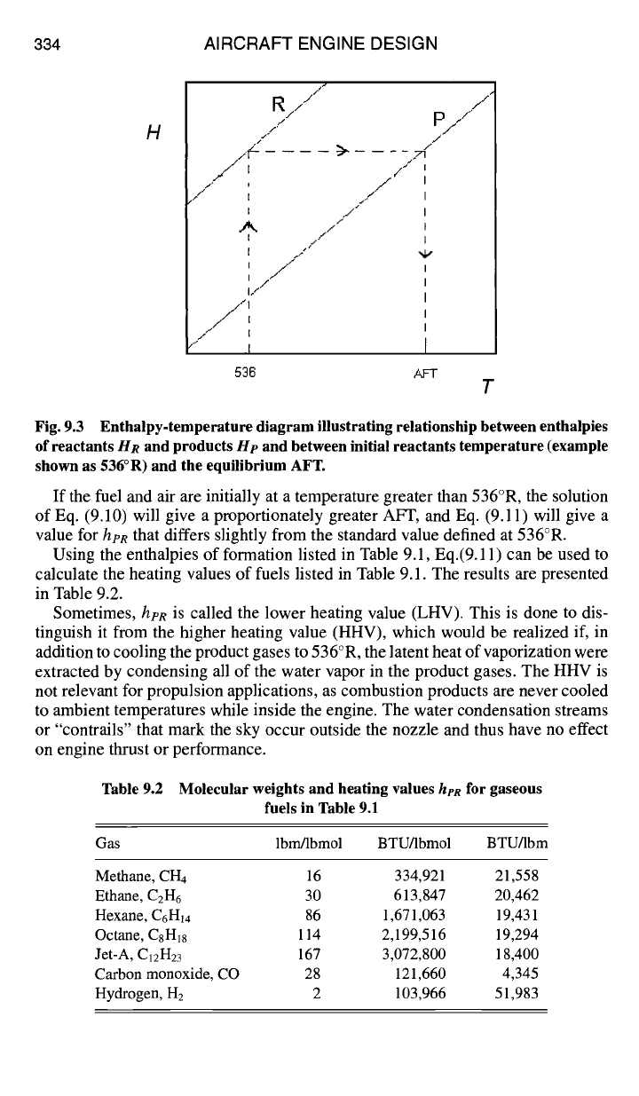
Figure 9.3 illustrates the solution of Eqs. (9.9) and (9.10). At the initial tem-
perature, assumed here to be 536°R,
Hp
is less than HR. This is because the
principal product molecules have larger negative values of enthalpy of formation
than reactant molecules, as can be seen from Table 9.1.
If the fuel/air reactant mixture temperature is initially 536°R, as illustrated in
Fig. 9.3, and if the fuel and air are in stoichiometric proportion, so that ~b = 1 in
Eq. (9.6), then the stoichiometric AFT is found from the solution of Eq. (9.10).
If the products are subsequently cooled at constant composition and pressure
until the product mixture temperature is brought back to 536°R, then the amount
of heat removed is called the heating value or heat of reaction hpR. Because the end
states of the overall process (adiabatic burning followed by cooling) are both at the
reference temperature 536°R, the relationship between the enthalpies of formation
of each species and the heating value of the fuel is determined from an energy
balance for the overall process:
NS NS
hpR = (HR)536 --(Hp)536 = ~ (ni) R (Ah~i)536 - ~ (hi) P
(Ah~i)536 (9.11)
i=1 i=1
334
AIRCRAFT ENGINE DESIGN
H
R////"
/
F.
#, )
/" i
i
A
I
j
#
J
> - _ _
-<
f
.,/
t"
/,,-"
.,,/
I /I "4,"
I ,,//
I
i/"~
///"11
:F" I
.I
536 AFT
T
Fig. 9.3 Enthalpy-temperature diagram illustrating relationship between enthalpies
of reactants
HR
and products He and between initial reactants temperature (example
shown as 536°R) and the equilibrium AFT.
If the fuel and air are initially at a temperature greater than 536°R, the solution
of Eq. (9.10) will give a proportionately greater AFT, and Eq. (9.11) will give a
value for her that differs slightly from the standard value defined at 536°R.
Using the enthalpies of formation listed in Table 9.1, Eq.(9.11) can be used to
calculate the heating values of fuels listed in Table 9.1. The results are presented
in Table 9.2.
Sometimes,
h?R
is called the lower heating value (LHV). This is done to dis-
tinguish it from the higher heating value (HHV), which would be realized if, in
addition to cooling the product gases to 536°R, the latent heat of vaporization were
extracted by condensing all of the water vapor in the product gases. The HHV is
not relevant for propulsion applications, as combustion products are never cooled
to ambient temperatures while inside the engine. The water condensation streams
or "contrails" that mark the sky occur outside the nozzle and thus have no effect
on engine thrust or performance.
Table 9.2 Molecular weights and heating values
her
for gaseous
fuels in Table 9.1
Gas lbrn/lbmol BTU/lbmol BTU/lbm
Methane, CH4 16 334,921 21,558
Ethane, C2H6 30 613,847 20,462
Hexane, C6H14 86 1,671,063 19,431
Octane, C8H18 114 2,199,516 19,294
Jet-A, C12H23 167 3,072,800 18,400
Carbon monoxide, CO 28 121,660 4,345
Hydrogen, H2 2 103,966 51,983
DESIGN: COMBUSTION SYSTEMS 335
The AEDsys program EQL finds the equilibrium AFT for the fuels listed in
Table 9.2.
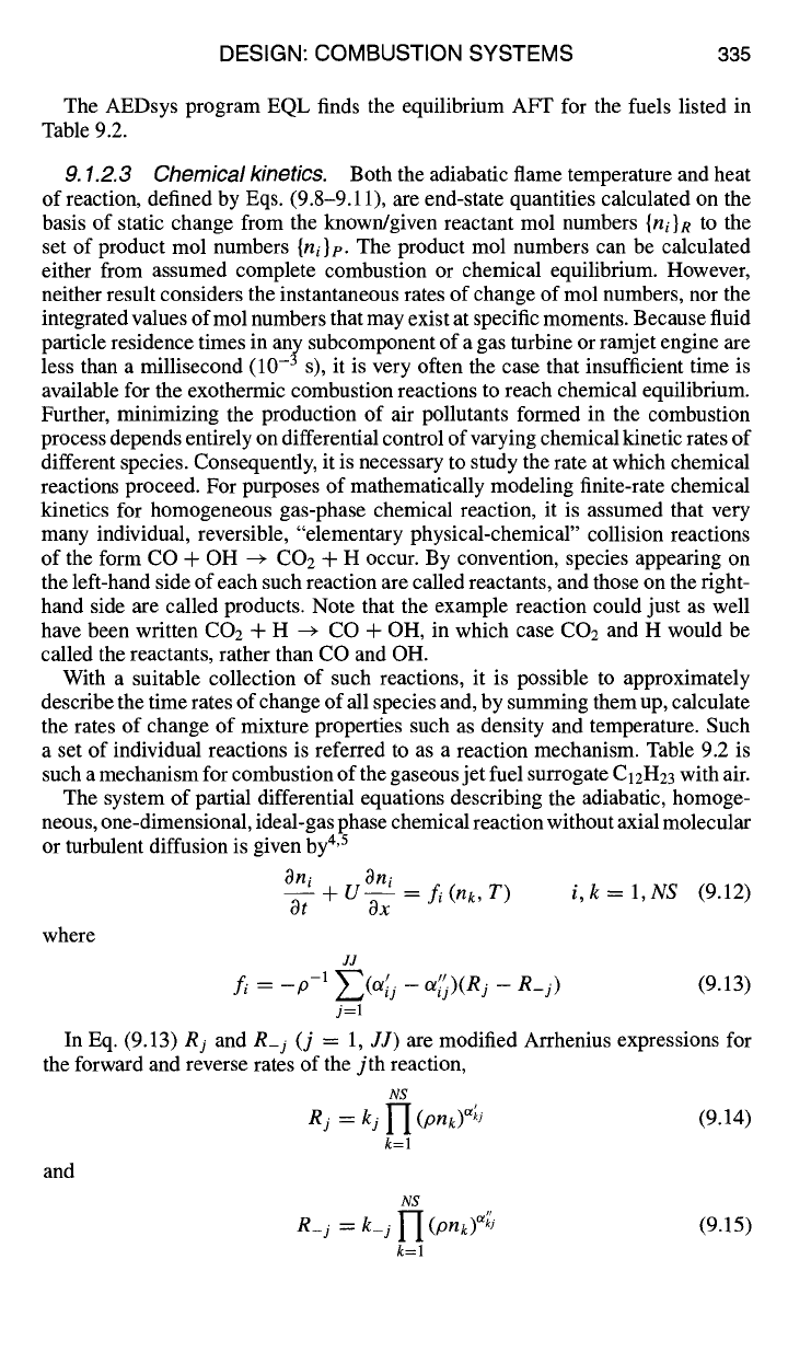
9.1.2.3 Chemical kinetics. Both the adiabatic flame temperature and heat
of reaction, defined by Eqs. (9.8-9.11), are end-state quantities calculated on the
basis of static change from the known/given reactant mol numbers
{ni}R
to the
set of product mol numbers
{ni}p.
The product mol numbers can be calculated
either from assumed complete combustion or chemical equilibrium. However,
neither result considers the instantaneous rates of change of mol numbers, nor the
integrated values ofmol numbers that may exist at specific moments. Because fluid
particle residence times in any subcomponent of a gas turbine or ramjet engine are
less than a millisecond (10 -3 s), it is very often the case that insufficient time is
available for the exothermic combustion reactions to reach chemical equilibrium.
Further, minimizing the production of air pollutants formed in the combustion
process depends entirely on differential control of varying chemical kinetic rates of
different species. Consequently, it is necessary to study the rate at which chemical
reactions proceed. For purposes of mathematically modeling finite-rate chemical
kinetics for homogeneous gas-phase chemical reaction, it is assumed that very
many individual, reversible, "elementary physical-chemical" collision reactions
of the form CO + OH -* CO: + H occur. By convention, species appearing on
the left-hand side of each such reaction are called reactants, and those on the right-
hand side are called products. Note that the example reaction could just as well
have been written CO: + H --~ CO + OH, in which case CO2 and H would be
called the reactants, rather than CO and OH.
With a suitable collection of such reactions, it is possible to approximately
describe the time rates of change of all species and, by summing them up, calculate
the rates of change of mixture properties such as density and temperature. Such
a set of individual reactions is referred to as a reaction mechanism. Table 9.2 is
such a mechanism for combustion of the gaseous jet fuel surrogate
C12H23
with air.
The system of partial differential equations describing the adiabatic, homoge-
neous, one-dimensional, ideal-gas phase chemical reaction without axial molecular
or turbulent diffusion is given by 4'5
Oni Oni
O--f +U-~x = fi(nk, T) i,k= l,NS
(9.12)
where
JJ
fi = _p-1 ~-'~(Ol~j -- Ol~)(Rj -- R_j)
(9.13)
j=l
In Eq. (9.13) Rj and R_j (j = 1,
JJ) are
modified Arrhenius expressions for
the forward and reverse rates of the jth reaction,
NS
Rj = kj I-I (pnk)u'k2
(9.14)
k=l
and
NS
R_j = k_j 1-I (Pnk)%
k=l
(9.15)