Mattingly J.D., Heiser W.H., Pratt D.T. Aircraft Engine Design
Подождите немного. Документ загружается.

296 AIRCRAFT ENGINE DESIGN
0
1.0
0.9
0.8
0.7
0.6
0.5
0.4
0.3
0.2
r
r~
I
I
I I
I
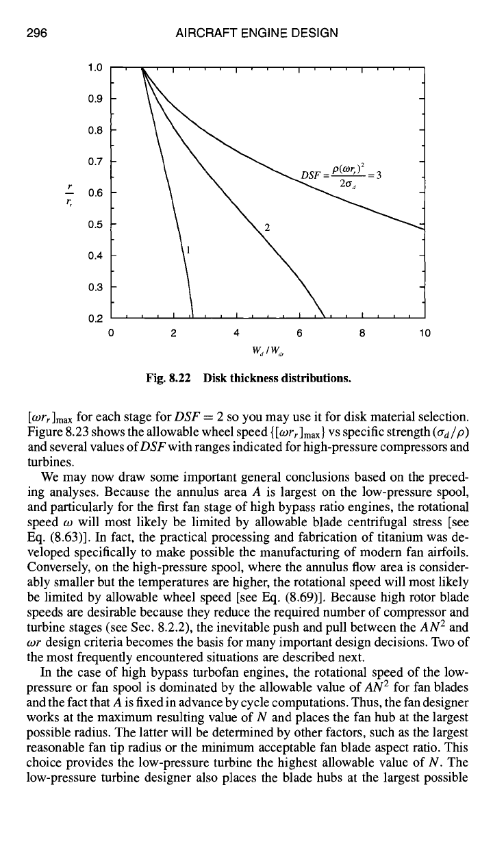
~ DSF = P(°)r~)2
=3
t,, ,
2 4 6 8
%/%r
Fig. 8.22 Disk thickness distributions.
10
[O)rr]max
for each stage for
DSF
= 2 so you may use it for disk material selection.
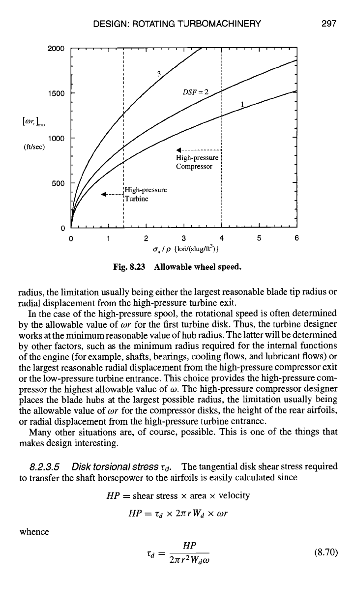
Figure 8.23 shows the allowable wheel speed
{[Wrr]max}
VS specific strength
(ad/P)
and several values
of DSF
with ranges indicated for high-pressure compressors and
turbines.
We may now draw some important general conclusions based on the preced-
ing analyses. Because the annulus area A is largest on the low-pressure spool,
and particularly for the first fan stage of high bypass ratio engines, the rotational
speed w will most likely be limited by allowable blade centrifugal stress [see
Eq. (8.63)]. In fact, the practical processing and fabrication of titanium was de-
veloped specifically to make possible the manufacturing of modem fan airfoils.
Conversely, on the high-pressure spool, where the annulus flow area is consider-
ably smaller but the temperatures are higher, the rotational speed will most likely
be limited by allowable wheel speed [see Eq. (8.69)]. Because high rotor blade
speeds are desirable because they reduce the required number of compressor and
turbine stages (see Sec. 8.2.2), the inevitable push and pull between the
AN 2
and
wr design criteria becomes the basis for many important design decisions. Two of
the most frequently encountered situations are described next.
In the case of high bypass turbofan engines, the rotational speed of the low-
pressure or fan spool is dominated by the allowable value of
AN 2
for fan blades
and the fact that A is fixed in advance by cycle computations. Thus, the fan designer
works at the maximum resulting value of N and places the fan hub at the largest
possible radius. The latter will be determined by other factors, such as the largest
reasonable fan tip radius or the minimum acceptable fan blade aspect ratio. This
choice provides the low-pressure turbine the highest allowable value of N. The
low-pressure turbine designer also places the blade hubs at the largest possible
DESIGN: ROTATING TURBOMACHINERY 297
[o)r ]m.x
(ft/sec)
2000
1500
1000
500
/// G:;;;==e
/// Compress or
~/// ~1- ..... H~h;pressure
, , , , I i i i I t i i i I i i i i i i , , I , , , ,
0 1 2 3 4 5 6
O" d / p {ksi/(slug/ft3)}
Fig. 8.23 Allowable wheel speed.
radius, the limitation usually being either the largest reasonable blade tip radius or
radial displacement from the high-pressure turbine exit.
In the case of the high-pressure spool, the rotational speed is often determined
by the allowable value of wr for the first turbine disk. Thus, the turbine designer
works at the minimum reasonable value of hub radius. The latter will be determined
by other factors, such as the minimum radius required for the internal functions
of the engine (for example, shafts, bearings, cooling flows, and lubricant flows) or
the largest reasonable radial displacement from the high-pressure compressor exit
or the low-pressure turbine entrance. This choice provides the high-pressure com-
pressor the highest allowable value of w. The high-pressure compressor designer
places the blade hubs at the largest possible radius, the limitation usually being
the allowable value of o~r for the compressor disks, the height of the rear airfoils,
or radial displacement from the high-pressure turbine entrance.
Many other situations are, of course, possible. This is one of the things that
makes design interesting.
8.2.3.5
to transfer the shaft horsepower to the airfoils is easily calculated since
HP
= shear stress x area x velocity
HP = rd X 2rcrWd x cor
whence
Disk torsional stress "~d.
The tangential disk shear stress required
HP
(8.70)
rd- 27rrZWdc °
298 AIRCRAFT ENGINE DESIGN
For example, by choosing the following typical values of disk properties
HP = 10,000 hp
r = 0.30 ft
Wa = 0.10 ft
w = 1000 rad/s
then Eq. (8.70) shows that ra = 675 psi, which makes a relatively small contribu-
tion to the overall stress.
8.2.3.6 Disk thermal differential stress cr t.
Itwasnotedearlierthatdiffer-
ential thermal stresses are often more important than one might think. Although it
is difficult to provide the type of complex analysis required for LCF life estimation,
the following classical example makes the point clearly enough.
Considering a circular disk of constant thickness with no center hole and a
temperature distribution that depends only on radius [T = T(r)], it can be shown
TM
that the radial tensile stress is
{lforh
1 f0r }
~tr =
orE .--5 Tr dr - ~ Tr dr (8.71)
r h
where ot is the coefficient of linear thermal expansion and E is the modulus of
elasticity, and the tangential tensile stress is
{ 1 f0rh-- 1 f0r }
ato = orE r~ Tr dr + -~ Tr dr - T (8.72)
both of which are zero if the temperature is constant. An interesting illustrative
case is that of the linear temperature distribution T = To -t- AT(r/rh), for which
Eq. (8.71) becomes
Crtr- ~ 1 - (8.73)
and Eq. (8.72) becomes
e'xT" (1_ 2 r )
rrto -- ~ -~h (8.74)
both of which have a maximum magnitude of a E A T/3 at r = 0. For example, by
choosing typical values of
ot = 1 x 10 -5 1/°F
E = 20 x 106 psi
AT = 100°F
then Eqs. (8.73) and (8.74) show that the maximum magnitude of crt,. and ato is
6700 psi! This simple case demonstrates forcefully that thermal stresses can be
DESIGN: ROTATING TURBOMACHINERY 299
Table 8.9 Airfoil aspect ratio
Component Axial aspect ratio
Fan 3-6
Compressor 1-5
High-pressure turbine 1-3
Low-pressure turbine 2-4
very large and, therefore, must be carefully accounted for and reduced as much as
possible. This is especially true during transient operation.
With this perspective, it is possible to imagine that truly enormous stresses
could be generated in the thin outer walls of the cooled turbine airfoils, if they
are not very carefully designed. Because such stresses will be proportional to the
temperature difference between the mainstream and the cooling air, there is also
a limit to how cold a coolant may be used before it no longer truly "protects" the
material. Furthermore, the frequently cited materials limitations on Tt3
or
Zt4 are
often caused by the transient tangential thermal differential stresses that arise at
the hot rims of the high-pressure compressor and turbine disks when the throttle
is retarded and the temperature of the adjacent airflow is suddenly reduced.
8.2.3. 7 Airfoil aspect ratio. At some point in the analysis, it becomes im-
portant to be able to estimate hr and Wr (see Fig. 8.17), both of which approximate
the axial chord at the hub of the rotating airfoil. Because the latter results from
much more elaborate calculations, a rule of thumb based on many successful de-
signs is used in COMPR and TURBN for preliminary calculations. The rule of
thumb is that the "axial aspect ratio" of the rotating airfoils [that is, height to hub
axial chord
or
(rt - rh)/hr]
depends largely on the component under consideration,
as shown in Table 8.9.
8.3 Example AAF Engine Component Design: Rotating Turboma-
chinery
We will now design the rotating components for the AAF Engine (see Sec. 6.5).
This example will illustrate the preliminary design of the axial flow fan, high-
pressure compressor (HPC), high-pressure turbine (HPT), and low-pressure turbine
(LPT). The designs will be based on the methods of Sec. 8.2. The design point and
off-design component performance data, which provide the starting point for the
designs, were assembled before in the following figures and tables: Fig. 7.1 AAF
Engine design point performance data; Table 7.El AAF Engine design point
interface quantities; Fig. 7.E1 Fan performance fan pressure ratio; Fig. 7.E2 HPC
performance--HP compressor pressure ratio; Fig. 7.E3 Low-pressure turbine
performance--pressure ratio; Table 7.E3 AAF Engine turbomachinery perfor-
mance at 00 = OObreak, sea level, standard day (M0 = 0.612); Fig. 7.El0 AAF En-
gine fan operating line; Fig. 7.El I AAF Engine high-pressure compressor operat-
ing line; and Fig. 7.E9 AAF Engine high- and low-pressure turbine operating lines.
300 AIRCRAFT ENGINE DESIGN
Further supportive data to be used in the selection of materials for the various
component parts are contained in Table 8.5 and Figs. 8.16 and 8.17. As already
noted, it is initially assumed that the AAF is twin-engined and that it will be
powered by two AAF Engines having the general configuration shown in Fig. 4.1a.
Following the preceding reasoning, it is presumed that the maximum mechanical
speeds of the low- and high-pressure spools are determined by the structurally ac-
ceptable mechanical speeds for the fan and the high-pressure turbine, respectively.
Consequently, the design of these two components is considered first followed by
the high-pressure compressor and the low-pressure turbine in that order. These
presumptions are, of course, subject to later examination and, if necessary, recon-
sideration.
8.3.1
Fan DesignmAAF Engine
The process begins with the selection of the fan design point and the determi-
nation of the number of fan stages. Design choices are then made for the stage
parameters D, M0, tr, and ec and the aerodynamic definition of each stage fixed.
Next, rotating airfoil material and taper ratio choices are selected; the rotational
speed of the low-speed spool is found from centrifugal stress considerations; and
the airfoil radii are calculated. Finally, the wheel material is selected; the wheel
parameters
hr and
~btades/~r are
estimated; and the wheel speed, disk shape factor,
and rim web thickness are determined by rim and disk stresses considerations.
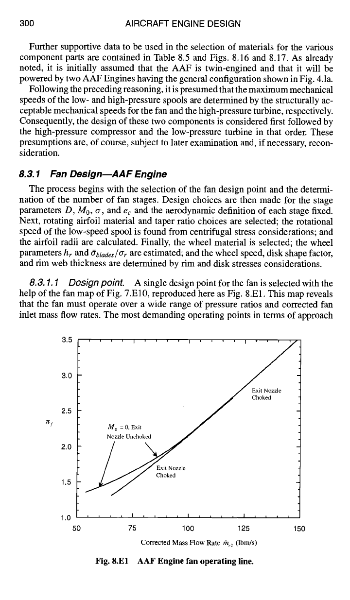
8.3.1.1 Design point. A single design point for the fan is selected with the
help of the fan map of Fig. 7.El0, reproduced here as Fig. 8.El. This map reveals
that the fan must operate over a wide range of pressure ratios and corrected fan
inlet mass flow rates. The most demanding operating points in terms of approach
~j
3.5
3.0
2.5
2.0
1.5
' ' ' ' I ' ' ' ' I ' ' ' ' I ' ' ' '
M o = 0, Exit / Chokej d
Nozzle Uncho~
JJ Exit Nozzle
~~ Choked
1.0 , , , , I , , , , I , , , , I ,
50 75 100 125
Corrected Mass Flow Rate th 2 (Ibm/s)
Fig. 8.El AAF Engine fan operating line.
I I I
150
DESIGN: ROTATING TURBOMACHINERY 301
Station m dot gamma Pt Tt
(ibm/s) (psia) (R)
0 176.95 1.4000 18.923 557.54
1 176.95 1.4000 18.923 557.54
2 176.95 1.4000 18.166 557.54
13 176.95 1.4000 63.607 833.26
bypass 76.01 1.4000 63.507 833.26
2.5 100.94 1.4000 63.507 833.26
3 100.94 1.4000 509.015 1613.34
3.1 89.84 1.4000 509.015 1613.34
3.2 89.84 1.4000 503.925 1613.34
MB fuel 2.5064
4 92.34 1.3000 483.564 3199.99
4.1 97.39 1.3000 3101.86
4.4 97.39 1.3000 2435.95
4.5 102.44 1.3000 149.089 2380.29
5 102.44 1.3000 63.078 1990.88
6 102.44 1.3000 63.078 1990.88
16 76.01 1.4000 63.507 833.26
6A 178.45 1.3360 60.769 1554.97
AB fuel 6.6782
7 185.13 1.3000 57.731 3600.00
8 185.13 1.3000 57.731 3600.00
9 185.13 1.3000 55.999 3600.00
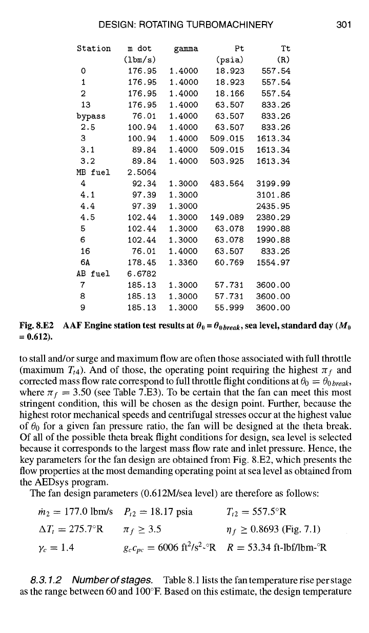
Fig. 8.E2 AAF Engine station test results at
Oo = Oobreak,
sea level, standard day (Mo
= 0.612).
to stall and/or surge and maximum flow are often those associated with full throttle
(maximum Tt4). And of those, the operating point requiring the highest 7gf and
corrected mass flow rate correspond to full throttle flight conditions at 00 =
OObreak,
where Trf ~-- 3.50 (see Table 7.E3). To be certain that the fan can meet this most
stringent condition, this will be chosen as the design point. Further, because the
highest rotor mechanical speeds and centrifugal stresses occur at the highest value
of 00 for a given fan pressure ratio, the fan will be designed at the theta break.
Of all of the possible theta break flight conditions for design, sea level is selected
because it corresponds to the largest mass flow rate and inlet pressure. Hence, the
key parameters for the fan design are obtained from Fig. 8.E2, which presents the
flow properties at the most demanding operating point at sea level as obtained from
the AEDsys program.
The fan design parameters (0.612M/sea level) are therefore as follows:
#/2 = 177.0 lbm/s
Pt2
- 18.17 psia
Tt2
= 557.5°R
ATt
= 275.7°R ~f >_ 3.5 ~f _> 0.8693 (Fig. 7.1)
Yc = 1.4 gcCpc
= 6006 ftZ/sZ-°R R = 53.34 ft-lbf/lbm-°R
8.3. 1.2 Number of stages.
Table 8.1 lists the fan temperature rise per stage
as the range between 60 and 100°F. Based on this estimate, the design temperature
302 AIRCRAFT ENGINE DESIGN
rise of 275.7°F for the fan will require either three or four stages. The change in total
temperature for each stage is constant for the repeating stage, repeating row, mean-
line design [see. Eq. (8.11)]. Assuming three stages, a total temperature increase
of 91.9°F is required in each stage, and the required first stage total pressure ratio
obtained from Eq. (4.9a-CPG) is
×,.e~ (557.5 + 91.9) 3"5×°'89
:rs = (rs) ×,-1 \ 557.5 J = (1.1648) 3115 1.6083
If we assume a stage inlet Mach number M1 = 0.6, a diffusion factor D = 0.5,
a solidity a ---- 1.0, and a polytropic efficiency
ef =
0.9,
Fig. 8.2a shows that an
excessively large inlet flow angle oq > 70 deg is required. To obtain the required
stage temperature rise and keep the size of inlet flow angle al reasonable, increases
will be needed in the diffusion factor D, the solidity a, and/or inlet stage Mach
number MI.
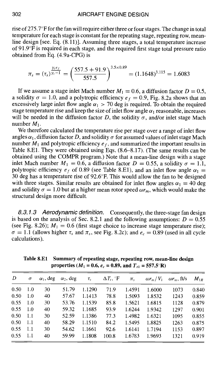
We therefore calculated the temperature rise per stage over a range of inlet flow
angles al, diffusion factor D, and solidity a for assumed values of inlet stage Mach
number M1 and polytropic efficiency
ef,
and summarized the important results in
Table 8.El. They were obtained using Eqs. (8.6-8.17). (The same results can be
obtained using the COMPR program.) Note that a mean-line design with a stage
inlet Mach number Ml = 0.6, a diffusion factor D = 0.55, a solidity a = 1.1,
polytropic efficiency ef of 0.89 (see Table 8.El), and an inlet flow angle oq =
30 deg has a temperature rise of 92.6°E This would allow the fan to be designed
with three stages. Similar results are obtained for inlet flow angles oq = 40 deg
and solidity a = 1.0 but at a higher mean rotor speed
COrm,
which would make the
structural design more difficult.
8.3. 1.3 Aerodynamic definition.
Consequently, the three-stage fan design
is based on the analysis of Sec. 8.2.1 and the following assumptions: D = 0.55
(see Fig. 8.26); M~ ---- 0.6 (first stage choice to increase stage temperature rise);
a = 1.1 (allows higher rs and zrs, see Fig. 8.2c); and
ec
---- 0.89 (used in all cycle
calculations).
Table 8.El Summary of repeating stage, repeating row, mean-line design
properties (M1 = 0.6,
ec =
0.89, and
Tt~ =
557.5C>R)
D a Ofl, deg a2, deg r, AT,, °F zr,
COrm/Vi COrm,
ft/s
M)R
0.50 1.0 30 51.79 1.1290 71.9 1.4591 1.6000 1073 0.840
0.50 1.0 40 57.67 1.1413 78.8 1.5093 1.8532 1243 0.859
0.55 1.0 30 53.76 1.1539 85.8 1.5621 1.6815 1128 0.879
0.55 1.0 40 59.32 1.1685 93.9 1.6244 1.9342 1297 0.901
0.50 1.1 30 52.59 1.1386 77.3 1.4982 1.6321 1095 0.855
0.50 1.1 40 58.29 1.1510 84.2 1.5495 1.8825 1263 0.875
0.55 1.1 30 54.62 1.1661 92.6 1.6141 1.7194 1153 0.897
0.55 1.1 40 59.99 1.1808 100.8 1.6783 1.9693 1321 0.919
DESIGN:
ROTATING TURBOMACHINERY 303
The required stage total temperature rise of 91.9°F can be obtained with an inlet
flow angle 0/1 = 29.2 deg with the following results:
0/1 = 29.20 assumed
F = 2.666 Eq. (8.7)
0/2 = 54.20 Eq. (8.6)
A0/= 25.00 0/2
--
0/1
rs = 1.153 Eq. (8.12)
ATt
= 91.90°F
Ttl(vs -
1)
7r~ = 1.165 Eq. (8.13)
so that
TW Ts,d
V1 = Mlal = Mlastd 1 + ()'c --
1)M2/2
o)r m
= 1.698
vl
COrm
= 1139 ft/s
MIR = 0.895
= 670.7 ft/s
Eq. (8.16)
Eq. (8.17)
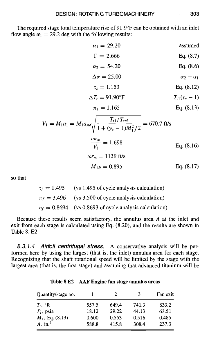
Quantity/stage no. 1 2 3 Fan exit
Tt, °R 557.5 649.4 741.3 833.2
Pt, psia 18.12 29.22 44.13 63.51
M1, Eq. (8.13) 0.600 0.553 0.516 0.485
A, in. 2 588.8 415.8 308.4 237.3
Table 8.E2 AAF Engine fan stage annulus areas
8.3.1.4 Airfoil centrifugal stress.
A conservative analysis will be per-
formed here by using the largest (that is, the inlet) annulus area for each stage.
Recognizing that the shaft rotational speed will be limited by the stage with the
largest area (that is, the first stage) and assuming that advanced titanium will be
rf = 1.495 (vs 1.495 of cycle analysis calculation)
:rf = 3.496 (vs 3.500 of cycle analysis calculation)
0f = 0.8694 (vs 0.8693 of cycle analysis calculation)
Because these results seem satisfactory, the annulus area A at the inlet and
exit from each stage is calculated using Eq. (8.20), and the results are shown in
Table 8. E2.
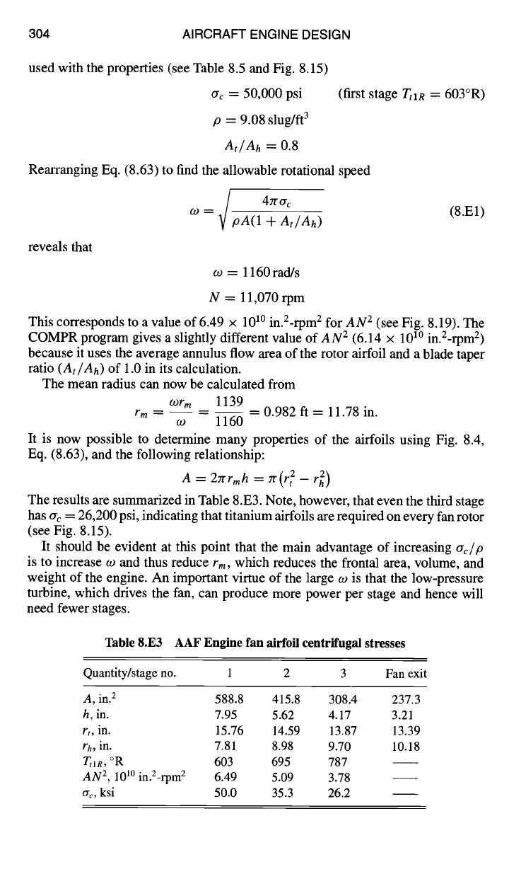
304 AIRCRAFT ENGINE DESIGN
used with the properties (see Table 8.5 and Fig. 8.15)
ac = 50,000 psi
p ---- 9.08 slug/ft 3
At/Ah
-=- 0.8
Rearranging Eq. (8.63) to find the allowable rotational speed
4zr ac
w = pA(1 -I-
At/Ah)
reveals that
(first stage
Ttl R ~--
603°R)
(8.El)
o) : 1160 rad/s
N = 11,070 rpm
This corresponds to a value of 6.49 × 101° in.2-rpm 2 for
AN 2
(see Fig. 8.19). The
COMPR program gives a slightly different value of
AN 2
(6.14 × 101° in.Z-rpm 2)
because it uses the average annulus flow area of the rotor airfoil and a blade taper
ratio
(At/Ah)
of 1.0 in its calculation.
The mean radius can now be calculated from
wrm
1139
rm ....
0.982 ft = 11.78 in.
co 1160
It is now possible to determine many properties of the airfoils using Fig. 8.4,
Eq. (8.63), and the following relationship:
A = 2Zrrmh = zr(r 2 - r 2)
The results are summarized in Table 8.E3. Note, however, that even the third stage
has ac = 26,200 psi, indicating that titanium airfoils are required on every fan rotor
(see Fig. 8.15).
It should be evident at this point that the main advantage of increasing
~rc/p
is to increase w and thus reduce
rm,
which reduces the frontal area, volume, and
weight of the engine. An important virtue of the large o~ is that the low-pressure
turbine, which drives the fan, can produce more power per stage and hence will
need fewer stages.
Table 8.E3 AAF Engine fan airfoil centrifugal stresses
Quantity/stage no. 1 2 3 Fan exit
A, in. 2 588.8 415.8 308.4 237.3
h, in. 7.95 5.62 4.17 3.21
r,, in. 15.76 14.59 13.87 13.39
rh, in. 7.81 8.98 9.70 10.18
TtlR, °R 603 695 787
AN 2,
10 l° in.Z-rpm 2 6.49 5.09 3.78
crc, ksi 50.0 35.3 26.2
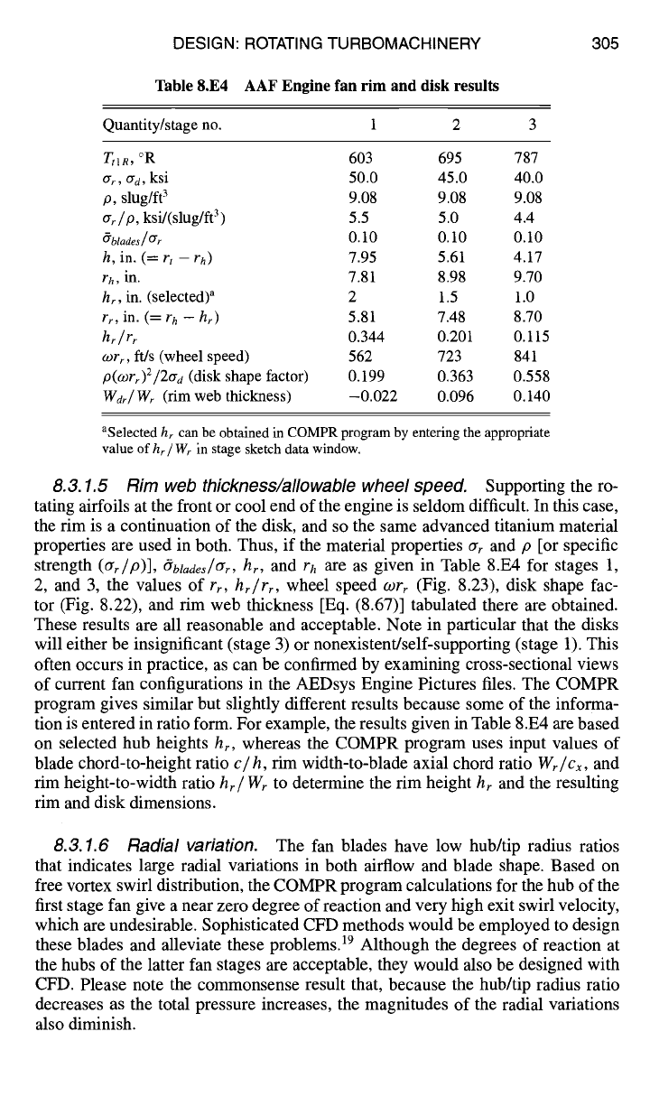
DESIGN: ROTATING TURBOMACHINERY 305
Table 8.E4 AAF Engine fan rim and disk results
Quantity/stage no. 1 2 3
T,1 R, °R 603 695 787
ar, crd, ksi 50.0 45.0 40.0
p, slug/ft 3 9.08 9.08 9.08
ar/p, ksi/(slug/ft 3 ) 5.5 5.0 4.4
~blades/ar
0.10 0.10 0.10
h, in. (= r,
- rh)
7.95 5.61 4.17
rh, in.
7.81 8.98 9.70
h~, in. (selected) a 2 1.5 1.0
rr, in. (= r h - hr) 5.81 7.48 8.70
hr/rr
0.344 0.201 0.115
~Orr, ft/s (wheel speed) 562 723 841
p(Wrr)2/2trd (disk shape factor) 0.199 0.363 0.558
Wdr/W~ (rim web thickness) -0.022 0.096 0.140
aSelected
hr can be obtained in COMPR program by entering the appropriate
value of hr / Wr in stage sketch data window.
8.3.1.5 Rim web thickness~allowable wheel speed.
Supporting the ro-
tating
airfoils at the front or cool end of the engine is seldom difficult. In this case,
the rim is a continuation of the disk, and so the same advanced titanium material
properties are used in both. Thus, if the material properties ar and p [or specific
strength (Crr/p)], #btades/Crr, hr, and rh are as given in Table 8.E4 for stages 1,
2, and 3, the values of rr, hr/rr, wheel speed o)r r (Fig. 8.23), disk shape fac-
tor (Fig. 8.22), and rim web thickness [Eq. (8.67)] tabulated there are obtained.
These results are all reasonable and acceptable. Note in particular that the disks
will either be insignificant (stage 3) or nonexistent/self-supporting (stage 1). This
often occurs in practice, as can be confirmed by examining cross-sectional views
of current fan configurations in the AEDsys Engine Pictures files. The COMPR
program gives similar but slightly different results because some of the informa-
tion is entered in ratio form. For example, the results given in Table 8.E4 are based
on selected hub heights hr, whereas the COMPR program uses input values of
blade chord-to-height ratio c/h, rim width-to-blade axial chord ratio Wr/Cx, and
rim height-to-width ratio hr/Wr
to
determine the rim height hr and the resulting
rim and disk dimensions.
8.3.1.6 Radial variation. The fan blades have low hub/tip radius ratios
that indicates large radial variations in both airflow and blade shape. Based on
free vortex swirl distribution, the COMPR program calculations for the hub of the
first stage fan give a near zero degree of reaction and very high exit swirl velocity,
which are undesirable. Sophisticated CFD methods would be employed to design
these blades and alleviate these problems. 19 Although the degrees of reaction at
the hubs of the latter fan stages are acceptable, they would also be designed with
CFD. Please note the commonsense result that, because the hub/tip radius ratio
decreases as the total pressure increases, the magnitudes of the radial variations
also diminish.