Kutz M. Handbook of materials selection
Подождите немного. Документ загружается.

668 NONDESTRUCTIVE INSPECTION
Log (relative exposure)
Density Log(B /B)
0
4
3
2
1
321
0
Type K
Type F
Type M
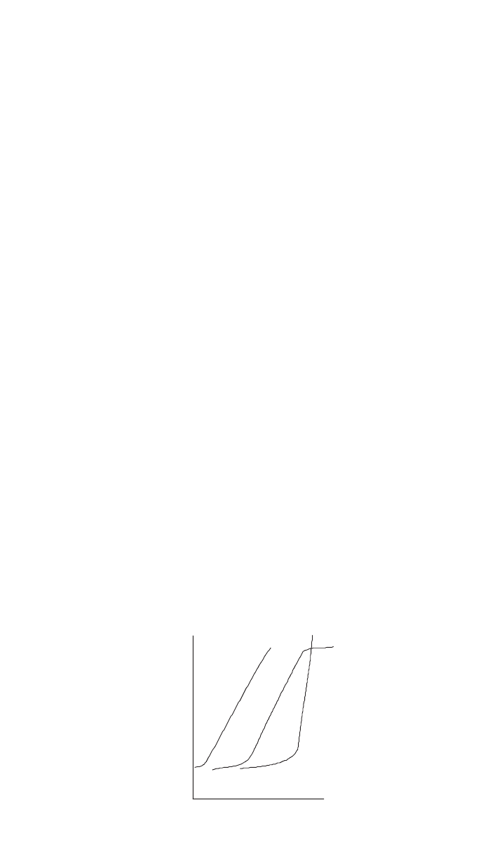
Fig. 17 Density or darkness of X-ray film versus relative exposure for three common films.
ment by its weight fraction in the material and summing these quantities. Mul-
tiplying this quantity by the density of the material yields its attenuation
coefficient. This procedure is not often used in practice because the results are
valid only for a narrow band of wavelengths. In practice, radiographic equiva-
lency factors are used instead. This process points out that each element in a
material contributes to the attenuation coefficient by an amount proportional to
its atomic percentage in the composition.
4.4 Film-Based Radiography
The classical method of recording an X-ray image is with film. Because of the
continued importance of this medium of recording and the fact that much of the
technology associated with it is applicable to newer solid-state recording meth-
ods, this next section explores film radiography in some detail.
The relationship between the darkness produced on an X-ray film and the
quantity of radiation falling on it is shown in Fig. 17. This is a log-log plot of
darkness or film density and relative exposure. Varying the time of exposure,
intensity of the beam, or specimen thickness will change the film density. The
slope of the curve along its linear portion is referred to as the film gamma,
␥
.
Film has characteristics that are quite analogous to electronic devices. For ex-
ample, the greater the gamma or amplification capability of the film, the smaller
its dynamic range—the range of exposures over which density is linearly related
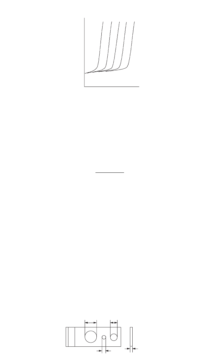
to thickness. If it is necessary to use a high gamma film to detect very subtle
flaws in a part with a wide range of thickness, then it will be necessary to expose
several different film types in the same cassette—see Fig. 18. In this way, each
film will be optimized for flaw detection in a narrow range of thickness of the
part.
Using what we have learned so far, it is possible to calculate the minimum
detectable flaw size for a specific RT situation. A method is even available to
check the radiographic procedure to determine if it has achieved the calculated
capability. This procedure does not ensure that the radiograph was taken with
the specimen in the proper orientation; it only provides a method of checking
the radiographic procedures for proper execution. This is covered in the section
on penetrameters (Section 4.5).
4 RADIOGRAPHY 669
Log (relative exposure)
Density, Log(B /B)
0
4
3
2
1
123
0
12345
Fig. 18 Density versus relative exposure for films that could be used in a multiple film expo-
sure to obtain optimum flaw delectability in a complex part.
T
T
2T
4T
No. #
Fig. 19 Schematic of typical film penetrameter.
Using knowledge of the minimum density difference that is detectable by the
average radiographic inspector, the following relationship may be derived that
relates the radiographic sensitivity S to both RT parameters and thickness
changes in the specimen:
2.3
S ⫽
␥
⫻
⫻ x
where S is the radiographic sensitivity in percent,
␥
is the film gamma for the
exposure conditions used,
is the attenuation coefficient of the specimen ma-
terial, and x is the maximum thickness of the part associated with the radio-
graphic film. To check the RT process to determine if this sensitivity was
achieved the radiographer uses a penetrameter.
4.5 The Penetrameter
An example of a penetrameter is shown schematically in Fig. 19, while its image
on a radiograph is shown schematically in Fig. 20. This type of penetrameter
was chosen because it is easily related to the previous discussion of radiographic
sensitivity. This penetrameter is quite simply a thin strip of metal or polymeric
material in which three holes of varying sizes are machined or punched. It is
composed of the same material as the specimen and has a thickness of 1, 2, or
4% of its maximum thickness. The holes in the penetrameter have diameters
that are 1, 2, and 4 times its thickness. The sensitivity achieved for each radi-
ographic is determined by noting the smallest hole just visible in the thinnest

670 NONDESTRUCTIVE INSPECTION
N
N
o
o
.
.
#
#
Fig. 20 Radiograph of the penetrameter shown in Fig. 19. The 1T hole is just visible indicating
the resolution obtained in the radiograph.
Table 3 Sensitivity versus the Smallest
Hole Just Visible in the Thinnest
Penetrameter
Sensitivity, S (%)
Quality Level
(%T–Hole Diameter)
0.7 1–1T
1.0 1–2T
1.4 2–1T
2.0 2–2T
2.8 2–4T
4.0 4–2T
penetrameter on a film and by using Table 3. By calculating the radiographic
sensitivity and then noting the level achieved in practice, the radiographic pro-
cess can be quantitatively evaluated. While this procedure does not offer any
guarantee of flaw detection, it is quite useful in evaluating the effectiveness the
RT process.
Almost all variables of the radiographic process may be easily and rapidly
changed with the aid of tables, graphs, and nomograms, which are usually pro-
vided by film manufacturers free of charge. For more information in this regard
the reader is referred to the commercial literature.
4.6 Real-Time Radiography
While film radiography represents the bulk of the radiographic NDE performed
at this time, new methods of both recording the data and analyzing it are coming
into widespread usage. For example, filmless radiography (FR) or real-time (RT)
radiography testing uses solid-state detectors or television detection and image-
processing methods instead of film to record the image. These methods have
several advantages along with some disadvantages. For example, FR permits
viewing a radiographic image while the specimen is being moved. This often
permits the detection of flaws that would normally be missed in conventional
film radiography because of the limited number of views or exposures usually
taken—remember that the X-ray beam must pass along a cracklike flaw in order
to be detectable. Additionally, the motion of some flaws enhances their detect-
ability because they present the inspector with a different image as a function
of time than he or she is accustomed to viewing. Additionally, image enhance-
4 RADIOGRAPHY 671
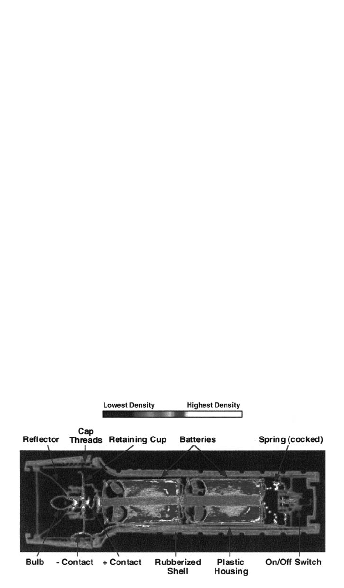
Fig. 21 Computed tomography of flashlight.
ment techniques can now be economically applied to these images because of
the availability of inexpensive, fast computing hardware. The price to be paid
for these advantages is the lower resolution of the FR image compared to film.
Typical resolution capabilities of FR systems are in the range from 4 to perhaps
20 line pairs/mm, while film resolution capabilities are in the range from 10 to
100 line pairs/mm. This means some very fine flaws may not be detectable with
FR and the inspector must resort to film. However, in cases where resolution is
not the limiting factor in delectability, the benefits of software-enabled image
enhancement can be significant. While the images on film may also be enhanced
using the image-processing schemes, they cannot be performed in real or near
real time, as can be done with a totally electronic system.
4.7 Computed Tomography
Another advance in industrial radiography with and unrealized capability to link
NDE with engineering design and analysis is computed tomography (CT). The
principle advantage of this method is that it produces an image of a thin slice
of the specimen under examination. This slice is parallel to the path of the X-
ray beam as it passes through the specimen as contrasted to the image produced
by classical radiography, where the image is formed on a plane perpendicular
to the path of the X-ray beam on passage through the specimen. The classical
radiographic image can be difficult to interpret because it collapses all of the
image information in the specimen between the source of X-rays and the re-
cording media, whereas the CT image is computed or calculated from X-ray
intensity data and does not contain information from planes outside the thin
slice.
This comparison is best explained with images with these two modalities.
Figure 13 shows a typical radiograph where one can easily see the image of the
top and bottom surfaces of the tube under inspection. Contrast this with the
image in Fig. 21 that shows a CT slice through a flashlight. The individual
672 NONDESTRUCTIVE INSPECTION
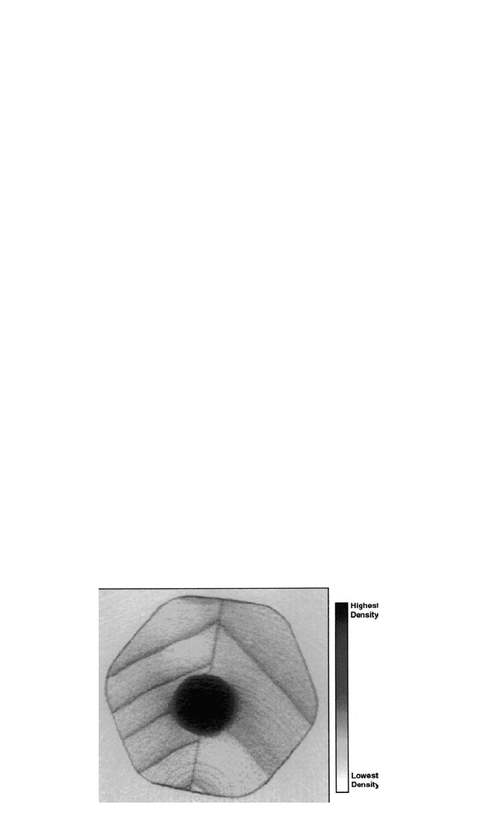
Fig. 22 Computed tomograph of a pencil. The reader will note the yearly growth rings and
even the growth variations within a single growing season.
components of the flashlight are easily visible and any misplacement of its com-
ponents or defects in its assembly could be easily detected. An image on a finer
scale than this can clearly reveal microstructural details of a material as shown
in Fig. 22. Everyone will recognize that this is a pencil. Not only are the key
features clearly visible, but even the growth rings of the wood are clearly visible.
In fact, the details of the growth during each season are visible as rings within
rings. The information in the CT image contrasted with conventional radiographs
is striking. First, the delectability of a defect is independent of its position in
the image. This is not the case with the classical radiograph where the defect
delectability decreases significantly with depth in the specimen because the de-
fect represents a smaller change in the attenuation of the X-ray beam as the
depth increases. Second, the defect delectability is very nearly independent of
its orientation. This again is clearly not the case with classical radiography. The
extent to which CT could alter radiography is only now being explored. New
applications are being discovered frequently. For example, with the computed
digital image of CT it is possible to search for various flaw conditions using
computer analysis and relieve the inspector of much of the tedium of examining
structures for the odd flaw. In addition, it is possible to link the digital CT image
with finite-element analysis software to examine precisely how the flaws present
will affect such parameters as the stress distribution, heat flow, etc. With little
effort one could analyze the full three-dimensional performance of many engi-
neering structures.
5 EDDY CURRENT INSPECTION
Eddy current methods are used principally to inspect electrically conducting
components for near-surface flaws such as cracks and voids, heat treatment con-
dition, external dimensions and wall thickness of thin-walled tubing, and thick-
ness of nonconducting coatings on a metallic substrate.
17
Quite often several of
these conditions can be monitored simultaneously if instrumentation capable of
multiple frequencies is used and the results are analyzed using computer algo-
rithms.

5 EDDY CURRENT INSPECTION 673
This NDE method is based on the principle that eddy currents are induced in
a conducting material when a coil or array of conductors (probe) with an alter-
nating or pulsating electric current is placed in close proximity to the surface of
the material. The induced currents create an electromagnetic field that opposes
the field of the inducing coil in accordance with Lenz’s law. The eddy currents
circulate in the part in closed, continuous paths, and their magnitude depends
on several variables. The first is the magnitude and frequency of the current in
the inducing coil. Second, is the coil’s shape and position relative to the surface
of the part, the electrical conductivity, magnetic permeability, and shape of the
part. Finally, there are the influences of any discontinuities or inhomogenities
within the material. Therefore, the eddy currents are useful in exploring these
properties of test materials, as well as any discontinuities or variations in ge-
ometry and dimensions of materials.
5.1 Skin Effect
Since alternating currents are necessary to eddy current inspection, information
from the inspection is limited to the near-surface region by the skin effect. Within
the material, the eddy current density decreases rapidly with distance from the
surface. The density of the eddy current field falls off exponentially with depth
and diminishes to a value of about 37% of the at-surface value at a depth referred
to as the standard depth of penetration (SDP). The SDP in meters may be cal-
culated with the simple formula
1
SDP ⫽
兹
ƒ
where ƒ is the test frequency in hertz,
is the test material’s electrical conduc-
tivity in mho/m (see Appendix B for a table of conductivities for common
metals), and
is its permeability in H/m. This latter quantity is the product of
the relative permeability of the specimen, 1.0 for nonmagnetic materials, and
the permeability of free space, which is 4
⫻ 10 H/m.
⫺
7
5.2 Impedance Plane
While the SDP is used to give an indication of the depth from which useful
information can be obtained, the choice of the independent variables in most
test situations is usually made using the impedance plane diagram suggested by
Forster.
66
It is theoretically possible to calculate the optimum inspection param-
eters from numerical codes based on Maxwell’s equations, but this is a tedious
task that is justified only in special situations.
The eddy currents induced at the surface of a material are time varying and
have amplitude and phase. The complex impedance of the coil used in the in-
spection of a specimen is a function of a number of variables. The effect of
changes in these variables can be conveniently displayed with the impedance
diagram that displays the variations in amplitude and phase of the coil impedance
as functions of the dependent variables specimen conductivity, thickness, and
distance between the coil and specimen or lift-off. For the case of an encircling
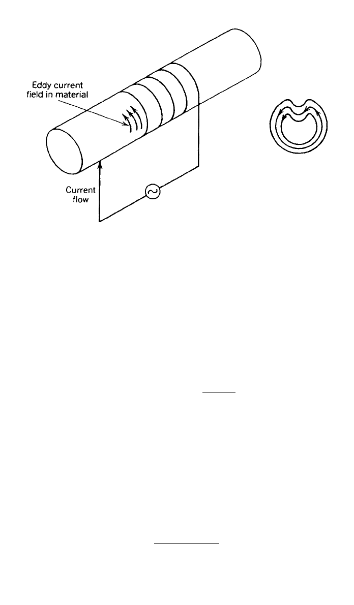
coil on a solid cylinder, shown schematically in Fig. 23, the complex impedance
plane is displayed in Fig. 24. The reader will note that the ordinate and abscissa
674 NONDESTRUCTIVE INSPECTION
Fig. 23 Schematic representation for an eddy current inspection of a solid cylinder.
Also shown are the eddy current paths within the cross section of the cylinder
in the vicinity of the crack.
are normalized by the inductive reactance of the empty coil. This eliminates the
effects of the coil/specimen geometry. The numerical values are shown on the
large curve, called reference numbers. These numbers are used to combine
the effects of conductivity and size of the test specimen and the frequency of
the measurement into a single parameter. In this way, the diagram is useful for
most test conditions encountered by the NDE inspector. The reference numbers
shown on the outermost curve are obtained with the following relationship, for
nonmagnetic materials:
Reference # ⫽ r兹2
ƒ
where r is the radius of the bar in meters, ƒ is the frequency of the test in hertz,
is the magnetic permeability of free space (4
⫻ 10 H/m), and
is the
⫺
7
conductivity of the specimen in mho/m. The outer curve in Fig. 24 is useful
only for the case where the coil is the same size as the solid cylinder, which
almost never happens. For those cases when the coil is larger than the test
specimen, which is usually the case, a coil-filling factor is calculated. This is
quite easily accomplished with the following formula:
2
diameter
specimen
N ⫽
冉冊
diameter
coil
Figure 24 shows the impedance plane with a curve for a cylinder/coil inspection
geometry with a fill factor of 0.75. Note that the reference numbers on the
ordinate representing the different fill factors can be determined by projecting a
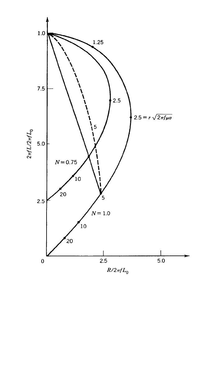
5 EDDY CURRENT INSPECTION 675
Fig. 24 Normalized impedance diagram for a long encircling coil on a solid, nonferromagnetic
cylinder. For N ⫽ 1 the coil and cylinder have the same diameter, while for N ⫽ 0.75 the coil is
approximately 1.155 times larger than the cylinder.
straight line from point 1.0 on the ordinate to the reference number of interest.
This is shown for reference number 5.0. Both the fill factor and the reference
number change when the size of either the specimen or coil changes. This is
shown in Fig. 24 for solid cylinders. The other geometry of general interest is
the thin-walled tube—remember that the skin effect limits the thickness of a
conductor that may be inspected.
For an infinitely thin-walled tube the impedance plane is shown in Fig. 25.
Also included in this figure is the curve for a solid cylinder. The curve segments
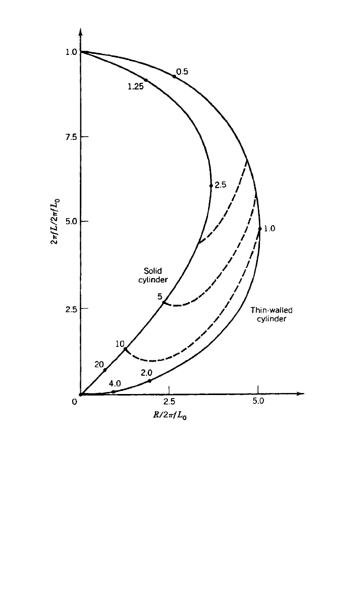
676 NONDESTRUCTIVE INSPECTION
Fig. 25 Normalized impedance diagram for a long encircling coil on both a solid and
thin-walled conductive but nonferromagnetic cylinders. The dashed lines represent the
effects of varying wall thickness.
that connect these two extreme cases are for walled cylinders of varying thick-
ness. The semicircular curve for the thin cylinder is used in the same manner
as described above.
5.3 Lift-Off of Inspection Coil from Specimen
In many inspection situations the only independent variables are frequency and
lift-off. High frequencies are used for detecting defects such as surface cracks
or corrosion, and low frequencies are mostly used to detect deeply buried de-
fects. While it is possible to change the coil shape and measurement configu-
ration, the reader is referred to the literature for a discussion of the effects of
these more complex variables. The relationships discussed thus far would seem
5 EDDY CURRENT INSPECTION 677
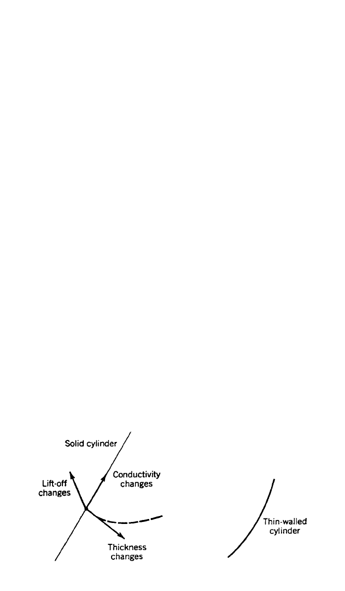
Fig. 26 Effects of various changes in inspection conditions on local signal changes
in the impedance plane of Fig. 25. Phase differentiation is relatively easily accomplished
with current instrumentation.
of little practical usefulness. However, if a small section of Fig. 25 is expanded
as shown in Fig. 26, then their utility of a well-chosen frequency will become
apparent. In this figure, vectors represent small changes in thickness, lift-off,
and conductivity. Since these vectors all point in different directions, the signals
that they represent have different phases. Thus, instrumentation with phase dis-
crimination circuitry can differentiate among these different conditions. Changes
in conductivity can arise from several different conditions, the most important
of which is due to material inhomogeneity. For example, aluminum alloys can
have quite different conductivities depending either on their heat treatment or
the presence of cracks or voids. These flaws decrease the apparent conductivity
of the specimen because the eddy currents must either travel a longer distance
to complete their circuit or the material presents a more resistive path. There
are other important eddy current inspection capabilities that cannot be covered
in this brief description of this important tool. These include the inspection of
ferromagnetic alloys, plate and sheet stock, and the measurement of film thick-
ness on metallic substrates. For a treatment of these and other special applica-
tions of eddy current NDE, the reader is referred to the Nondestructive Testing
Handbook, Vol. 4, Electromagnetic Testing.
17
There are many methods of making and displaying eddy current measure-
ments. Two of the more common methods are shown schematically in Fig. 27.
In the absolute coil arrangement very accurate measurements can be made of
the difference between the two different samples. One can be a standard, while
the other is the component in question. In the differential coil arrangement the
differences between two variables at two slightly different locations are com-
pared. For this arrangement slightly varying dimensions and conductivity are not
sensed, while singularities such as cracks or voids are highlighted even in the
presence of other more slowly changing variables. The electronic circuitry used
to accomplish each of these measurements can vary dramatically depending on
the inspection. This aspect of eddy current testing will not be covered here, and
the reader is referred to the manufacturers and engineering literature for details
of the appropriate electronic circuitry.
