Jenkins N., Strbac G., Ekanayake J. Distributed Generation
Подождите немного. Документ загружается.


that approaches the short-circuit rating of the switchgear and other components of
the system. This is typically the case in the centres of cities and in industrial plants
where the short-circuit level is kept high to minimise voltage changes caused by the
high currents drawn when connecting large loads and starting large motors. If the
short-circuit level is already high, then adding any distributed generation may lead
to excessive short-circuit levels. In these circumstances the distributed generator
will be refused permission to connect to the network.
The rapid and reliable detection of faults using short-circuit current from dis-
tributed generators is difficult due to their relatively small ratings and the long
clearance times of distribution protection systems with only small fault currents. A
small distributed generator, with the same per unit machine parameters on its rating
as that of a large generator, will provide fault current only in proportion to the
machine sizes and ratings. Distribution networks are often protected with time-
delayed over-current protection that, because of the way it is set (or graded), can
require fault currents considerably higher than the circuit continuous rating in order
to operate quickly. Thus, the ability of a small generator to provide adequate fault
current requires careful attention during the design of the distributed generation
scheme.
4.2.1 Synchronous generators
The fault current of a synchronous generat or into a three-phase fault depends on the
rotor construction. If the machine is a salient-pole machine, both the direct axis (i.e.
the axis of the field winding) and the quadrature axis reactances (synchronous,
transient and sub-transient) contribute to the fault current [1,2]. For a cylindrical
pole machine the direct axis has the same value of reactances as the quadrature
axis, and the fault current contribution to a three-phase fault is usually described by
an expression of the form:
IðtÞ¼E
F
1
X
þ
1
X
0
1
X
e
t=T
0
þ
1
X
00
1
X
0
e
t=T
00
cosðwt þ lÞ
E
F
X
00
e
t= T
a
cosðlÞð4:1Þ
where X = synchronous reactance, X
0
= transient reactance, X
00
= sub-transient
reactance, E
F
= pre-fault internal voltage, T
0
= transient short-circuit time constant,
T
00
= sub-transient short-circuit time constant, T
a
= armature (DC) time constant,
l = angle of the phase at time zero, w = system angular velocity.
Note: Equation (4.1) is written in the conventional form [1,3–5, Tutorial II].
The sub-transient, transient and synchronous reactances are used to represent the
performance of the machine at different times after the fault, defined by the cor-
responding time constants. The armature (DC) time constant is used to describe the
decay of the DC component of the fault current.
The last term of (4.1) describes the DC component that depends on the point-
on-wave at which the fault occurs, while the remainder describes the 50/60 Hz
Fault currents and electrical protection 97

component. The short-circuit time constants (T
0
and T
00
) and the armature
time constant (T
a
) are not fixed values but depend on the location of the fault. In
particular,
T
a
¼
ðX
00
þ X
e
Þ
wðR
a
þ R
e
Þ
ð4:2Þ
where X
e
= external reactance (to the fault), R
e
= external resistance (to the fault),
R
a
= armature resistance.
Synchronous machine impedances have X/R ratios that are much larger than
those of distribution circuits. Hence, a fault close to a synchronous generator will
have an armature time constant (T
a
) and DC component that lasts much longer than
for a remote fault. This is an important consideration for distributed generation
schemes. Traditional, passive distribution systems, fed from high- voltage (HV)
networks through a succession of transformers and circuits with some resistance
can be considered to have fault currents with a very rapid decay of the DC offset
and an essentially constant AC component. In contrast, faults close to generators, or
large motors, will have slower decaying DC offset and decaying AC components.
This is recognised in IEC or BS EN 60909 [6] that recommends two different
calculation approaches for these two situations, i.e. the ‘far-from-generator-short-
circuit’ and the ‘near-to-generator-short-circuit’. Engineering Recommendation
G74 [7] also discusses the various computer-based modelling approaches that may
be used to represent this effect.
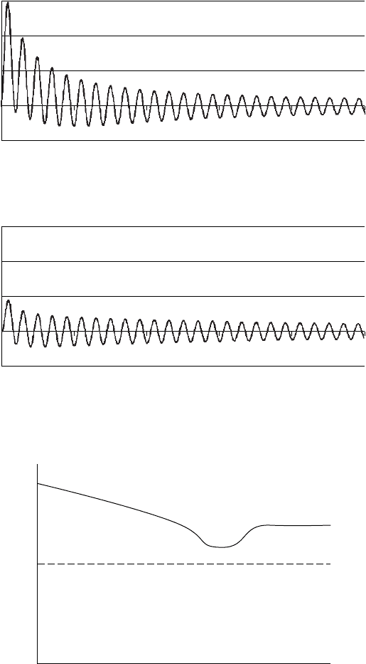
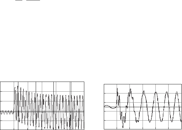
Figure 4.1 shows a simulat ion of the response of a synchronous generator to a
close-up and remote fault. (For clarity, only the phase with maximum offset is
shown.) Obviously the fault current is much larger for the close-up fault than for
the remote fault. The close-up fault shows the longer decay in the DC component
and the reducing AC component. The remote fault shows the very rapid decay of
the DC component and only a very small reduction in the AC current with time.
A circuit breaker close to a synchronous generator has a more onerous duty when
breaking fault current than one in a passive distribution network and so old dis-
tribution circuit breakers, which were never intended to be used close to synchronous
generators, may need to be changed when distributed generation is installed.
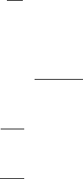
Figure 4.2 shows a curve that is a typical of those supplied by manufacturers to
describe the fau lt current capability of a small synchronous generator on to a three-
phase fault at its terminals. In this case the current is expressed in rms values with
logarithmic scales on the axes. It may be seen that the expected decay occurs up to,
say, 200 ms but then the excitation system operates to boost the fault current back
up to three times full-load output (by increasing E
F
in (4 .1)). This is necessary as
distribution protection is usually time-graded and so sustained fault current is
required if current operated protection is to function effectively. This ability to
boost the fault current depends critically on the excitation scheme that has been
chosen. Depending on the generator design, a 3 per unit (pu) sustained fault current
on to a terminals short circuit may require ‘field forcing’ to an internal voltage of
8–10 times that needed at no-load.
98 Distributed generation
A paper by Griffith [8] gives an excellent review of various types of generator
excitation including a discussion of field forcing and the possible use of voltage-
controlled over-current protection for small distributed generator schemes.
Sub-transient
Transient
Steady state
⫺5
0
0 100 200 300
Time (ms)
(
a
)
Close-u
p
fault
400 500
5
Current (pu)
10
15
⫺5
0
0 100 200 300
Time (ms)
(
b
)
Remote fault
400 500
5
Current (pu)
10
15
Figure 4.1 Fault current of a synchronous generator (phase with maximum offset)
0.1
1
10
0.001 0.01 0.1 1.0 10
Current (kA)
Full load
3 ⫻ Full load
Time
(
s
)
Figure 4.2 Short-circuit decrement curve for a small synchronous generator
Fault currents and electrical protection 99
4.2.2 Induction generators
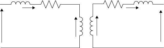
The behaviour of an induction generator under fault conditions is rather different to
that of a synchronous generator. The operation of an induction machine with a
three-phase fault on the network is described using the transformer equivalent
circuit of an induction machine shown in Figure 4.3 (see also Figure II.14). In
Figure 4.3 the rotor resistances and reactances are locked rotor values. In this book,
it has been assumed that these values are constant and do not depend on the slip.
3
E
r
2
refers to the induced emf when the rotor is rotating and s is the slip.
R
1
X
1
R
2
sX
2
V
1
I
1
I
2
E
r
2
E
1
V
r
Figure 4.3 Induction machine equivalent circuit (motor convention). The rotor is
short circuited in a squirrel-cage machine, V
r
is then zero.
If a fault occurs on the power system, the terminal voltage, V
1
, will be reduced
(the magnitude of the reduction depends on the location of the fault). However,
immediately after the fault, the magnetic field, f, will not change, thus E
1
will be
same as its pre-fault value. So the stator current will be reversed and the induction
machine feeds into the fault. The magnitude of fault current will depend on the
relative magnitudes and phases of E
1
and V
1
.
Under normal operating conditions or for a remote fault (where V
1
is suffi-
ciently large to supply the magnetising current), the stator produces a magnetic field
which rotates at w
s
. When the rotor is rotating at w
r
, there will be relative motion
between the rotor conductors and the stator magnetic field equal to w
s
w
r
¼ sw
s
.
Thus the magnitude of the rotor-induced emf E
r
2
is given by:
E
r
2
¼ sw
s
fk ð4:3Þ
where f is the magnetic field at the air gap and k is a proportional constant.
3
For a single-cage rotor construction, the rotor resistance and reactance are essentially constant. How-
ever for a double-cage (deep bar) rotor construction, the rotor resistance decreases with the slip, and the
rotor reactance increases with the slip [9]. During normal operation the slip (s) is small (around 1%)
and the frequency of the induced rotor currents is low. Hence, the currents are distributed across the
depth of the rotor bars to give a low value of resistance and a high value of reactance. When the slip
approaches 1 (locked rotor conditions) the currents are concentrated near the surface of the rotor by the
skin effect, and the rotor resistance increases and the rotor reactance decreases.
100 Distributed generation
The rotor current is given by:
I
2
¼
E
r
2
R
2
þ jsX
2
ð4:4Þ
The situation is different for a three-phase fault at the term inals of the induction
generator. Due to the fault, V
1
becomes zero. The magnetic field (f) will not diminish
immediately after the fault but will cease to rotate. As the rotor continues to rotate at
w
r
, the relative movement between the rotor conductors and the magnetic field is
equal to w
r
. Thus the magnitude of the rotor-induced emf E
r
2
fault
is given by [9,11]:
E
r
2
fault
¼ w
r
fk ð4:5Þ
Then, the frequency of the rotor-induced emf is equal to w
r
/2p. Therefore, the
rotor reactance will be ( w
r
/w
s
)X
2
(as the locked rotor value X
2
is calculated for the
synchronous frequency, w
s
/2p). Thus, the rotor current during a fault is given by:
I
2 fault
¼
E
r
2
fault
R
2
þ jðw
r
=w
s
ÞX
2
ð4:6Þ
From (4.3) to (4.6) and with w
r
=w
s
1:
I
2 fault
I
2
1=s
1 þ jðX
2
=R
2
Þ
ð4:7Þ
Using (4.7), for a 2 MW induction generator with R
2
¼ 0:0055 pu and
X
2
¼ 0:1 pu, it was calculated that the fault current (immediately after the fault) at
an operating slip of 1% is about 5.5 times the rated current. However, as there is
no reactive power source to sustain the magnetising current, the magnetic field
collapses (thus E
r
2
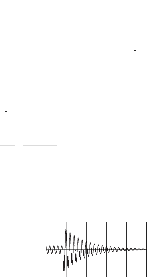
collapses) and the fault current decays to zero. Figure 4.4 shows
one phase of a simulation of a 2 MW, 690 V induction generator. It may be seen
that the fault current decays within 100–200 ms.
0 0.1
0.2
Time
(
s
)
0.3 0.4 0.5
⫺2.5
⫺1.5
⫺0.5
0.5
1.5
2.5
Fault current (kA)
Figure 4.4 Fault current of an induction generator with a three-phase fault at its
terminals (phase shown with minimum DC offset)
Fault currents and electrical protection 101
An expression similar to (4.1) may be used to describe the fault current con-
tribution of an induction generator to a three-phase fault at its terminals. However,
due to difficulties with obtaining data it is often reduced to:
IðtÞ¼
V
1
X
00
½cosðwt þ lÞe
t=T
00
þ cosðlÞe
t=T
a
ð4:8Þ
where (see Figure II.15 for resistances and reactances)
X
00
¼ X
1
þ
X
0
2
X
m
X
0
2
þX
m
T
00
¼
X
00
wR
0
2
T
a
¼
X
00
wR
1
V
1
is the magnitude of the network voltage (sometimes increased by a safety
factor to account for the voltage variations depending on the time and place,
changing of transformer taps, neglecting load and capacitance, and the sub-
transient behaviour of generators and motors [7]).
w ¼ð1 sÞw
s
w
s
ðas s is very smallÞ
X
0
2
and R
0
2
are the stator-referred rotor reactance and resistance.
As for a synchronous generator, any external impedance involved must be
added to the stator impedance.
Unbalanced faults on the network may lead to sustained fault currents from
induction generators and in some cases a rise in current on the unfaulted phase(s).
Appropriate computer simulations are required for an accurate representation of the
behaviour of an induction generator feeding a sustained unbalanced fault.
The fault current from an induction generator is generally not relied upon for
the operation of any protective relays. Therefore, when a fault occurs on a dis-
tribution system connected to an induction generator, the fault current from the
network source is used to operate the distribution system over-current protection.
This isolates the generator and so over-voltage, over-frequency or loss-of-mains
relays are then used to trip its local circuit breaker and prime mover. This sequential
tripping of the generator using voltage, frequency or over-speed protection is
necessary as the induction generator is not capable of providing reliable, sustained
fault current.
4.2.3 Doubly fed induction generators
The fault current contribution of DFIGs is discussed in References 9, 11 and 12.
Their fault current contribution depends significantly on the pre-fault operating
102 Distributed generation
condition. Assuming that the rotor-injected voltage is unchanged immediately after a
fault, the DFIG fault current is explained using Figure 4.3 (in this case the rotor is not
short circuited and the converter connected to the rotor continues to inject a voltage).
When a three-phase short circuit occurs at the terminals of the DFIG, the induced
emf on the rotor circuit is given by (4.5). The subsequent rotor fault current will be
governed by the difference between the rotor-induced emf and the injected voltage.
If the back-to-back power electronic converters connected to the DFIG rotor
are rated to take large fault currents, then there exist three current components on
the stator [9,11].
1. A DC component on the rotor circuit decaying at a time constant of
T
00
¼ X
00
2
=wR
0
2
(where X
00
2
¼ X
2
þðX
1
X
m
=X
1
þ X
m
Þ and R
0
2
is the stator-
referred rotor resistance). The magnetic field created by this current rotates
with the rotor and creates an alternating current in the stator.
2. A DC component on the stator circuit that decays at a time constant of
T
a
¼ X
00
1
=wR
1
(where X
00
1
¼ X
1
þðX
2
X
m
=X
2
þ X
m
Þ).
3. A sustained fault current due to the voltage fed by the rotor converters (the
term I
m
cos wt þ lðÞin (4.9)).
Therefore, an expression similar to (4.8) may be obtained for the DFIG with
sufficiently highly rated converter s [9,11]:
IðtÞ¼
V
1
X
00
X
2
m
X
1
X
2
cosðwt þ lÞe
t=T
00
þ cosðlÞe
t=T
a
þ I
m
cosðwt þ lÞð4:9Þ
In this equation, w ¼ð1 sÞw
s
and s depends on the pre-fault operating con-
dition. The value of s may vary between þ0.4 and 0.2 (this depends on the wind
turbine design).
Figure 4.5 shows a simulation of the stator and rotor current of a DFIG when
the generator is operating with a constant mechanical torque of T
m
= 1.0 pu and a
three-phase fault was applied at t = 10 s.
⫺15
9.9 10 10.1
Time (s)
10.2 10.3 10.4 10.5
⫺7
⫹1
⫹9
⫹17
⫹25
kA
Stator current
⫺15
⫺9
⫺3
⫹3
⫹9
⫹15
kA
9.9 10 10.1
Time (s)
10.2 10.3 10.4 10.5
Rotor current
Figure 4.5 Simulation of fault current of a DFIG without crowbar operation [13]
Fault currents and electrical protection 103
Practical DFIG converters are often designed to carry only a limited over-load
current. Therefore, excessively large rotor currents are not allowed to flow in the
rotor circuit. In order to protect the power electronic converters, a crowbar is often
employed that short circuits the rotor circuit through an impedance. The subsequent
operation of the DFIG is then very similar to an induction generator with increased
rotor impedance (rotor impedance plu s crowbar impedance). Therefore, (4.8) can
be used for the DFIG fault current with increased R
0
2
and/or X
0
2
(this depends on the
crowbar impedance, but typically a resistor is used in the crowbar circuit) and
w ¼ð1 sÞw
s
.
4.2.4 Generators connected through power electronic converters
IEC/BS EN 60909 [7] requires that power electronic motor drives that can operate
regeneratively are considered for their contribution to initial short-circuit current
but not to any sustained short-circuit current. They are represented as an equivalent
motor with a locked rotor current of 3 rated current. The CIGRE report on dis-
persed generation [14] indicates that a fault current only equal to rated current may
be expected.
The actual behaviour of the generator/converter system when supplying fault
current depends both on its power circuit and control system. To protect the semi-
conductor devices in a converter against large transient current flowing during a
fault, an instantaneous over-current shut-down protection element is normally
employed [15]. When the fault current reaches the over-current trip level, the over-
current protection activates within a few microseconds. Therefore, the fault current
contribution from a converter-connected distributed generator is very low. If the
power circuit of the converter consists of thyristors (current source converter), then
the fault current contribution during the first few cycles may be about 2–3 times the
rated current of the converter. If the converter is IGBT based (voltage source con-
verter), then the converter will not generally be able to provide a fault current of
more than 120% higher than its rating. However, there are voltage source converter-
based systems that can provide up to 2–3 times the rated current for a short time.
For a voltage source converter to continue to operate under unbalanced faults
the control systems (including the phase locked loop) must be robust. Simple
designs of voltage source converters used with small distri buted generators are
unlikely to stay operating during network unbalances.
4.3 Fault current limiters
Fault currents of the network, after the connection of a new distributed generator,
may be greater than the short-circuit capability of the existing switchgear and
cables. This may require replacing the switchgear (and other equipment) with that
of a higher short-circuit rating. However, such upgrades are not easy due to:
(a) high replacement cost, (b) disruption to the supply during the construction
period and (c) the short-circuit ratings of presently available plant may soon
become inadequate. Other than replacing the existing switchgear, there are several
104 Distributed generation
methods that can be used to reduce the fault current in the power system to an
acceptable leve l. These methods include: (a) network splitting, (b ) current limiting
reactors, (c) current limiting fuses and (d) fault current limiters [16,17].
4.3.1 Network splitting
If the network is split, often by opening substation bus-section circuit breakers, the
sources of short-circuit current are separated thus increasing the impedance
between the sources and the fault. This in turn reduces the fault current. The con-
sequence of network splitting is that the number of duplicate supply paths to a load
is reduced with potential reduction of reliability [17].
4.3.2 Current limiting reactors
A reactor can be placed in series with the generator circuit to increase the impedance
to the fault and so reduce the fault current. Despite a voltage drop and a power loss
associated with a reactor during normal operation, current limiting reactors are used
in practice due to their relatively low cost of implementation and maintenance.
4.3.3 Current limiting fuses
Current limiting fusegear consists of two parallel conductors: a main conductor and
a parallel fuse. Under normal operation, the load current flows through the main
conductor. During a fault, a tripping device disconnects the main conductor,
transferring the fault current to the parallel fuse with a high breaking capacity,
which limits the fault current during the initial rise of the first 50/60 Hz cycle [2].
4.3.4 Fault current limiters
Fault current limiters (FCLs) have a high impedance during a fault while having a
low impedance under normal operating conditions. Depending on the technology
used to obtain the required impedance characteristic, FCLs can be categorised into
three main groups: (a) superconducting fault current limiters (SFCL) [16,18,19],
(b) magnetic fault current limiters (MFCL) [20,21] and (c) static fault current
limiters [22,23].
There are two major types of the SFCL namely, resistive and inductive. The
resistive type is essentially a superconductor connected in series with the power
circuit [18,24,25]. The superconductor shows a negligible resistivity below a cri-
tical temperature (T
c
) and a critical current density (J
c
) (superconducting state), and
as soon as T
c
or J
c
are surpassed, the resistivity of the material increases rapidly
(normal state) [26]. The superconductor is located in a liquid nitrogen bath referred
to as ‘cryostat’. At liquid nitrogen temperature (77 K), the superconductor shows a
negligible resistance. During a fault as a high current passes through the super-
conductor, both current density and temperature increase above T
c
and J
c
. This in
turn takes the superconductor to its normal state, thus showing a high resistance in
series with the power line. This series resistor effectively limits the fault current.
Inductive SFCLs can broadly be divided into screened-core and saturated-core
types [18,25]. The screened-core design has a primary copper winding connected in
Fault currents and electrical protection 105
series with the line, a superconducting cylinder (which forms a single turn second-
ary) and an iron core. The primary winding in this device is usually wound over the
superconducting cylinder. Therefore, the superconductor acts as a magnetic shield
or screen preventing primary winding flux from entering the iron. This can be
visualised as a transformer with a short-circuited secondary thus giving negligible
impedance in series with the line [18]. During a fault the superconductor moves to
its normal state, thus the transformer primary reactance acts in series with the line.
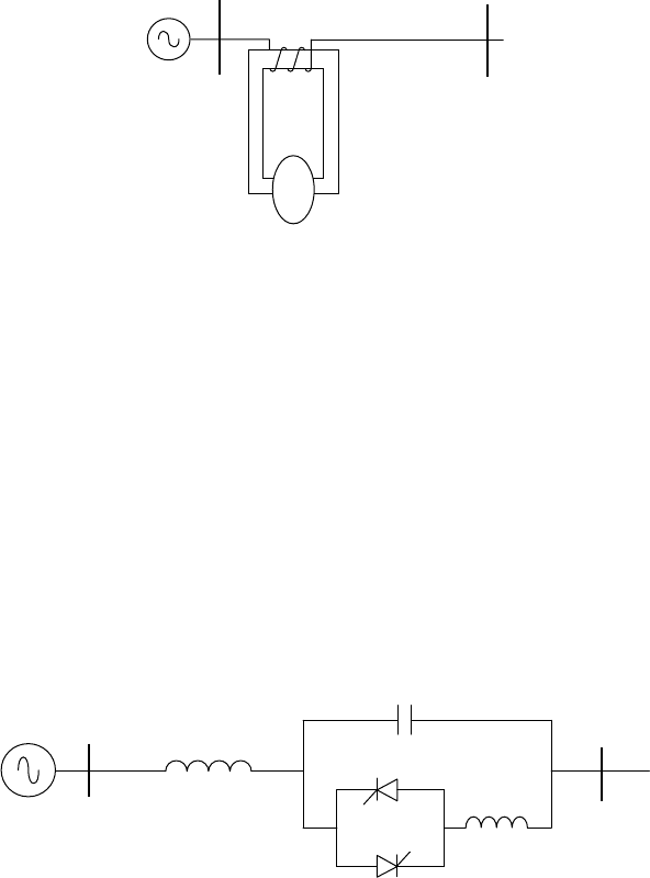
A saturated-core SFCL and some MFCL designs operate essentially on the same
basic principle. A simple construction of a saturated-core FCL is shown in Figure 4.6.
Arrangement for biasing
the core into saturation
ℑ
Figure 4.6 Saturated-magnet SFCL and its operating principle
The magnetic core of the winding is biased into saturation by a DC magnetic
field produced by a superconductor [25] or by a permanent magnet [21]. With low
operating currents, the device presents only a low saturated inductance to the cir-
cuit. During a fault the large fault current brings the core out of saturation, thereby
presenting a high impedance to the power circuit. A single core only acts for one
half of the AC waveform, and a similar device that is acting on the other half cycle
of the AC waveform is required to provide current limiting in both cycles [21].
A static fault current limiter is shown in Figure 4.7. In normal operation the
thyristor switch is OFF and current flows through Reactor 1 and the capacitor. The
reactances of the capacitor and Reactor 1 are chosen to be equal so that the series
combination shows very small impedance. During a fault the thyristor switch is
turned ON, the capacitor is effectively by-passed and the impedance of the circuit
becomes reactive thus limiting the fault current.
Reactor 1
Capacitor
Reactor 2
Thyristor
switch
Figure 4.7 A static fault current limiter
106 Distributed generation