Jenkins N., Strbac G., Ekanayake J. Distributed Generation
Подождите немного. Документ загружается.


If the current from the generator is I
1
, by applying Kirchhoff’s current law to
Bus 1:
I
1
¼ I
12
þ I
13
¼
ðV
1
V
2
Þ
Z
12
þ
ðV
1
V
3
Þ
Z
13
ð3:10Þ
Defining the admittance as the reciprocal of the impedance (thus Y
12
¼ 1=Z
12
and
Y
13
¼ 1= Z
13
), (3.10) was rewritten as:
I
1
¼ Y
12
ðV
1
V
2
ÞþY
13
ðV
1
V
3
Þ
¼ðY
12
þ Y
13
ÞV
1
Y
12
V
2
Y
13
V
3
ð3:11Þ
By applying Kirchhoff’s current law to Bus 2 and using the corresponding
admittances:
I
2
¼ I
21
þ I
23
¼ Y
12
ðV
2
V
1
ÞþY
23
ðV
2
V
3
Þ
¼ðY
12
þ Y
23
ÞV
2
Y
12
V
1
Y
23
V
3
ð3:12Þ
where I
2
is the negative value of the load current drawn by the load P
2
þ jQ
2
.
By applying Kirchhoff’s current law to Bus 3:
I
3
¼ I
31
þ I
32
¼ Y
13
ðV
3
V
1
ÞþY
23
ðV
3
V
2
Þ
¼ðY
13
þ Y
23
ÞV
3
Y
13
V
1
Y
23
V
2
ð3:13Þ
where I
3
is the negative value of the load current drawn by the load P
3
þ jQ
3
.
Equations (3.11), (3.12) and (3.13) in matrix form:
I
1
I
2
I
3
2
4
3
5
¼
ðY
12
þ Y
13
ÞY
12
Y
13
Y
12
ðY
12
þ Y
23
ÞY
23
Y
13
Y
23
ðY
13
þ Y
23
Þ
2
4
3
5
|fflfflfflfflfflfflfflfflfflfflfflfflfflfflfflfflfflfflfflfflfflfflfflfflfflfflfflfflfflfflfflfflfflfflfflfflfflfflfflffl{zfflfflfflfflfflfflfflfflfflfflfflfflfflfflfflfflfflfflfflfflfflfflfflfflfflfflfflfflfflfflfflfflfflfflfflfflfflfflfflffl}
Admittance matrix¼y
V
1
V
2
V
3
2
4
3
5
ð3:14Þ
For a general case with N busbars:
I
k
¼
X
N
i¼1
y
ki
V
i
¼ y
kk
V
k
þ
X
N
i¼1
i6¼k
y
ki
V
i
ð3:15Þ
where y
ki
is the element in the kth row and ith column of the admittance matrix.
Distributed generators and their connection to the system 67

From (3.15):
V
k
¼
I
k
y
kk
1
y
kk
X
N
i¼1
i6¼k
y
ki
V
i
ð3:16Þ
For a load:
V
k
I
k
¼ðP
k
þ jQ
k
Þ
I
k
¼
P
k
þ jQ
k
V
k
ð3:17Þ
Combining (3.16) and (3.17):
V
k
¼
1
y
kk
P
k
þ jQ
k
V
k
X
N
i¼1
i6¼k
y
ki
V
i
2
6
4
3
7
5
ð3:18Þ
For power-flow studies, one node is always specified as a voltage of constant
magnitude and angle and is called the slack bus. For studies of distributed gen-
eration the slack bus is often a strong node of the main power system.
The voltage of a busbar to which a large synchronous generator is connected
can be controlled by the generator excitation control. Therefore, such a busbar is
specified as a generator bus, or a PV bus, where the magnitude of the voltage and
active power are specified.
The third category of busbar is where a load is connected so that both active
and reactive powers are specified (PQ bus).
An induction generator can be represented by a PQ bus with a negative active
power and a positive reactive power as it generates P and absorbs Q. A distributed
generator with a power electronic interface can be used for power factor and/or
voltage control. If the voltage control is activated then it may be represented as a
PV bus. If only power factor correction is activated then it can be represented by a
PQ bus with a negative active power.
If there are N number of busbars in a power system, when one busbar is defined as
the slack or reference bus there will be (N1) simultaneous equations (3.18). The
unknowns in these equations depend on the category of the busbar. For example for a
generator bus, unknowns are the reactive power and voltage angle, whereas for a load
bus the unknowns are the magnitude and angle of the voltage. Once the (N1) equa-
tions are established, they can be solved using an iterative method. Two commonly
used techniques are the: Gauss–Siedal method and Newton–Raphson method [4,5].
1. Gauss–Siedal method
Choose an initial voltage for load busbars, say V
ð0Þ
i
¼ 1:0ff0
for i = 1 to N.
68 Distributed generation

From (3.18):
V
ð1Þ
k
¼
1
y
kk
P
k
þ jQ
k
ðV
ð0Þ
k
Þ
X
N
i¼1
i6¼k
y
ki
V
ð0Þ
i
2
6
4
3
7
5
Now solve for V
ð1Þ
k
for all the busbars. The iterative process can be accelerated
if all the calculated values of V
ð1Þ
k
are used for subsequent calculations. For example
when calculating V
ð1Þ
3
, the calculated value of V
ð1Þ
2
is used.
The process is repeated until:
V
ðnþ1Þ
k
V
ðnÞ
k
e
where e is a constant of convergence.
See Example 3.2 for details of the steps involved in this calculation method.
2. Newton–Raphson method
Equation (3.18) was applied to the three bus system shown in Figure 3.23. As
busbar 1 is the slack bus (where the voltage is known), (3.18) was only applied to
two PQ buses, i.e. busbars 2 and 3.
V
2
¼
1
y
22
P
2
þ jQ
2
V
2
X
3
i¼1
i6¼2
y
2i
V
i
2
6
4
3
7
5
ð3:19Þ
V
3
¼
1
y
33
P
3
þ jQ
3
V
3
X
3
i¼1
i6¼3
y
3i
V
i
2
6
4
3
7
5
ð3:20Þ
Equations (3.19) and (3.20) were rewritten as:
f
1
ðV
2
; V
3
Þ¼C
1
ð3:21Þ
f
2
ðV
2
; V
3
Þ¼C
2
ð3:22Þ
where C
1
¼ y
21
V
1
and C
2
¼ y
31
V
1
are constants.
V
ð0Þ
2
and V
ð0Þ
3
are the initial estimates of solutions to (3.21) and (3.22)
and DV
ð0Þ
2
and DV
ð0Þ
3
are the values by which initial estimates differ from the correct
solutions.
f
1
ðV
ð0Þ
2
þ DV
ð0Þ
2
, V
ð0Þ
3
þ DV
ð0Þ
3
Þ¼C
1
ð3:23Þ
f
2
ðV
ð0Þ
2
þ DV
ð0Þ
2
, V
ð0Þ
3
þ DV
ð0Þ
3
Þ¼C
2
ð3:24Þ
Distributed generators and their connection to the system 69
From Taylor’s expansion neglecting higher-order derivates:
f
1
ðV
ð0Þ
2
, V
ð0Þ
3
ÞþDV
ð0Þ
2
@f
1
@V
2
V
ð0Þ
2
þDV
ð0Þ
3
@f
1
@V
3
V
ð0Þ
3
¼ C
1
ð3:25Þ
f
2
ðV
ð0Þ
2
, V
ð0Þ
3
ÞþDV
ð0Þ
2
@f
2
@V
2
V
ð0Þ
2
þDV
ð0Þ
3
@f
2
@V
3
V
ð0Þ
3
¼ C
2
ð3:26Þ
In matrix form:
C
1
f
1
ðV
ð0Þ
2
, V
ð0Þ
3
Þ
C
2
f
2
ðV
ð0Þ
2
, V
ð0Þ
3
Þ
"#
¼
@f
1
@V
2
@f
1
@V
3
@f
2
@V
2
@f
2
@V
3
"#
V
ð0Þ
2
, V
ð0Þ
3
|fflfflfflfflfflfflfflfflfflfflfflfflfflfflffl{zfflfflfflfflfflfflfflfflfflfflfflfflfflfflffl}
Jacobian matrix ½4;5
DV
ð0Þ
2
DV
ð0Þ
3
"#
ð3:27Þ
Equation (3.27) is solved to obtain DV
ð0Þ
2
and DV
ð0Þ
3
.ThenV
2
and V
3
were updated as:
V
ð1Þ
2
¼ V
ð0Þ
2
þ DV
ð0Þ
2
V
ð1Þ
3
¼ V
ð0Þ
3
þ DV
ð0Þ
3
The same procedure was repeated until jV
ðnþ1Þ
k
V
ðnÞ
k
je, where e is a constant of
convergence.
For a large meshed network where there are PV buses and PQ buses, the formation
of Jacobian matrix is more complex and more details can be found in Referen ces 4 and 5.
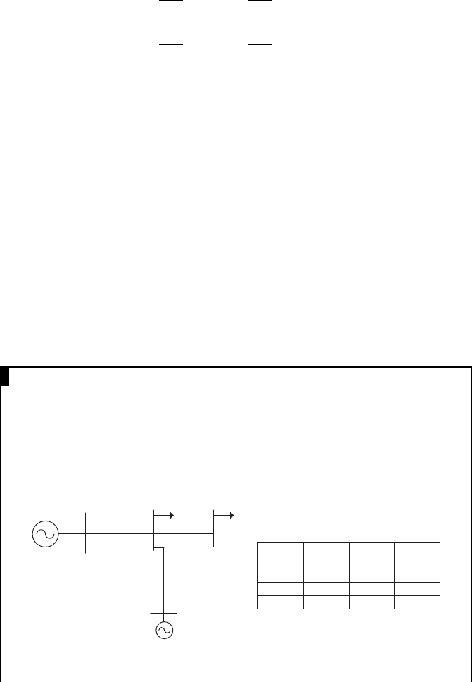
EXAMPLE 3.3
A large generator, G1,
3
is connected to Bus 1 of Figure E3.4 and maintains the
voltage of that bus at 1:1ff0
. Two loads connected to Bus 2 and 4 are 1 þ j0.5 and
0.5 þ j0.25 pu respectively. DG1 (a distributed generator) generates active power
of 0.5 pu and absorbs reactive power of 0.2 pu. All the per unit quantities are on a
10 MVA base. Use the Gauss–Seidel method to determine the busbar voltages.
Bus 1
Bus 2
Bus 3
Bus 4
DG1
G1
From
bus
To bus R (pu) X (pu)
1 2 0.02 0.04
2 4 0.01 0.02
2 3 0.01 0.02
Figure E3.4
3
In a study of Distributed Generation G1 represents the main power system.
70 Distributed generation

Since Z
12
¼0:02þj0:04 pu, Y
12
¼1=ð0:02þj0:04 Þ¼1=ð0:0447ff63:4
Þ¼
22:36ff63:4
¼10:0j20:0
Similarly: Y
23
¼ 1=ð0:01 þ j0:02Þ¼20:0 j40: 0 and Y
24
¼ 1=ð0:01 þ
j0:02Þ¼20:0 j40:0
Therefore the admittance matrix
¼
10 20j 10 þ 20j 00
10 þ 20j 50 100j 20 þ 40j 20 þ 40j
0 20 þ 40j 20 40j 0
0 20 þ 40j 020 40j
2
6
6
6
4
3
7
7
7
5
Bus 1 is chosen as the slack bus. Therefore, (3.18) was applied to Buses 2, 3
and 4.
For Bus 2:
V
2
¼
1
y
22
P
2
þ jQ
2
V
2
X
4
i¼1
i6¼2
y
2i
V
i
2
6
4
3
7
5
¼
1
50100j
1þj0:5
V
2
þð10 20jÞ1:1ff0
þð2040jÞV
3
þð2040jÞV
4
ð3:28Þ
For an iterative solution, (3.28) was manipulated into:
V
ð1Þ
2
¼
1
ð50 100jÞ
11 22j þ
1 þj0:5
ðV
ð0Þ
2
Þ
þð20 40jÞV
ð0Þ
3
þð20 40jÞV
ð0Þ
4
"#
ð3:29Þ
For Bus 3:
4
V
3
¼
1
y
33
P
3
þ jQ
3
V
3
X
4
i¼1
i6¼3
y
3i
V
i
2
6
4
3
7
5
¼
1
20 40j
0:5 þ j0:2
V
3
þð20 40jÞV
2
4
In (3.18), it was assumed that P and Q are flows from the busbar to the load. For the DG1,
P flows towards the busbar and Q flows from the busbar.
Distributed generators and their connection to the system 71

Similarly to (3.29) but assuming that V
ð1Þ
2
has already been calculated:
V
ð1Þ
3
¼
1
ð20 40jÞ
0:5 þ j0:2
ðV
ð0Þ
3
Þ
þð20 40jÞV
ð1Þ
2
"#
ð3:30Þ
For Bus 4:
V
4
¼
1
y
44
P
4
þ jQ
4
V
4
X
4
i¼1
i6¼4
y
4i
V
i
2
6
4
3
7
5
¼
1
20 40j
0:5 þ j0:25
V
4
þð20 40jÞV
2
Similarly as (3.30):
V
ð1Þ
4
¼
1
ð20 40jÞ
0:5 þ j 0: 25
ðV
ð0Þ
4
Þ
þð20 40j ÞV
ð1Þ
2
"#
ð3:31Þ
To solve (3.29), (3.30) and (3.31) the Gauss-Siedal method is used. With
V
ð0Þ
2
, V
ð0Þ
3
and V
ð0Þ
4
equal to 1:0ff0
, from (3.29):
V
ð1Þ
2
¼
1
ð50 100jÞ
1122j þ
1þj0:5
1:0ff0
þð2040jÞ1:0ff0
þð2040jÞ1:0ff0
¼1:012ff0:3
With V
ð1Þ
2
¼ 1:012ff0:3
and V
ð0Þ
3
¼ 1:0ff0
, from (3.30):
V
ð1Þ
3
¼
1
ð20 40jÞ
0:5 þ j0:2
1:0ff0
þð20 40jÞ1:012ff0:3
¼ 1:013ff 0: 3
With V
ð1Þ
2
¼ 1:012ff0:3
and V
ð0Þ
4
¼ 1:0ff0
, from (3.31):
V
ð1Þ
4
¼
1
ð20 40jÞ
0:5 þ j0:25
1:0ff0
þð20 40jÞ1:012ff0:3
¼ 1:002ff0:8
The following table shows the values of busbar 2, 3 and 4 voltages. The
iterations were repeated until all voltages converged.
72 Distributed generation
Iteration V
2
V
3
V
4
11:012ff0:3
1:013ff0:3
1:002ff0:8
21:018ff0:5
1:019ff0:2
1:008ff0:9
31:023ff0:6
1:024ff0
1:013ff1:0
41:027ff0:7
1:028ff0:1
1:017ff1:1
.
.
.
.
.
.
.
.
.
.
.
.
19 1:043ff1:0
1:044ff0:4
1:033ff1:4
20 1:043ff1:0
1:044ff0:4
1:033ff1:4
This example network was implemented in one of the commercially
available load flow package (IPSA) and the voltages at busbars were
obtained. The final voltages are V
2
¼ 1:044ff1:0
, V
3
¼ 1:045ff0:4
and V
4
¼ 1:034ff1:4
.
Example 3.3 illustrates that although the Gauss–Seidel method is simple
in concept, it can be slow to converge for some networks and parameters.
Thus all modern power-flow programs use the Newton–Raphson technique or
a derivative of it.
3.3.3 Symmetrical fault studies
Fault calculations can be categorised by whether the currents and voltages are
symmetrical or asymmetrical across the three phases. If a three-phase fault occurs
then the network remains electrically balanced and the AC components of the
resulting fault currents are symmetrical. A line-to-ground, line-to-line or line-to-
line-to-ground fault results in asymmetrical fault currents.
Analysis of symmetrical faults is very similar to AC system analysis discussed
in Tutorial Chapter IV [4,5,15]. Only one phase needs to be considered as the others
are the same magnitude displaced by 120
.
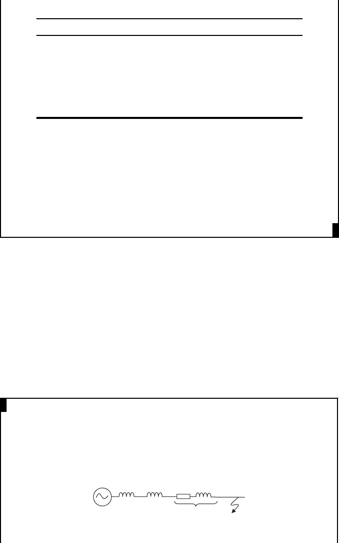
EXAMPLE 3.4
In the circuit shown in Example IV.2 (in Tutorial Chapter IV), calculate the
fault current resulting from a fault at the end of the line.
Answer:
The per unit equivalent circuit is given by:
1 pu 0.918 +
j
4.59
j 0.1
j 0.15
Distributed generators and their connection to the system 73
Neglecting resistance,
5
the fault current = 1/(0.15 þ 0.1 þ 4.59)
= 0.207 pu.
With S
b
100 MVA and V
L
33 kV, the current base is:
I
b
¼
S
b
ffiffiffi
3
p
V
L
¼
100 10
6
ffiffiffi
3
p
33 10
3
¼ 1749:5A
Therefore, the fault current = 1749.5 0.207 = 361.5 A.
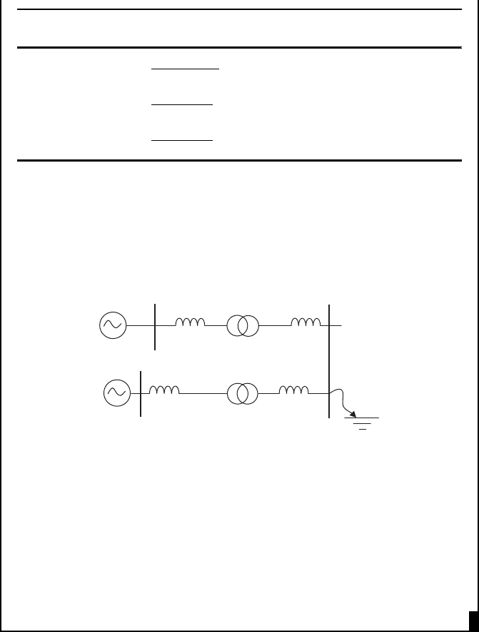
EXAMPLE 3.5
The drawing shows the synchronous generator of a solar thermal power plant
connected to a radial system.
5 km
220:69 kV
100 MVA
18 %
Grid in-feed
10 MVA
X″ = 0.2 pu
220 kV
69:22 kV
2 x 20 MVA
15 %
25 km
50 km
The parameters of the overhead lines are:
Nominal voltage of circuit Impedance of line (W/km)
220 kV j3.0
69 kV 0.5 þ j1.0
22 kV 0.5 þ j0.25
Using a 100 MVA base, change all the par ameters into per unit. A three-
phase short circuit fault occurs at the 69 kV busbar of the 69/22 kV trans-
former substation. Calculate the fault current in per unit and amperes that
flows from the infinite busbar and the generator.
Answer:
X
00
is the reactance of the generator at the moment a fault occurs. On 100
MVA base X
00
= 0.2 100/10 = j2 pu.
The following table gives the base impedance (Z
B
) and the per unit
reactance of each line, neglecting resistance.
5
If all network resistances are neglected, the resulting fault currents will be slightly high and so
the calculation is generally conservative. The j operator may be ignored.
74 Distributed generation
Nominal voltage
of circuit (kV) Z
B
(W)
Reactance
of line (W)
Reactance
of line (pu)
220
ð220 10
3
Þ
2
100 10
6
¼ 484 j150 j0.31
69
ð69 10
3
Þ
2
100 10
6
¼ 47 : 6 j25 j0.525
22
ð22 10
3
Þ
2
100 10
6
¼ 4:84 j1.25 j0.258
220 kV:69 kV transformer reactance on 100 MVA base = j0.18 pu.
69 kV:22 kV transformer reactance on 100 MVA base = j0.15 100 /40 =
j0.375.
Therefore, the per unit equivalent of the system may be drawn as (note
that the circuit is rearranged to make the subsequent calculations clearer):
j 0.18
1 pu
j0.31
j0.52
j0.258
1 pu
j2
j 0.375
Fault current flowing from the infinite busbar = 1/(0.31 þ 0.18 þ 0.525)
= 0.985 pu.
Fault current flowing from the generator = 1/(2 þ0.375 þ 0.258) = 0.38 pu.
The base current on 220 kV network is 100 10
6
=
ffiffiffi
3
p
22010
3
¼262:4A.
Therefore, the fault current flowing from the infinite busbar = 0.985
262.4 = 258.5 A.
The base current on the 22 kV network is 100 10
6
=
ffiffiffi
3
p
22 10
3
¼
2624:3A.
Therefore, the fault current flowing from the infinite busbar = 0.38
2624.3 = 997.2 A.
3.3.4 Unbalanced (asymmetrical) fault studies
The currents in each phase resulting from an unbalanced fault (line-groun d, line-
line or line-line-ground) are not equal and so are calculated using the method
of symmetrical components, discussed in Section IV.4 [4,5,15]. When using
symmetrical components, the power system is represented as three sequence
Distributed generators and their connection to the system 75
networks: positive, negative and zero. The relationship between the phase voltages
and sequence network voltages is given by (IV.33) and repeated here:
6
V
A0
V
A1
V
A2
2
4
3
5
¼
1
3
11 1
1 ll
2
1 l
2
l
2
4
3
5
V
A
V
B
V
C
2
4
3
5
ð3:32Þ
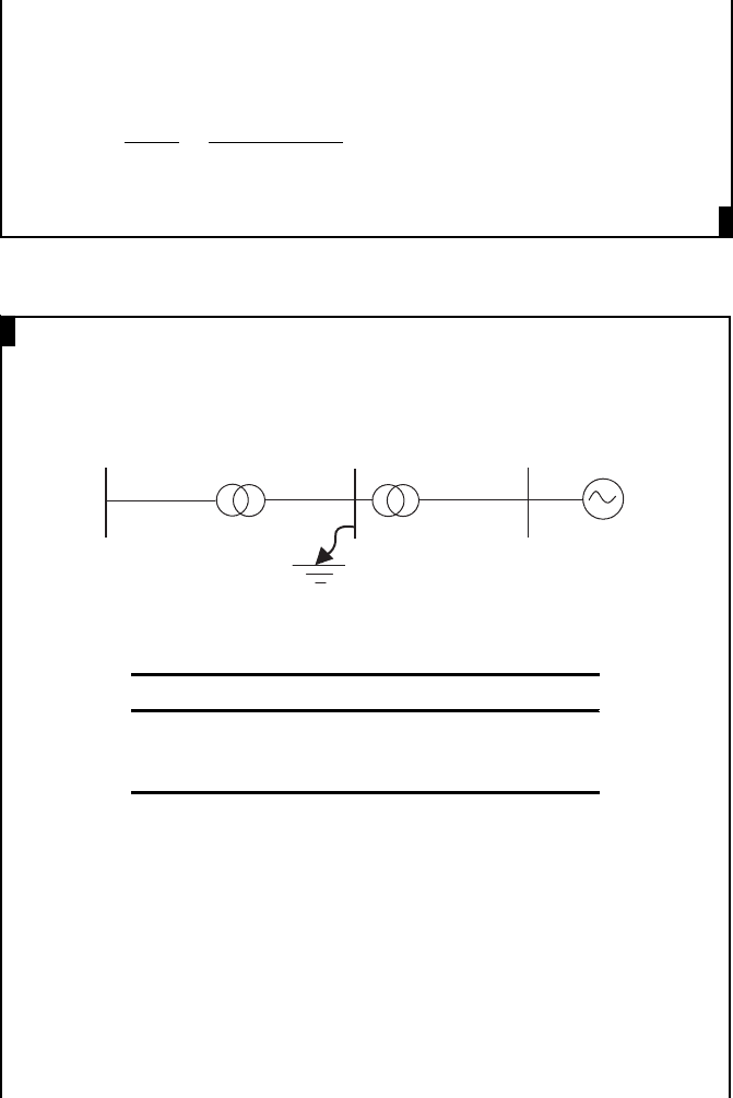
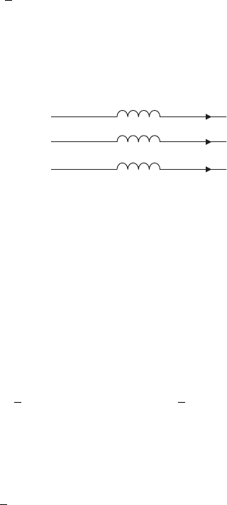
To illustrate the formation of sequence networks, the line section shown in
Figure 3.24 is used.
X
X
X
I
A
I
B
I
C
A
B
C
A′
B′
C′
Figure 3.24 Line section with pure reactances
The voltage and currents for the line section are:
V
AA
0
V
BB
0
V
CC
0
2
4
3
5
¼ X
I
A
I
B
I
C
2
4
3
5
ð3:33Þ
Three-phase voltage drops given by (3.33) were converted to three sequence
components by using (3.32):
V
AA
0
0
V
AA
0
1
V
AA
0
2
2
4
3
5
¼
1
3
11 1
1 ll
2
1 l
2
l
2
4
3
5
V
AA
0
V
BB
0
V
CC
0
2
4
3
5
¼
1
3
X
11 1
1 ll
2
1 l
2
l
2
4
3
5
I
A
I
B
I
C
2
4
3
5
ð3:34Þ
As (3.32) is also true for currents:
I
A0
I
A1
I
A2
2
4
3
5
¼
1
3
11 1
1 ll
2
1 l
2
l
2
4
3
5
I
A
I
B
I
C
2
4
3
5
ð3:35Þ
From (3.34) and (3.35):
V
AA
0
0
V
AA
0
1
V
AA
0
2
2
4
3
5
¼ X
I
A0
I
A1
I
A2
2
4
3
5
ð3:36Þ
6
l ¼ e
j2p=3
or 120
phase shift.
76 Distributed generation