Houze Robert A., Jr. Cloud Dynamics
Подождите немного. Документ загружается.

8.10 Downbursts 319
larlyfavored where propagating arc lines intersect each other or where an arc line
encounters pre-existing convection.
8.10 Downbursts
8.10.1
Definitions and Descriptive Models
We have seen that the downdraft is a salient feature of the thunderstorm circula-
tion. Sometimes the downdraft becomes locally very intense over a short period
oftime, in which case it is referred to as a downburst. The following definitions are
used to describe the phenomenon.F"
Downburst-An
area of strong winds produced by a downdraft over an area
from
< 1 to 10 km in horizontal dimension.
Macroburst-A
downburst that occurs over an area
>4
km in dimension and is
typically 5-30 min in duration.
Microburst-A
downburst that covers an area
<4
km in dimension and lasts
2-5 min. Differential velocity across the divergence center is
>
10m
s
-I.
Wet
microburst-A
microburst associated with >0.25 mm of rain or a radar
echo >35 dBZ in intensity.
Dry
microburst-A
microburst associated with <0.25 mm of rain or a radar
echo <35 dBZ in intensity.
The most scientific and public attention has been focused on the microburst,
largely because of the danger it poses for aircraft operations. The existence and
importance of this phenomenon were noted by Professor T. Fujita
235
in his investi-
gations of aircraft accidents and patterns of damage to crops and property by
violent winds that could not be explained by the vortical circulation patterns of
tornadoes. In contrast to tornadoes, downbursts produce patterns that reflect
strongly divergent and diffluent air motions at the ground. From surveying such
damage patterns, Fujita was led to hypothesize the air motion pattern in a micro-
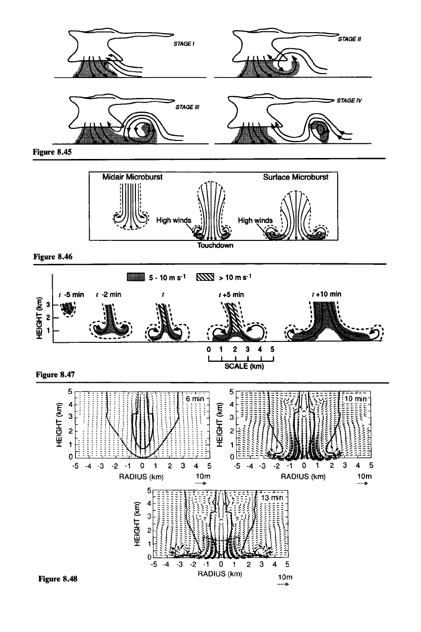
burst shown in Fig.
8.46. As can be seen from Fig. 8.47 and Fig. 8.48, this
conceptual model has proven accurate under scrutiny by Doppler radar observa-
tions and numerical modeling. Besides a shaft of strong downward velocity at its
center, the microburst is characterized when
it hits the ground by strong diver-
gence at its center and an accelerating outburst of strong winds in a vigorously
overturning gust-front head propagating more or less symmetrically away from
the center of the microburst. When the microburst contains rain, dust, or other
material from the surface, it can be seen visually (Fig.
8.49). Fujita conceptualized
234 These definitions are based on the somewhat varying definitions used by Fujita (1985), Fujita
and Wakimoto (1983), and Wilson et al. (1984).
235 Professor T. Fujita, through his dogged and enthusiastic observations of storms and storm
damage, is largely responsible for raising scientific and public consciousness about the downburst. He
coined and promoted the terminology
"downburst"
and "rnicroburst." Many of his investigations and
adventures in the pursuit of this subject are described in his two books
The Downburst: Microburst
and
Macroburst (1985) and
DFW
Microburst on
August
2, 1985 (1986).
STAGE'
STAGE"
Figure 8.45
Midair
Microburst
~l~
Surface
Microburst
Figure 8.46
-
S
-10
m s-l
~
> 10
ms-'
I -S
min
I -2
min
I+Smin
~3
.:
~
2
-~
~
1
J:
0 2 3 4 S
I I I I I
SCALE (km)
Figure 8.47
1+10
min
,
,
6 min
:
\
V
:
.-
: :
:
:\L
j)-
: : :
2 3 4 5
10m
--I>
-2 -1 0 1
RADIUS (km)
4 5
10m
--I>
3
1
o
-5 -4 -3
~
4
3
3
-3 -2 -1 0 1 2
RADIUS (km)
o~~~~
-5 -4
E
~ 3
~
C) 2
[j
J:
-2 -1 0 1 2
RADIUS (km)
-4 -3
5
E 4
~
3
~
C) 2
m
J:
1
o
-5
Figure 8.48
8.10 Dowobursts
321
the downburst in three dimensions, as illustrated in Fig. 8.50. These sketches
illustrate the highly diffluent character of the surface wind and the expanding ring
vortex formed by the circular gust-front head. The purpose of Fig. 8.50b is to
show that some microbursts are associated with a small-scale cyclonic circulation
aloft. This cyclonic vorticity is, however, largely weakened by divergence [i.e.,
the stretching term
{w
z
in (2.59) is negative since W
z
< 0] before parcels reach the
ground.
8.10.2 Effects of Microbursts on Aircraft
Fujita's conceptual model has been used as an explanation for many aircraft
accidents. A pilot must make quick critical adjustments in flying through the wind
pattern of the microburst.
For
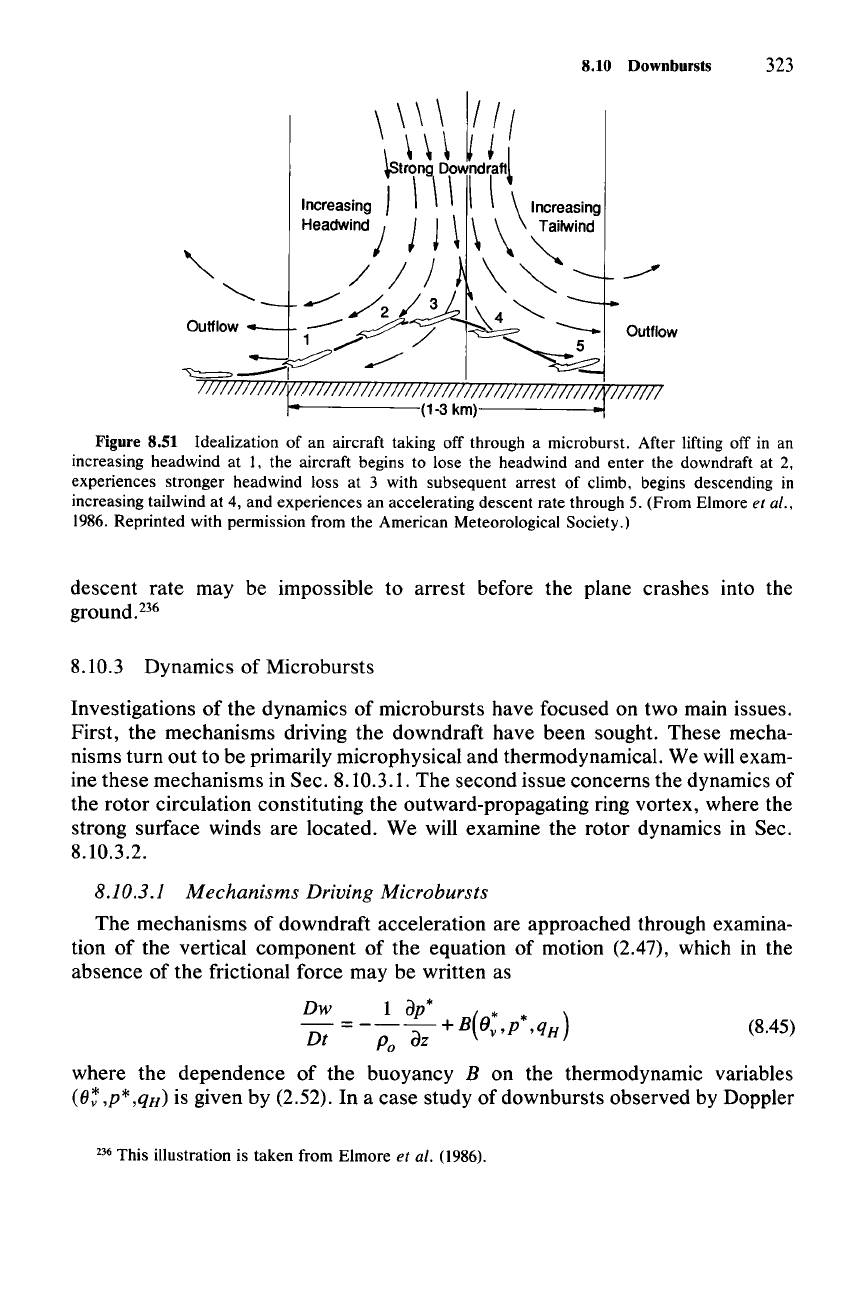
example, in taking off through a microburst (Fig.
8.51), the aircraft experiences an increase of headwind as it accelerates down the
runway. Then, the aircraft lifts off in the increasing headwind and begins to climb
(position 1).
Near
position 2, it encounters the microburst downdraft, and climb
performance is decreased. By position 3, the headwind is lost. Consequently,
airspeed is decreased, and lift and climb performance are further reduced. Added
to this is the increased downdraft at the microburst center. By position 4, all
available energy is needed to maintain flight, as the tailwind continues to increase.
However, there is no source on which the aircraft can draw to increase its poten-
tial energy (climb). A large aircraft is typically configured ("trimmed") such that
thrust, drag, lift, and weight are all in equilibrium. Thus, no pilot input is required
for the aircraft to maintain a set trajectory. Since the airspeed is below the trim
airspeed (decreasing lift and drag) at position 4, the airplane system will automati-
cally respond so as to regain the equilibrium condition by pitching the nose down-
ward. In the illustration, the pilot intervenes and compensates for this effect.
Should the pilot not fully compensate, a more radical descent could occur. The
descent rate continues to increase as the airplane passes through position 5.
Depending on the strength of the event, encounter altitude, aircraft performance
margin, and how quickly the pilot recognizes and reacts to the hazard, the high
Figure 8.45 Empirical model of the life cycle of a thunderstorm outflow. (From Wakimoto, 1982.
Reprinted with permission from the American Meteorological Society.)
Figure 8.46 Conceptual model of a microburst hypothesized to explain ground-damage patterns.
Three stages of development are shown. A midair microburst
mayor
may not descend to the surface.
If it does, the outburst winds develop immediately after its touchdown. (From Fujita,
1985.)
Figure 8.47 Empirical model of a microburst based on Doppler radar observations. Time t refers
to the arrival of divergent outflow at the surface. Shading denotes wind speed. (From Wilson
et al.,
1984. Reprinted with permission from the American Meteorological Society.)
Figure 8.48 Numerical-model simulation of a microburst at 6,
10, and 13 min after the initial model
time. Thick lines represent the 10 and 60 dBZ radar reflectivity contours (i.e., the precipitation field).
Dashed line encloses the area with temperature departures from ambient of less than
-I
K. (From
Proctor,
1988. Reprinted with permission from the American Meteorological Society.)
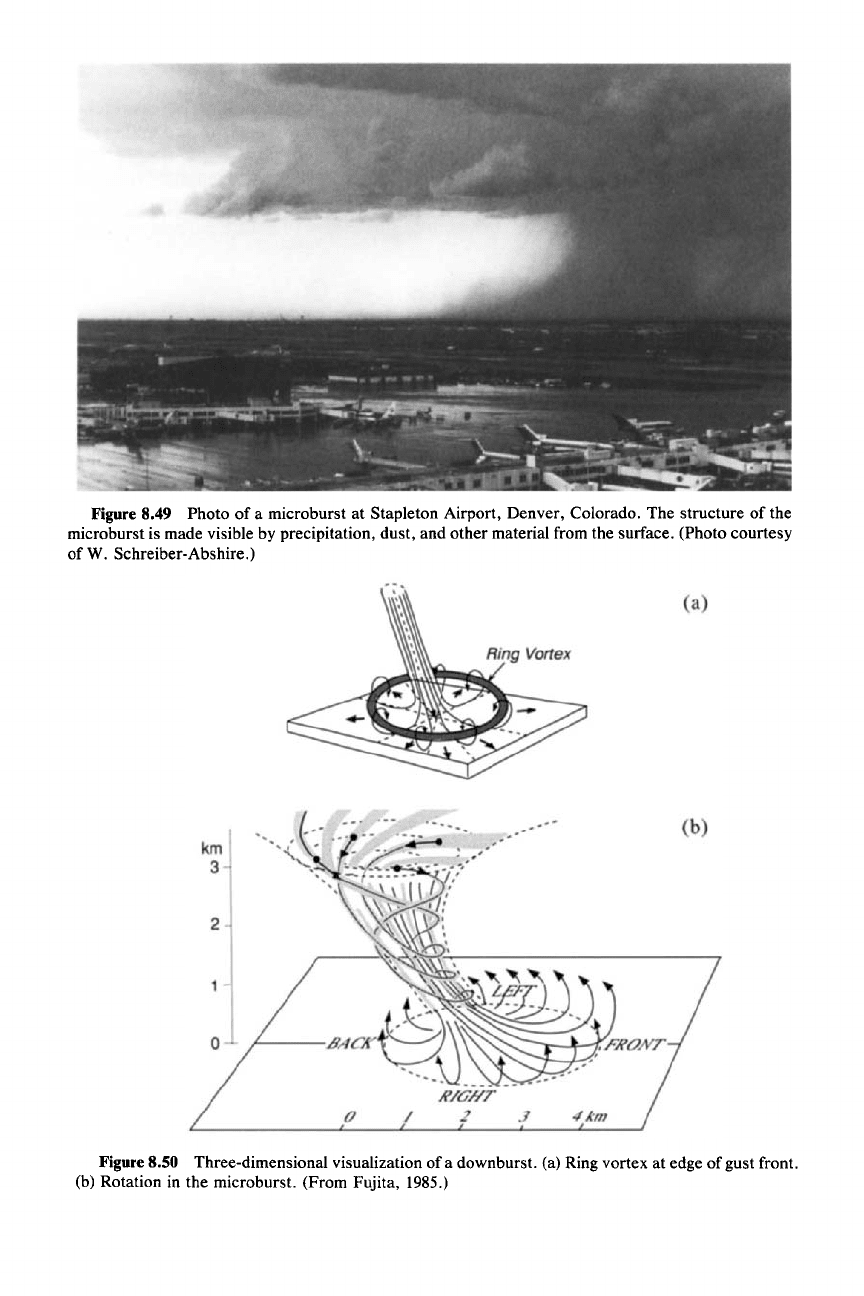
Figure 8.49 Photo of a microburst at Stapleton Airport, Denver, Colorado. The structure of the
microburst is made visible by precipitation, dust, and other material from the surface. (Photo courtesy
of W. Schreiber-Abshire.)
Figure 8.50 Three-dimensional visualization of a down burst. (a) Ring vortex at edge of gust front.
(b) Rotation in the microburst. (From Fujita, 1985.)
8.10 Downbursts 323
\\\\
~III
~tt~
Jowndfanl
Increasing I \ \\ \ \ \ Increasing
Headwind /
j J \ \ \ Tailwind
/ / ) \
-:
~
/2
/9f\
4
<,
Outflow
---
~
/
....
\.
__
Outflow
1".,/
"--_5
",,==--y
~
~
TI/IIlllII/7V!!ll/lIIT//ITII7l/lT//lTi//lIllllllm;Z
!iV1777717
r (1-3
km)------o-!
Figure 8.51 Idealization of an aircraft taking off through a microburst. After lifting off in an
increasing headwind at
1, the aircraft begins to lose the headwind and enter the downdraft at 2,
experiences stronger headwind loss at 3 with subsequent arrest of climb, begins descending in
increasing tailwind at 4, and experiences an accelerating descent rate through 5. (From Elmore et al.,
1986. Reprinted with permission from the American Meteorological Society.)
descent rate may be impossible to arrest before the plane crashes into the
ground.P"
8.10.3 Dynamics of Microbursts
Investigations of the dynamics of microbursts have focused on two main issues.
First, the mechanisms driving the downdraft have been sought. These mecha-
nisms turn out to be primarily microphysical and thermodynamical. We will exam-
ine these mechanisms in Sec. 8.10.3.1. The second issue concerns the dynamics of
the rotor circulation constituting the outward-propagating ring vortex, where the
strong surface winds are located. We will examine the rotor dynamics in Sec.
8.10.3.2.
8.10.3.1 Mechanisms Driving Microbursts
The mechanisms of downdraft acceleration are approached through examina-
tion of the vertical component of the equation of motion (2.47), which in the
absence of the frictional force may be written as
Dw 1
ap*
* *
Dt
=-
Po
az
+B(Ov,p
,qH)
(8.45)
where the dependence of the buoyancy B on the thermodynamic variables
(8:
,p*
.q«)
is given by (2.52). In a case study of downbursts observed by Doppler
236 This illustration is taken from Elmore et al. (1986).
324 8 Thunderstorms
radar.P? the terms on the right-hand side of (8.45) were estimated by performing
thermodynamic retrieval analysis of the type discussed in Sec.
4.4.7.
The pressure gradient acceleration in (8.45) was found to be small compared to
the buoyancy. This result could have been anticipated since the microburst is
characterized by a pressure maximum at the surface, which produces an upward-
directed pressure gradient force acting against the downdraft. The micro burst
problem thus reduces to understanding the negative contributions to
B. Doppler
radar data showed that the vertical acceleration [left-hand side of
(8.45)] in the
case study microburst was
-0.1
m
S-2.
The precipitation mixing ratio implied by
the observed radar reflectivity [Eq.
(4.12)] suggested that only about 20% of the
total acceleration was accounted for by precipitation drag [i.e., by the contribu-
tion of
r qn to B in (2.52)]. If the contribution of p* to
Bin
(2.52) is small, then 80%
of the negative buoyancy in the downburst must have been associated with
0:.
A
value of
0:
=
-2.5
K is thus implied. This value is consistent with values
of
0:
obtained by application of thermodynamic retrieval to the Doppler
radar-derived
flow field. If all the hydrometeors had been ice, melting could have accounted for
only
0:
=
-0.4
K. Thus, most
of
the cooling responsible for the negative buoy-
ancy of the downburst appears to have been brought on by evaporation of hydro-
meteors.
Radar evidence from
other
cases also suggests that microphysically induced
negative buoyancy is crucial to microburst generation. However, it suggests that
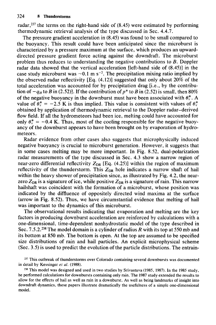
in some cases melting may be more important. In Fig.
8.52, dual-polarization
radar measurements of the type discussed in Sec.
4.3 show a narrow region of
near-zero differential reflectivity
ZOR
[Eq. (4.25)] within the region of maximum
reflectivity of the thunderstorm. This
ZOR
hole indicates a narrow shaft of hail
within the heavy shower
of
precipitation since, as illustrated by Fig. 4.2, the near-
zero
ZOR
is a signature
of
ice, while positive
ZOR
is a signature of rain. This narrow
hailshaft was coincident with the formation of a microburst, whose position was
indicated by the diffluence of oppositely directed wind maxima at the surface
(arrow in Fig.
8.52). Thus, we have circumstantial evidence that melting of hail
was important to the dynamics
of
this microburst.
The observational results indicating that evaporation and melting are the key
factors in producing downburst acceleration are reinforced by calculations with a
one-dimensional, time-dependent nonhydrostatic model of the type described in
Sec.
7.5.2.
238
The model domain is a cylinder of radius R with its top at 550 mb
and
its bottom at 850 mb. The bottom is open. At the top are assumed to be specified
size distributions of rain and hail particles. An explicit microphysical scheme
(Sec.
3.5) is used to predict the evolution
ofthe
particle distributions. The entrain-
237 This outbreak of thunderstorms
over
Colorado containing several downbursts was documented
in detail by Kessinger
et al. (1988).
238 This model was designed and used in two studies by Srivastava (1985, 1987). In the 1985 study,
he performed calculations for down bursts containing only rain. The 1987 study extended the results to
allow for the effects of hail as well as rain in a downburst. As well as being landmarks of insight into
downdraft dynamics, these papers illustrate dramatically the usefulness of a simple one-dimensional
model.
10
.-,
,
,
..........
..
-
.....
,
,
,
,
,
,
,
,
,
,
,
,
HORIZONTAL DISTANCE (km)
Figure 8.52 Vertical cross section
showing dual-polarization Doppler ra-
dar measurements obtained in a thun-
derstorm in northern Alabama. Reflec-
tivity data are presented in contours of
dBZ. Differential reflectivity
ZOR
are
shown in dB units. Arrow indicates lo-
cation of the center of a surface micro-
burst. (From Wakimoto and Bringi,
1988. Reprinted with permission from
the American Meteorological Society.)
,-.. 40
i >.
,I"
"'\,
I
\.
,
,,' " .." '\
, ,
, ,
, ,
, ,
. ,
,
..
REFLECTIVITY
(dBZ~8.7
25.5 29.5 34.2
39.6
46
51.7
10
-15
•
-8.4
•
I I
0.10
1.0
RAINWATER
MIXING
RATIO
(g
kc;fl
)
-0.24
-Q.8
-9.3
-13
• •
•
•
-3.8
-6.7
-9.5
8'"
-Q.2
-0.5
-1.7 -6.8
• • • •
-0.3
-0.5
-3.0
-7.5
•
-3.2
7L.---_.L-
.L...-
---I
RAINFALL
RATE
(mm
h")0.6
1.7
3.1
6.5
15.2
42
110
.
...
.
~
~
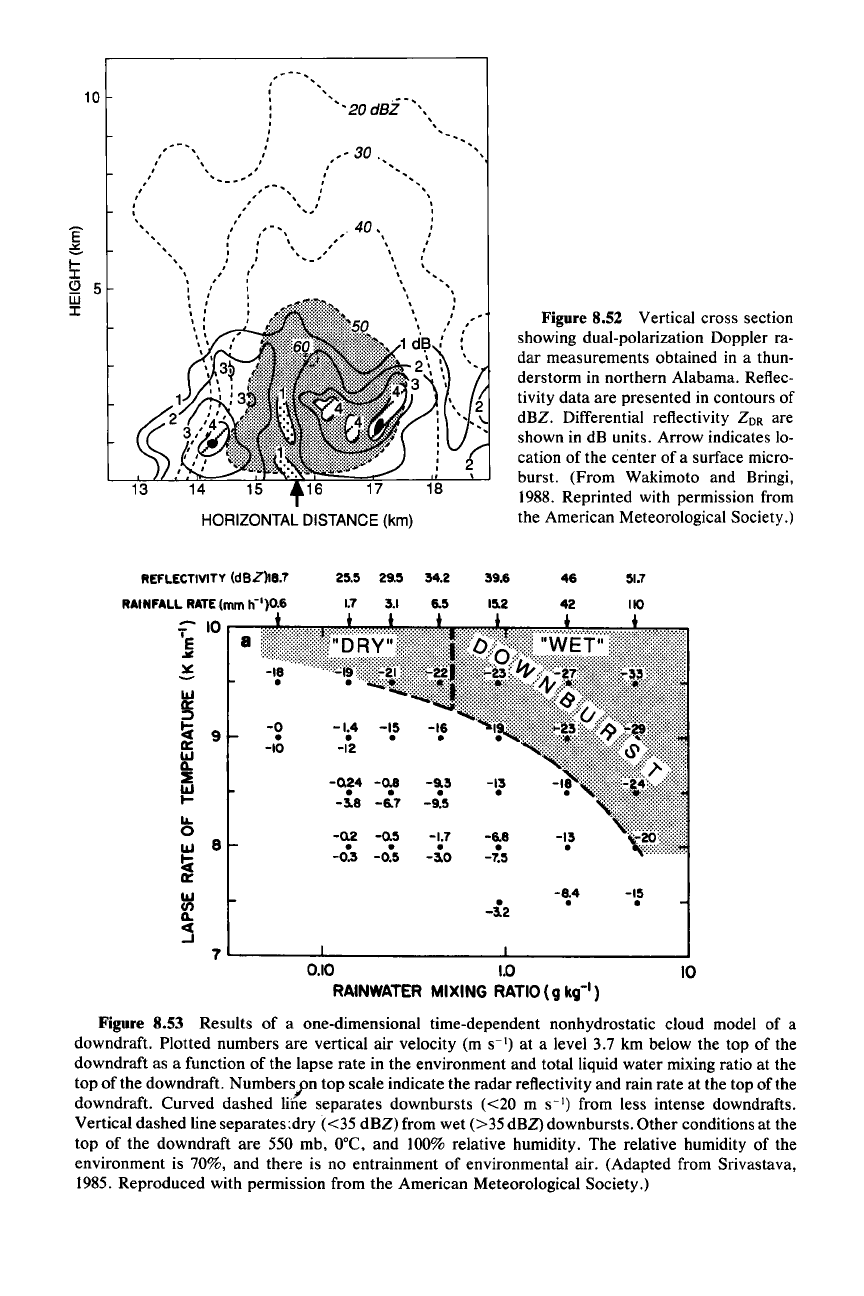
Figure 8.53 Results of a one-dimensional time-dependent nonhydrostatic cloud model of a
downdraft. Plotted numbers are vertical
air velocity (m
S-I)
at a level 3.7 km below the top of the
downdraft as a function of the lapse rate in the environment and total liquid water mixing ratio at the
top
ofthe
downdraft. Numbers;>n top scale indicate the radar reflectivity and rain rate at the top of the
downdraft. Curved dashed line separates downbursts
«20
m
S-I)
from less intense downdrafts.
Vertical dashed line separates:dry
«35
dBZ) from wet
(>
35dBZ) downbursts. Other conditions at the
top of the downdraft are 550 rnb,
O°C,
and 100% relative humidity. The relative humidity of the
environment is 70%, and there is no entrainment of environmental air. (Adapted from Srivastava,
1985. Reproduced with permission from the American Meteorological Society.)

326 8 Thunderstorms
ment rate is assumed to be inversely proportional to R [consistent with the contin-
uous entrainment models considered in Sec 7.3.2, e.g., (7.38), (7.46), (7.48)]. The
environmental lapse rate and humidity are specified. In calculations including only
raindrops in the water-continuity equations, the microphysical and environmental
conditions that produced downdrafts of
>20
m
S-1
in intensity were sought. Such
a strong downdraft was taken to be an indication of a downburst. Results for the
case of zero entrainment (achieved effectively at a radius of about
I km) and an
initial Marshall-Palmer distribution [Eq. (3.70)] ofraindrops falling into the top of
the domain are shown in Fig. 8.53. They indicate that downbursts are most readily
obtained as the lapse rate approaches the dry adiabatic (9.8°C krn
")
and as the
rainfall rate (or radar reflectivity) increases. Other results, not shown in the figure,
are that the tendency toward down burst occurrence increases with decreasing
mean raindrop size (since small drops evaporate more readily than large ones),
with a
less well-mixed boundary layer (in which relative humidity rather than
mixing ratio is assumed constant in the environment) and with
increased relative
humidity in the environment.
The
last two results are somewhat counterintuitive,
since microbursts often
occur
in dry and/or well-mixed boundary layers. How-
ever, the physics are clear. As the relative humidity (RH) of the environment is
increased for a given temperature profile, especially near the top of the downdraft
layer, buoyancy in the downdraft, measured relative to the environment, becomes
more strongly negative [i.e.,
q:
==
qv -
q.,
becomes more largely negative as RH
increases since
qv = qvAT), q.; =
RH·
qvs
(T
e),
and T < T
e].
The optimal condi-
tions for downburst formation in the absence of ice are then indicated to be an
environment close to dry adiabatic, with a high rainwater content near cloud base
and a minimum downdraft radius of I km. Note that there is no indication from
these calculations as to why the downburst should be small in scale.
When hail as well as rain is included in the precipitation falling into the top of
the model domain, calculations show that the additional negative buoyancy pro-
vided by melting can produce downbursts when the lapse rate is more stable than
dry adiabatic. At higher environmental stability, higher precipitation content in
the form of ice and relatively higher concentrations of small precipitation particles
are required to generate an intense downdraft. At lower environmental stability,
both dry and wet downbursts are possible. As the stability increases, only pro-
gressively wetter downbursts are possible. As the environment becomes even
more stable, only wet downbursts having substantial precipitation in the form of
ice are possible.
Numerical modeling of downbursts with a two-dimensional model
of
the type
discussed in Sec. 7.5.3 is consistent with the one-dimensional model results
just
described. In the example examined here.P? a bulk cold-cloud scheme (Sec. 3.6.2)
is used to represent microphysical processes in the water-continuity equations.
The model domain is 5 km deep and 10 km wide. Calculations are initiated by
prescribing a distribution of hail at the top boundary. Again, melting and evapora-
tion are both found to be important in driving the downdraft, with evaporation
239 From Proctor (1988).
8.10 Downbursts 327
being the stronger effect.
The
two-dimensional model provides additional insight
into the distribution of these processes in time and space. Melting is more impor-
tant in the earlier stages, with evaporation becoming dominant later and at lower
levels.
It
is also found that the downdraft is induced by precipitation drag with the
evaporation and melting becoming dominant subsequent to the initiation.
8.10.3.2
Rotor
Circulation
and
Outburst Winds
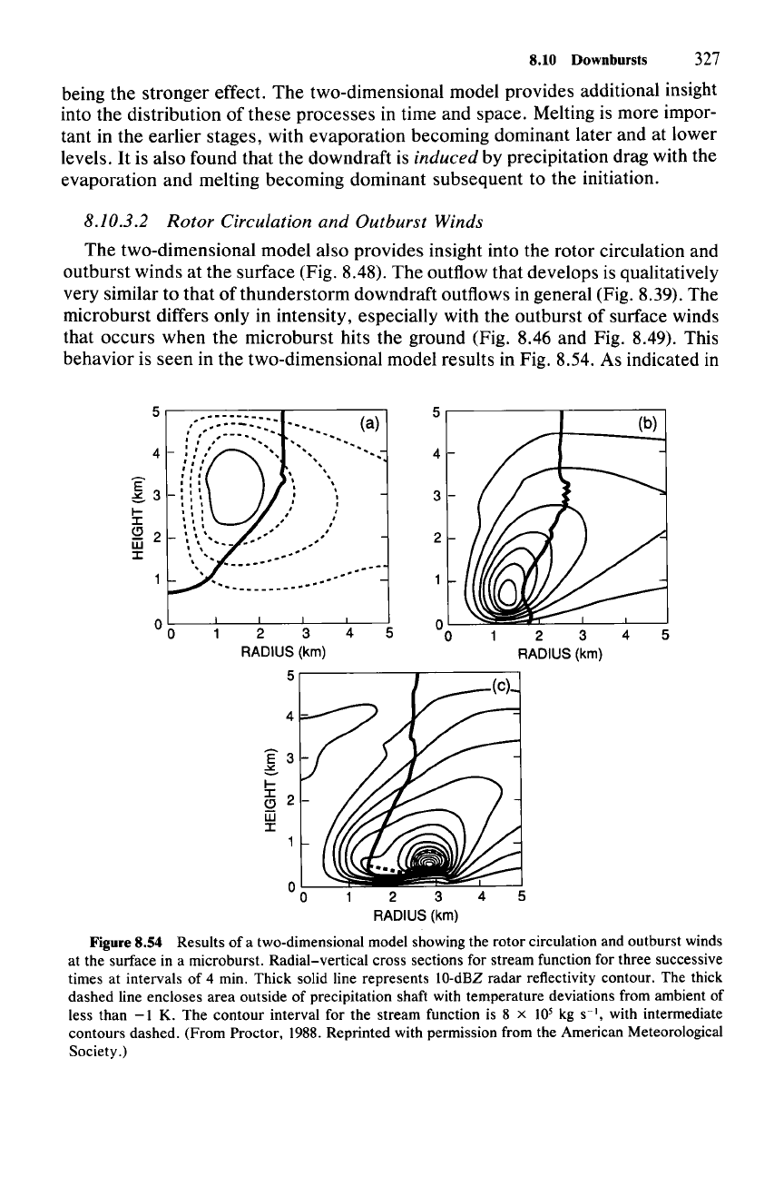
The two-dimensional model also provides insight into the rotor circulation and
outburst winds at the surface (Fig. 8.48). The outflow that develops is qualitatively
very similar to that
of
thunderstorm downdraft outflows in general (Fig. 8.39). The
microburst differs only in intensity, especially with the outburst of surface winds
that occurs when the microburst hits the ground (Fig. 8.46 and Fig. 8.49). This
behavior is seen in the two-dimensional model results in Fig. 8.54. As indicated in
5
(b)
2 3 4
RADIUS (km)
2
5
.------------,,.--------,
4
5
.--
..'
..'
..,
E
3-
C
I-
::I:
o
m
::I:
2 3 4
RADIUS (km)
5
.---------y----------,
5.--------=------r-----,
00
2 3 4
RADIUS (km)
Figure 8.54 Results of a two-dimensional model showing the rotor circulation and outburst winds
at the surface in a microburst. Radial-vertical cross sections for stream function for three successive
times at intervals of 4 min. Thick solid line represents 10-dBZ radar reflectivity contour. The thick
dashed line encloses area outside of precipitation shaft with temperature deviations from ambient of
less than
-I
K. The contour interval for the stream function is 8 x 10
5
kg
S-I.
with intermediate
contours dashed. (From Proctor, 1988. Reprinted with permission from the American Meteorological
Society.)
328 8 Thunderstorms
Figure 8.55
(a)
(b)
(c)
Figure 8.56
Stronger
than
before
