Hoffman D.M., Singh B., Thomas J.H. (Eds). Handbook of Vacuum Science and Technology
Подождите немного. Документ загружается.

432 Chapter 4.2: Flange and Component Systems
REFERENCES
1.
C. H. Rosendahl, Sheet Metal Industries (February 1970), pp. 93-109.
2.
R. D. Thomas, Jr., Welding Research Supplement to The Welding Journal (December 1984),
pp.
335s-368s.
3.
N. Suutala, T. Takalo, and T. Moisio, Metallurgical Transactions A, llA (1980) 717-725.
4.
SEMI standards E21-94 and E21.1-92, available from SEMI North America, 805 East Middle-
field Road, Mountain View, CA 94043, telephone (415) 964-5111, semihq@semi.org.
CHAPTER
4.3
Magnetic-FIuid-Sealed
Rotary Motion
Feedthroughs
Walter Helgeland
Rigaku/USA,
Inc
4.3.1
BASIC SEALING PRINCIPLE
In this class of rotary feedthroughs, dynamic sealing is accomplished by
a
hermetic
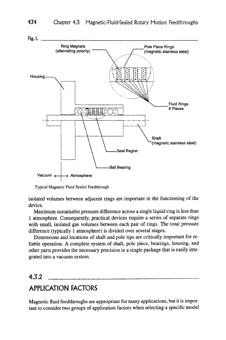
liquid seal that permits free rotation of the shaft. Figure 1 illustrates the arrange-
ment of the major elements in a typical device.
Magnetic fluids are stable colloids comprising a base liquid, ferromagnetic par-
ticles,
and a dispersing agent that suspends the particles in the base liquid. The
ferromagnetic particles interact directly with an external magnetic field. Because
of the strong coupling to the magnetic particles via the dispersing agent, the base
liquid interacts indirectly with the external magnetic field. Hence magnetic fluids
can be pushed, pulled, and shaped by magnetic fields. In feedthroughs, narrow
rings of fluid form liquid barriers filling the annular spaces between a rotating
shaft and the tips of a stationary pole piece. Radially, the fluid rings are bounded
by the shaft and the pole piece tips. Axially, the rings are free surfaces at gas-
liquid interfaces, restrained only by magnetic forces. Magnetic flux density at
the pole tips is very large. Hence, any axial displacement of a liquid ring from the
neighborhood of the pole tip results in a force that resists the displacement. The
ISBN 0-12-325065-7 Copyright © 1998 by Academic Press
^^^•^ All rights of reproduction in any form reserved.
433
434
Fig.l.
Chapter 4.3: Magnetic-Fluid-Sealed Rotary Motion Feedthrouglis
Ring Magnets
(alternating polarity)
Pole Piece Rings
(magnetic stainless steel)
Housing
Vacuum
Fluid Rings
8 Places
Shaft
(magnetic stainless steel)
Ball Bearing
Atmosphere
Typical Magnetic Fluid Sealed Feedthrough
isolated volumes between adjacent rings
are
important
in
the functioning
of
the
device.
Maximum sustainable pressure difference across a single liquid ring is less than
1 atmosphere. Consequently, practical devices require
a
series
of
separate rings
with small, isolated gas volumes between each pair
of
rings.
The
total pressure
difference (typically 1 atmosphere)
is
divided over several stages.
Dimensions and locations
of
shaft and pole tips are critically important for re-
liable operation.
A
complete system
of
shaft, pole piece, bearings, housing,
and
other parts provides the necessary precision in
a
single package that is easily inte-
grated into
a
vacuum system.
4.3.2
APPLICATION FACTORS
Magnetic fluid feedthroughs are appropriate for many applications, but it
is
impor-
tant to consider two groups
of
application factors when selecting
a
specific model
4.3.2 Application Factors
435
Rg.2.
1E+4
1E+3
1E+2
1E+1
1E+0
1E-1
Special designs for high pressure
Normal range of application
Vy^ter-cooling required only when operating
at very high speed
Water-cooling
advisable
40 50 60
Operating Temperature of Feedthrough ('C)
Operating Region Guidelines
for a particular application. Environmental factors always include process operat-
ing pressure and ambient temperature, and may include other process-related fac-
tors as
well.
Mechanical factors include speed, loads (radial and
thrust),
duty cycle,
and bearing ratings.
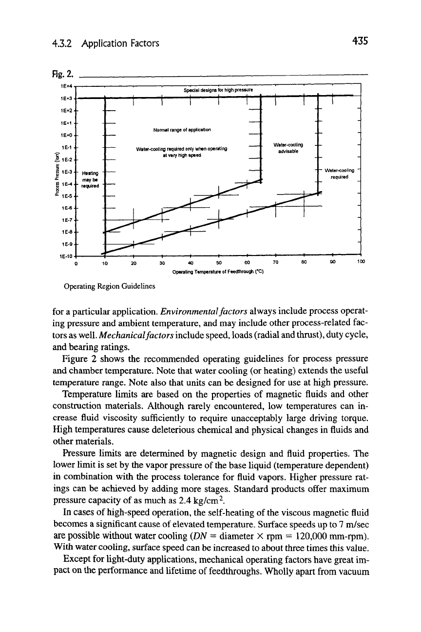
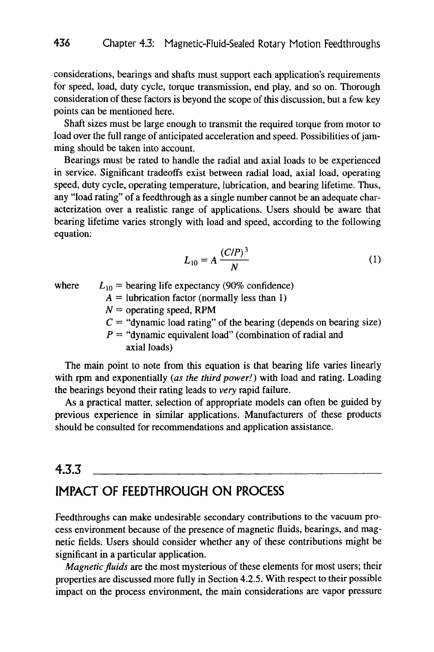
Figure 2 shows the recommended operating guidelines for process pressure
and chamber temperature. Note that water cooling (or heating) extends the useful
temperature range. Note also that units can be designed for use at high pressure.
Temperature limits are based on the properties of magnetic fluids and other
construction materials. Although rarely encountered, low temperatures can in-
crease fluid viscosity sufficiently to require unacceptably large driving torque.
High temperatures cause deleterious chemical and physical changes in fluids and
other materials.
Pressure limits are determined by magnetic design and fluid properties. The
lower limit is set by the vapor pressure of the base liquid (temperature dependent)
in combination with the process tolerance for fluid vapors. Higher pressure rat-
ings can be achieved by adding more stages. Standard products offer maximum
pressure capacity of as much as 2.4 kg/cm ^.
In cases of high-speed operation, the self-heating of the viscous magnetic fluid
becomes a significant cause of elevated temperature. Surface speeds up to 7 m/sec
are possible without water cooling {DN = diameter X rpm = 120,000 mm-rpm).
With water cooling, surface speed can be increased to about three times this value.
Except for light-duty applications, mechanical operating factors have great im-
pact on the performance and lifetime of feedthroughs. Wholly apart from vacuum
436 Chapter 4.3: Magnetic-Fluid-Sealed Rotary Motion Feedthroughs
considerations, bearings and shafts must support each application's requirements
for speed, load, duty cycle, torque transmission, end play, and so on. Thorough
consideration of these factors is beyond the scope of this discussion, but a few key
points can be mentioned here.
Shaft sizes must be large enough to transmit the required torque from motor to
load over the full range of anticipated acceleration and speed. Possibilities of jam-
ming should be taken into account.
Bearings must be rated to handle the radial and axial loads to be experienced
in service. Significant tradeoffs exist between radial load, axial load, operating
speed, duty cycle, operating temperature, lubrication, and bearing lifetime. Thus,
any "load rating" of
a
feedthrough as a single number cannot be an adequate char-
acterization over a realistic range of applications. Users should be aware that
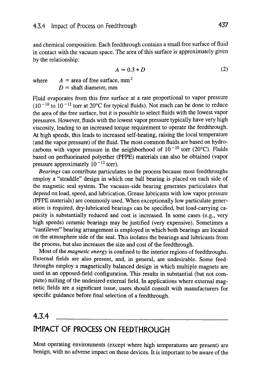
bearing lifetime varies strongly with load and speed, according to the following
equation:
Lio = A—^ (1)
where ^lo = bearing life expectancy (90% confidence)
A = lubrication factor (normally less than 1)
A^
= operating speed, RPM
C = "dynamic load rating" of the bearing (depends on bearing size)
P = "dynamic equivalent load" (combination of radial and
axial loads)
The main point to note from this equation is that bearing life varies linearly
with rpm and exponentially (as the third power!) with load and rating. Loading
the bearings beyond their rating leads to very rapid failure.
As a practical matter, selection of appropriate models can often be guided by
previous experience in similar applications. Manufacturers of these products
should be consulted for reconmiendations and application assistance.
4.3.3
IMPACT
OF
FEEDTHROUGH
ON
PROCESS
Feedthroughs can make undesirable secondary contributions to the vacuum pro-
cess environment because of the presence of magnetic fluids, bearings, and mag-
netic fields. Users should consider whether any of these contributions might be
significant in a particular application.
Magnetic fluids are the most mysterious of these elements for most users; their
properties are discussed more fully in Section
4.2.5.
With respect to their possible
impact on the process environment, the main considerations are vapor pressure
4.3.4 Impact of Process on Feedthrough 437
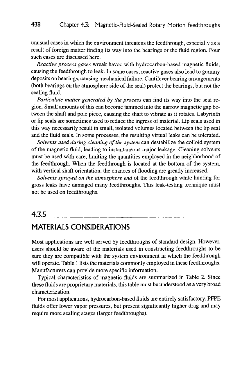
and chemical composition. Each feedthrough contains a small free surface of fluid
in contact with the vacuum space. The area of this surface is approximately given
by the relationship:
A =- 0.3 * D (2)
where A = area of free surface, mm^
D = shaft diameter, mm
Fluid evaporates from this free surface at a rate proportional to vapor pressure
(10"^^
to 10"^^ torr at 20°C for typical fluids). Not much can be done to reduce
the area of the free surface, but it is possible to select fluids with the lowest vapor
pressures. However, fluids with the lowest vapor pressure typically have very high
viscosity, leading to an increased torque requirement to operate the feedthrough.
At high speeds, this leads to increased self-heating, raising the local temperature
(and the vapor pressure) of
the
fluid. The most common fluids are based on hydro-
carbons with vapor pressure in the neighborhood of
10 "^^
torr (20°C). Fluids
based on perfluorinated polyether (PFPE) materials can also be obtained (vapor
pressure approximately 10"^^ torr).
Bearings can contribute particulates to the process because most feedthroughs
employ a "straddle" design in which one ball bearing is placed on each side of
the magnetic seal system. The vacuum-side bearing generates particulates that
depend on load, speed, and lubrication. Grease lubricants with low vapor pressure
(PFPE materials) are commonly used. When exceptionally low particulate gener-
ation is required, dry-lubricated bearings can be specified, but load-carrying ca-
pacity is substantially reduced and cost is increased. In some cases (e.g., very
high speeds) ceramic bearings may be justified (very expensive). Sometimes a
"cantilever" bearing arrangement is employed in which both bearings are located
on the atmosphere side of the seal. This isolates the bearings and lubricants from
the process, but also increases the size and cost of the feedthrough.
Most of the magnetic energy is confined to the interior regions of feedthroughs.
External fields are also present, and, in general, are undesirable. Some feed-
throughs employ a magnetically balanced design in which multiple magnets are
used in an opposed-field configuration. This results in substantial (but not com-
plete) nulling of the undesired external field. In applications where external mag-
netic fields are a significant issue, users should consult with manufacturers for
specific guidance before final selection of a feedthrough.
4.3.4
IMPACT OF PROCESS ON FEEDTHROUGH
Most operating environments (except where high temperatures are present) are
benign, with no adverse impact on these devices. It is important to be aware of the
438 Chapter 4.3: Magnetic-Fluid-Sealed Rotary Motion Feedthroughs
unusual cases in which the environment threatens the feedthrough, especially as a
result of foreign matter finding its way into the bearings or the fluid region. Four
such cases are discussed here.
Reactive process gases wreak havoc with hydrocarbon-based magnetic fluids,
causing the feedthrough to leak. In some cases, reactive gases also lead to gummy
deposits on bearings, causing mechanical failure. Cantilever bearing arrangements
(both bearings on the atmosphere side of the seal) protect the bearings, but not the
sealing fluid.
Particulate matter generated by the process can find its way into the seal re-
gion. Small amounts of
this
can become janmied into the narrow magnetic gap be-
tween the shaft and pole piece, causing the shaft to vibrate as it rotates. Labyrinth
or lip seals are sometimes used to reduce the ingress of
material.
Lip seals used in
this way necessarily result in small, isolated volumes located between the lip seal
and the fluid seals. In some processes, the resulting virtual leaks can be tolerated.
Solvents used during cleaning of the system can destabilize the colloid system
of the magnetic fluid, leading to instantaneous major leakage. Cleaning solvents
must be used with care, limiting the quantities employed in the neighborhood of
the feedthrough. When the feedthrough is located at the bottom of the system,
with vertical shaft orientation, the chances of flooding are greatly increased.
Solvents sprayed on the atmosphere end of the feedthrough while hunting for
gross leaks have damaged many feedthroughs. This leak-testing technique must
not be used on feedthroughs.
4.3.5
MATERIALS CONSIDERATIONS
Most applications are well served by feedthroughs of standard design. However,
users should be aware of the materials used in constructing feedthroughs to be
sure they are compatible with the system environment in which the feedthrough
will
operate.
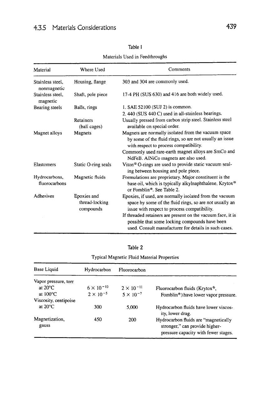
Table
1
lists the materials conmionly employed in these feedthroughs.
Manufacturers can provide more specific information.
Typical characteristics of magnetic fluids are sunmiarized in Table 2. Since
these fluids are proprietary materials, this table must be understood as a very broad
characterization.
For most applications, hydrocarbon-based fluids are entirely satisfactory. PFPE
fluids offer lower vapor pressures, but present significantly higher drag and may
require more sealing stages (larger feedthroughs).
4.3.5 Materials Considerations
439
Table 1
Materials Used in Feedthroughs
Material
Where Used
Comments
Housing, flange 303 and 304 are commonly used.
Shaft, pole piece 17-4 PH (SUS 630) and 416 are both widely used.
Balls,
rings 1. SAE 52100 (SUJ 2) is common.
2.
440 (SUS 440 C) used in all-stainless bearings.
Retainers Usually pressed from carbon strip steel. Stainless steel
(ball cages) available on special order.
Magnets Magnets are normally isolated from the vacuum space
by some of the fluid rings, so are not usually an issue
with respect to process compatibility.
Commonly used rare-earth magnet alloys are SmCo and
NdFeB.
AlNiCo magnets are also used.
Static
O-ring
seals Viton® 0-rings are used to provide static vacuum seal-
ing between housing and pole piece.
Magnetic fluids Formulations are proprietary. Major constituent is the
base oil, which is typically alkylnaphthalene, Krytox®
or Fomblin®. See Table 2.
Epoxies and Epoxies, if used, are normally isolated from the vacuum
thread-locking space by some of the fluid rings, so are not usually an
compounds issue with respect to process compatibility.
If threaded retainers are present on the vacuum face, it is
possible that some locking compounds have been
used. Consult manufacturer for details in such cases.
Stainless steel,
nonmagnetic
Stainless steel,
magnetic
Bearing steels
Magnet alloys
Elastomers
Hydrocarbons,
fluorocarbons
Adhesives
Table 2
Typical Magnetic Fluid Material Properties
Base Liquid
Hydrocarbon Fluorocarbon
Vapor pressure, torr
at 20°C
at 100°C
Viscosity, centipoise
at 20°C
Magnetization,
gauss
6X lO-'O
2X 10⁻⁵
300
450
2X 10""
5 X 10⁻⁷
5,000
200
Fluorocarbon fluids (Krytox®,
Fomblin®) have lower vapor pressure.
Hydrocarbon fluids have lower viscos-
ity, lower drag.
Hydrocarbon fluids are "magnetically
stronger," can provide higher-
pressure capacity with fewer stages.
440
Chapter 4.3: Magnetic-Fluid-Sealed Rotary Motion Feedthroughs
4.3.6
APPLICATION EXAMPLES
4.3.6.1 Light-Duty Feedthroughs
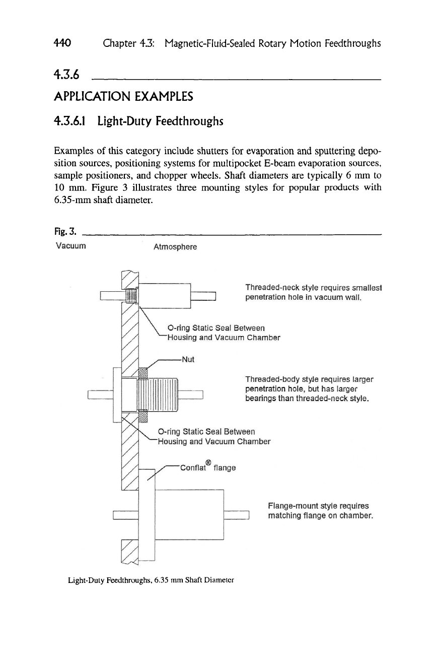
Examples of this category include shutters for evaporation and sputtering depo-
sition sources, positioning systems for multipocket E-bcam evaporation sources,
sample positioners, and chopper wheels. Shaft diameters are typically 6 mm to
10 mm. Figure 3 illustrates three mounting styles for popular products with
6.35-mm shaft diameter.
Rg.3.
Vacuum
Atmosphere
0-ring
Static Seal Between
Housing and Vacuum Chamber
Threaded-neck style requires smallest
penetration hole in vacuum
wall.
Threaded-body styJe requires larger
penetration hole, but has larger
bearings than threaded-neck style.
O-rlng
Static Seal Between
'Housing and Vacuum Chamber
Flange-mount style requires
matching flange on chamber.
Light-Duty Feedthroughs, 6.35 mm Shaft Diameter
4.3.6 Application Examples
441
Rg.4.
Magnetic Seal Section
Hollow Shaft
Static O-RIng
User Shaft
Clamp Secures Hollow Shaft
to User Shaft
Hollow Shaft Feedthrough
4.3,6.2 Hollow Shaft Seals
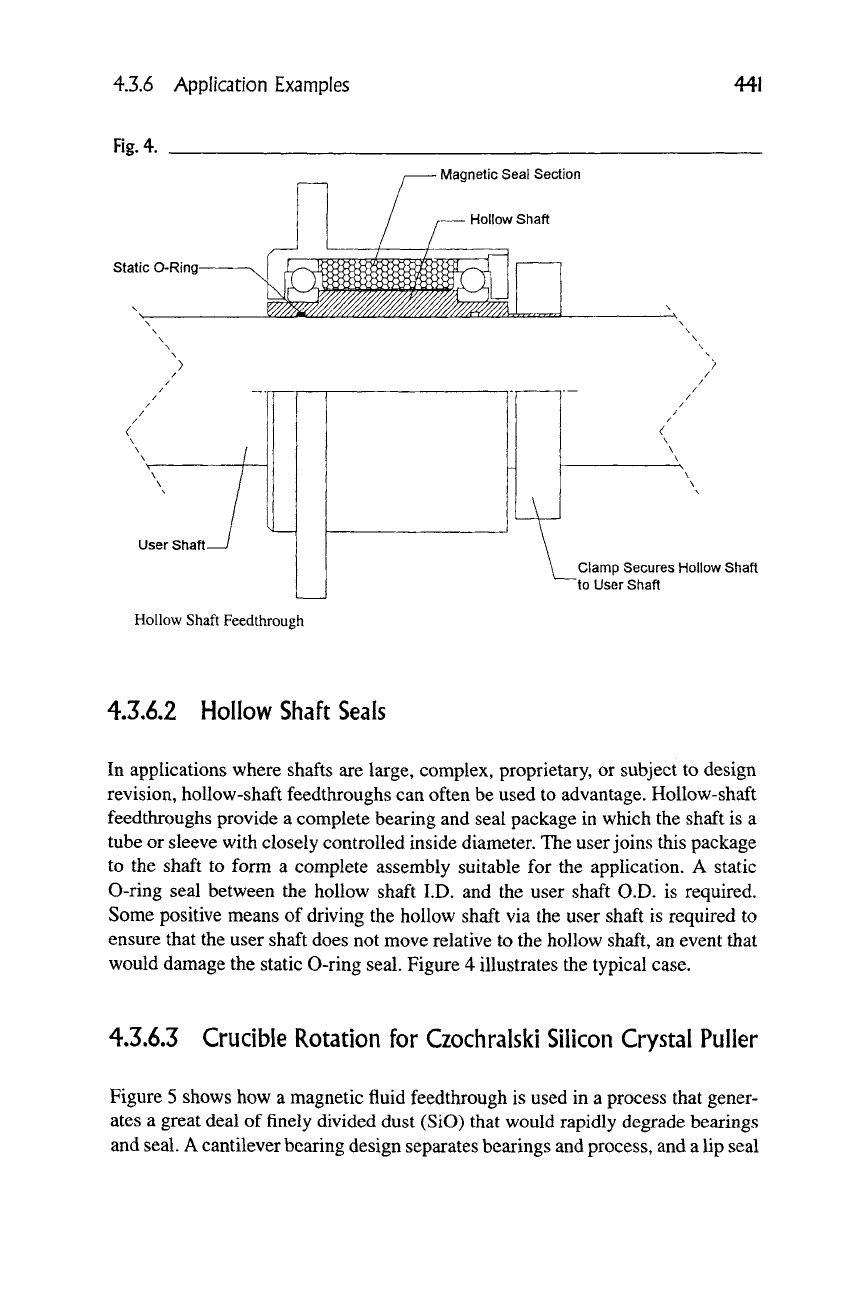
In applications where shafts are large, complex, proprietary,
or
subject
to
design
revision, hollow-shaft feedthroughs can often be used to advantage. Hollow-shaft
feedthroughs provide
a
complete bearing and seal package
in
which the shaft is
a
tube or sleeve with closely controlled inside diameter. The user joins this package
to
the
shaft
to
form
a
complete assembly suitable
for the
application.
A
static
0-ring seal between
the
hollow shaft I.D.
and the
user shaft O.D.
is
required.
Some positive means
of
driving the hollow shaft via the user shaft
is
required
to
ensure that the user shaft does not move relative to the hollow shaft, an event that
would damage the static 0-ring seal. Figure
4
illustrates the typical case.
4.3.6.3 Crucible Rotation
for
Czochralski Silicon Crystal Puller
Figure 5 shows how
a
magnetic fluid feedthrough is used in
a
process that gener-
ates
a
great deal
of
finely divided dust (SiO) that would rapidly degrade bearings
and seal. A cantilever bearing design separates bearings and process, and a lip seal
