Hoffman D.M., Singh B., Thomas J.H. (Eds). Handbook of Vacuum Science and Technology
Подождите немного. Документ загружается.

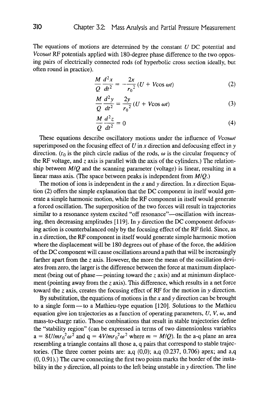
M d^x
'Q~dt^~
'Q~di^~
M d^z
'a'dt^'
2x
^0^
{U
H-
Vcos
(Ot)
-^{U-^
Vcos (ot)
0
310 Chapter 3.2: Mass Analysis and Partial Pressure Measurement
The equations of motions are determined by the constant U DC potential and
Vcosojt
RP potentials applied with 180-degree phase difference to the two oppos-
ing pairs of electrically connected rods (of hyperbolic cross section ideally, but
often round in practice).
(2)
(3)
(4)
These equations describe oscillatory motions under the influence of Vcosiot
superimposed on the focusing effect of Urn x direction and defocusing effect in y
direction, (ro is the pitch circle radius of the rods,
(o
is the circular frequency of
the RP voltage, and z axis is parallel with the axis of the cylinders.) The relation-
ship between M/Q and the scanning parameter (voltage) is linear, resulting in a
linear mass axis. (The space between peaks is independent from M/Q.)
The motion of ions is independent in the x and y direction. In x direction Equa-
tion (2) offers the simple explanation that the DC component in itself would gen-
erate a simple harmonic motion, while the RF component in itself would generate
a forced oscillation. The superposition of the two forces will result in trajectories
similar to a resonance system excited "off resonance"—oscillation with increas-
ing, then decreasing amplitudes
[119].
In j direction the DC component defocus-
ing action is counterbalanced only by the focusing effect of the RP field. Since, as
in
X
direction, the RP component in itself would generate simple harmonic motion
where the displacement will be 180 degrees out of phase of the force, the addition
of the DC component will cause oscillations around
a
path that will be increasingly
farther apart from the z axis. However, the more the mean of the oscillation devi-
ates from zero, the larger is the difference between the force at maximum displace-
ment (being out of phase—pointing toward the z axis) and at minimum displace-
ment (pointing away from the z axis). This difference, which results in a net force
toward the z axis, creates the focusing effect of RP for the motion in y direction.
By substitution, the equations of motions in the x and y direction can be brought
to a single form—to a Mathieu-type equation
[120].
Solutions to the Mathieu
equation give ion trajectories as a function of operating parameters, U, V, to, and
mass-to-charge ratio. Those combinations that result in stable trajectories define
the "stability region" (can be expressed in terms of two dimensionless variables
a = WlmrQ-o)'^ and q =
AVImrQ-o)'^
where m = M/Q). In the a-q plane an area
resembling a triangle contains all those a, q pairs that correspond to stable trajec-
tories.
(The three comer points are: a,q (0,0); a,q (0.237,
0.706)
apex; and a,q
(0,
0.91).)
The curve connecting the first two points marks the border of the insta-
bility in the y direction, all points to the left being unstable in y direction. The line
3.2.4 Ion Separation and Analyzers
311
connecting the last two points marks the border of the x instability region, all
points to the right being unstable in x direction. At the apex of the triangle only
one mass number (m) have stable trajectories (infinite resolution), while on a line
segment within the triangle a range of mass numbers are "stable." The high end
of this mass range is called "high pass critical mass," ions with higher mass num-
ber will have unstable trajectories in the y direction. Ions with lower mass number
than the "low pass critical mass" will have unstable trajectories in the x direction
[121].
Examples of ion trajectories and the a-q stability chart has been published
in an earlier volume
[122].
Instead of the a-q stability chart, we will discuss sta-
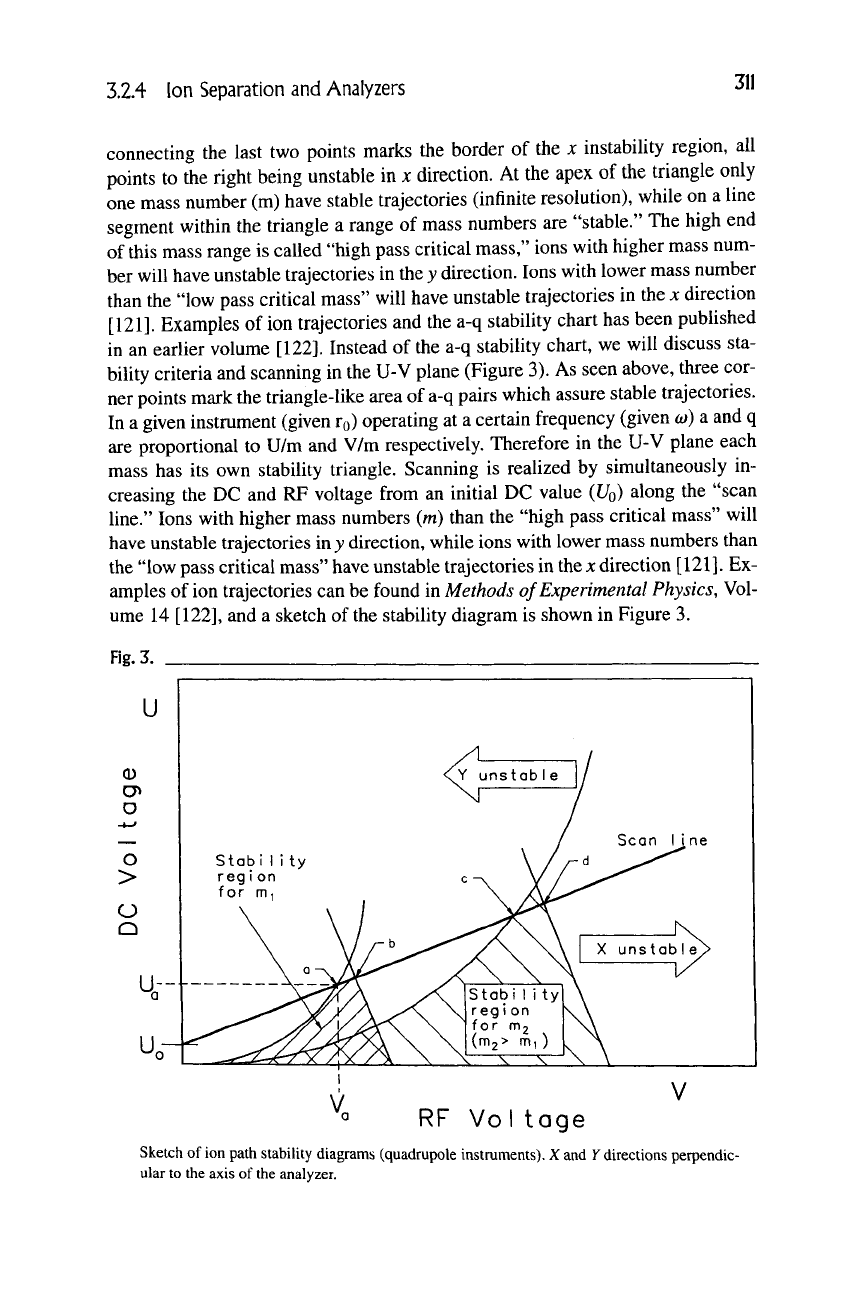
bility criteria and scanning in the U-V plane (Figure 3). As seen above, three cor-
ner points mark the triangle-like area of a-q pairs which assure stable trajectories.
In a given instrument (given ro) operating at a certain frequency (given
(D)
a and q
are proportional to U/m and V/m respectively. Therefore in the U-V plane each
mass has its own stability triangle. Scanning is realized by simultaneously in-
creasing the DC and RF voltage from an initial DC value
{UQ)
along the "scan
line."
Ions with higher mass numbers (m) than the "high pass critical mass" will
have unstable trajectories in y direction, while ions with lower mass numbers than
the "low pass critical mass" have unstable trajectories in
the
x direction
[121].
Ex-
amples of ion trajectories can be found in Methods of Experimental Physics, Vol-
ume 14
[122],
and a sketch of the stability diagram is shown in Figure 3.
Fig.
3.
U
RF Voltoge
Sketch of ion path stability diagrams (quadrupole instruments). X and
K
directions perpendic-
ular to the axis of the analyzer.
312 Chapter 3.2: Mass Analysis and Partial Pressure Measurement
Point a in Figure 3 on the scan line corresponds to the
U^
and
V^
pair where
ions of mass to charge ratio equal to
m
|
become stable not only in x direction but
also in y direction. Ions of higher mass number are unstable in y direction, as
shown by the "7unstable" curve of
m2
(nii > mi), which crosses the scan line at
point c. Ions of much lower mass number than
m
i
are unstable in x direction. The
"x unstable line" for mass m^ crosses the scan line at point 6, while for m2 it
crosses at point d. For the
U^,
V^
voltage pair the
"JC
unstable" line would cross the
scan line for a somewhat lower mass than nii at point a. (This mass number will
be called
Wi
— Am.) It means that ions with mass number higher than m\ -Am but
lower than
m
i
would exhibit stable trajectories both in x direction and y direction
when the voltage pair
Ur^,
V^
is selected. The width of this window. Am, is clearly
related to the slope of the scan
line
—
at
close to the tip of the stability regions the
bandwidth of the filter will be narrow.
If U and V are increased simultaneously along the scan line, eventually point b
is reached. It is the point where the x trajectories of ions of mass
m
i
become un-
stable. The y unstable line for a somewhat higher mass number (mi -hAw/) would
cross the scan line at the same point b. Therefore, as U and V are increased simul-
taneously along the scan line, a mass window of width Am is moved from lower
mass numbers to higher mass numbers (scanning).
The overall result is that the RF field without the DC component will create a
"high pass" filter that allows ions above a critical M/Q ratio to pass while the
addition of the DC component will create a "low pass" filter. The magnitude of
the DC voltage determines the "low pass" critical mass — if it is lower than
the "high pass" critical mass, no ions can reach the detector; if it is higher than the
"high pass" critical mass, a window is created.
Mass scan is accomplished by moving the "window" (Am) by changing the
amplitude of the RF (and the magnitude of the DC) voltage. When DC/RF ratio is
low (<0.1), the width of the window is large, resulting in low resolution. When
increasing the DC/RF ratio, the resolution increases on the expense of the trans-
mission efficacy. If DC/RF ratio approaches about 0.168, the apex of the stability
region is reached where the transmission drops to zero at infinitely high resolving
power. Experimentally this critical DC/RF ratio has been found to depend weakly
on the excitation frequency
[123].
The excitation frequency,
(o,
also affects the ul-
timate obtainable resolving power (M/iiM 2-3 times higher at 1.66 MHz than at
0.87 MHz).
While the resolving power will change as the mass number is varied in a typi-
cal instrument, two special cases can be identified. If the DC/RF ratio is kept con-
stant along the mass sweep (U/V independent from M/Q), then this represents a
"constant resolving power mode" of operation (constant
MIHsM).
In this case the
peak width will be proprtional to the mass number—resulting in narrow peaks at
low masses and wider peaks at high masses. Another special case is when the
DC/RF ratio is varied as the mass number is increased in such a way that the width
of the peak (AM) is kept constant. This is referred to as the "constant peak width
3.2.4 Ion Separation and Analyzers 313
mode" of operation. The resolving power {MI\M) will be consequendy propor-
tional to the mass number.
In practice the magnitude of an "offset" DC voltage (L'i), "resolution low") and
the magnitude of the slope of the DC/RF function (approximately UIV at high
masses, "resolution high") can be varied separately to adjust resolution at low and
high MIQ. The magnitude of the RF and DC voltage is increased to shift the
"window" along the mass scale from low MIQ toward high MIQ. A convenient
and often attempted setup is to keep the peak width (AM) more or less constant
along the entire mass range. A so-called integral spectrum is obtained easily by
switching off
the
DC component and allowing all ions above MIQ to reach the de-
tector as RF {V) is swept and the spectrum is recorded. As Equation (4) shows,
the initial axial velocity remains unchanged in the quadrupole field.
Besides the so-called first-stability regions shown on Figure 3, there are several
more predicted by theory as the F-unstable and X-unstable curves cross each other
again. These are of limited practical value due to decreased transmission and
usable mass range, but some applications may benefit from the much improved
abundance sensitivity (such as sepaiating He from D2) [124,1251.
Even though commercial instruments have been marketed using the ideal hy-
perbolic cross section electrodes (Pt-coated ceramics)
[126],
the majority of prac-
tical analyzers employ metal rods of circular cross section. The benefit of hyper-
bolical, coated ceramic electrodes is not only the more perfect quadrupole field
but rather the ability to produce partial pressure information at elevated tempera-
tures up to 400°C (750°F). Operating the analyzer at elevated temperatures is help-
ful when quantitative measurement of adsorbing components such as moisture is
attempted
[127].
The optimum radius for cylindrical electrodes has been deter-
mined theoretically (r = 1.148
TQ)
[128].
The effect of replacing the hyperbolic
cross section with a circular cross section has been studied extensively. The equa-
tion of motion includes terms reflecting coupling of the x and y fields. This results
in a "blunted tip" and a slight shift to the right of the stability diagram, limiting
the theoretically achieved maximum resolution [129,130]. The effect of the ra-
dius of the electrode relative to the optimum is important because of the increase
in the required driving power to achieve the same resolving power and sensitivity
(a factor of two, if r/ro is 1% higher than optimum at M/AM=400). At constant
driving power, the result is lower resolving power and sensitivity
[129].
Although
hyperbolic rods exceed round rods in performance (maximum achievable resolv-
ing power), increased driving frequency can make up for the difference (round
rod quadrupole driven at 1.7 MHz performs similarly to a same-size hyperbolic
driven at 0.7 MHz)
[131].
The sharp decrease in sensitivity of quadrupoles with
circular rods at a resolving power lower than a quadrupole with hyperbolic rods is
primarily due to the decrease in the effective instrument radius. The perturbations
in the electric fields caused by the circular shapes limit the maximum excursion
of the oscillating ions from the z axis to a radius significantly smaller than
TQ.
The transmission efficacy—which is the ratio of current collected to that en-
314
Chapter 3.2: Mass Analysis and Partial Pressure Measurement
tering the quadrupole can be found by measuring the step corresponding to the
selected mass number in integral mode (DC off) and standard mode (DC on)
when using a conventional ion source. Plotting the transmission against the DC/
RF ratio (which determines the resolving power) one will typically find transmis-
sion exceeding 80% up to about 0.9 times the DC/RF ratio corresponding to the
apex of the stability diagram (about DC/RF=0.168)
[123].
(Transmission was
measured as a ratio of the ion current collected
vs.
the current entering the quadru-
pole at a given MIQ. The step in the "AC only" or total pressure mode was used
as a measure of the current entering the filter. Overall transmission of the system,
i.e., the ratio of ions collected to ions generated in the source (for a given MIQ
when the filter is tuned to this M/Q), is typically
10~
^
-10~^.) Using a narrow ion
beam, well-defined energy source movable under vacuum (such as an alkali ion
source Na"^,
K"*",
etc.) enables one to measure the transmission efficacy as a func-
tion of initial displacement, direction and velocity
[132].
From these measure-
ments empirical transmission laws [133] and the acceptance eUipses of a particu-
lar quadrupole configuration can be derived.
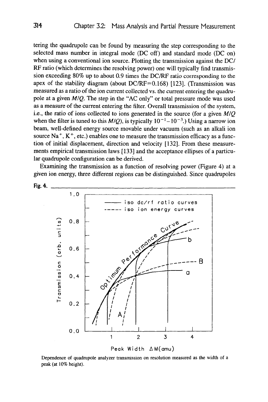
Examining the transmission as a function of resolving power (Figure 4) at a
given ion energy, three different regions can be distinguished. Since quadrupoles
Fig.
4.
J3
I-
o
(0
CO
c
o
1
.0
0.8
0.6
h
0.4
0.2
0.0
iso
dc/rf ratio curves
iso
Ion
energy curves
Peak Width AM(amu)
Dependence of quadrupole analyzer transmission on resolution measured as the width of a
peak (at
10%
height).
3.2.4 Ion Separation and Analyzers 315
in practice most often operate in constant peak width rather than in constant reso-
lution mode, in the following discussion we use peak width as a measure of reso-
lution. (Note that peak width increases as resolving power decreases.)
If at a given ion energy setting the resolution is low (peak width high), the
transmission will be found to be practically a slow function of resolution (such as
the quasi-horizontal part of line B on Figure
4).
This is the "source-limited" mode
of operation; the acceptance of the analyzer approaches or exceeds the emittance
of the source. Stability and reproducibility are determined primarily by changes
in the source. Transmission typically increases with initial velocity of ions (ion
energy) due to the fringing fields effects (see section on "coupling of the ionizer
to the analyzer," later). The peaks are "flat-topped" — trapezoidal.
Increasing the resolution (decrease in peak width) will take us to the region
where the acceptance of the analyzer will be considerably smaller than the emit-
tance of the source. This is the "analyzer limited" mode of operation, where the
transmission efficiency will be strongly dependent on the entrance conditions.
The latter is primarily due to the transient momentum impulse the ions receive
at the entrance of the analyzer characterized by imperfect and highly complex
quadrupole fields. It is well established that fringing fields introduce a depen-
dence of the acceptance on axial ion velocity. In the fringing fields, ions are stable
in the xz plane but unstable in the yz plane [134,135]. Combined acceptances
{xz and yz planes) are at the maximum at axial velocities where the ions spend
about two cycles in the fringing fields, and it falls off sharply for slower ions.
(Combined acceptance decreases by a factor of 10 if the time spent in the fringing
fields increases to four cycles [135].) This effect shows up as a decrease in sensi-
tivity with decreasing ion energy at a given resolution for a given mass or as mass
discrimination for ions injected at constant ion energy. (Heavier ions are slower
at constant ion energy, resulting in lower transmission as they spend more time
in the fringing fields.) Transmission in the "analyzer-limited" mode of operation
will be inversely proportional to the square of resolving power as a general rule.
Peak shape is triangular. (Between 0.7 and 1.5 Am on line B.)
Further increase in resolution at the same ion energy will result in very sharp
decrease in transmission, indicating that the "length" limited mode of operation is
reached. Here the analyzer is increasingly unable to distinguish an ion with stable
trajectory from an ion with unstable trajectory, which is related to the number of
RF cycles the ion takes to pass through
[135].
Peaks are sharp, triangular but their
height decreases much more rapidly than their width as resolution is increased.
If these transmission-resolution (or peak width) curves are taken at all pos-
sible ion energies, the resulting envelope of all these curves defines the optimum
performance curve. This curve connects the points corresponding to the highest
possible transmission (or sensitivity) at each resolution (or peak width). Note that
a different pair of DC/RF ratio and ion energy setting will realize maximum sen-
sitivity at each resolution. Even though operating on this curve provides the max-
imum performance, in some cases it may be justifiable to operate below this curve
316 Chapter 3.2: Mass Analysis and Partial Pressure Measurement
(such as in a source-limited mode to avoid that change in DC/RP ratio affects
peak height.) The falloff of this optimum performance curve for a particular ana-
lyzer represents the limitations of the instrument
itself.
Factors that determine the
maximum attainable resolution (besides finite length) are imperfections such as
circular rods instead of hyperbolic, deviations from the perfect symmetrical geom-
etry (displacement of
rods,
mechanical distortions due to baking), contamination
of surfaces, surface charges
[136].
Alignment of the ion source, imbalance of
electric fields (DC/RF ratio) and spurious ripple superimposed on the RF can all
be further limiting factors.
A further aspect of looking at transmission as a function of resolution is that
only the points along the optimum performance curve are defined by a unique
pair of ion energy and DC/RF ratio. All other transmission-resolution combina-
tions below that can be realized by two pairs of ion energy DC/RF setting. One
pair will be closer to the "source limited mode" (such as the intersection of lines
b and B on Figure 4), while the other will be closer to the "length-limited" mode
(such as the intersection of lines a and A). This is the result of the fact that both
transmission and resolution are functions of the two variables: ion energy and
DC/RF setting, thus defining two surfaces. The intersection of these two surfaces
is the curve called the "optimum performance curve."
The optimum performance curve is not independent of mass-to-charge ratio.
Since ions of higher masses spend longer time in the analyzer (at the same ion en-
ergy),
the length-limited region will shift toward the left (if peak width is used as
a measure of resolution—higher resolving power, i.e., lower Am). On the other
hand, high mass ions will spend more time in the fringing fields also, resulting in
a downward shift of the source-limited region. The overall effect is that the opti-
mum performance curve shifts to the left and downward as mass-to-charge ratio
increased.
Coupling of
the
ionizer to the analyzer is an important topic especially in the
case of quadrupole mass filters. If the substance to be analyzed fills the ionization
chamber volume uniformly and is in thermal equilibrium with the walls, ions are
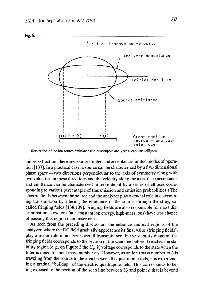
created in the space determined by the ionizing beam. Consider first the much
simpler one-dimensional case, where ions are generated along a line between two
points determined by the width of
the
ionizing beam (Figure
5).
Plotting the trans-
verse initial velocity of the ions exiting the source against their location results in
an ellipse that contains all the possible combinations. This is the emittance of the
source (phase space) at the exit. On the other hand, the analyzer will accept ions
depending on the position as well as transverse initial velocity of the ions. The el-
lipse that shows ions of what initial conditions will pass the analyzer is called the
acceptance
ellipse.
(This ellipse represents the upper boundary for initial velocity/
initial displacement combinations in the phase space that enables an ion to pass
the analyzer tuned to its particular MIQ ratio.) The overlap of these two ellipses
is the extraction. Depending on which ellipse is smaller, and so which one deter-
3.2.4
Ion
Separation
and
Analyzers
317
Fig.
5.
nitial transverse velocity
Analyzer acceptance
nitial pes
i
t
i
on
Source emittance
Cross section
source
-
analyzer
i
nterface
Illustration of the ion source emittance and quadrupole analyzer acceptance ellipses.
mines extraction, there are source-limited and acceptance-limited modes of opera-
tion
[137].
In a practical case, a source can be characterized by a five-dimensional
phase space—two directions perpendicular to the axis of symmetry along with
two velocities in these directions and the velocity along the axis. (The acceptance
and emittance can be characterized in more detail by a series of ellipses corre-
sponding to various percentages of transmission and emission probabilities.) The
electric fields between the source and the analyzer play a crucial role in determin-
ing transmission by altering the emittance of the source through the stray, so-
called fringing fields [138,139]. Fringing fields are also responsible for mass dis-
crimination; slow ions (at a constant ion energy, high-mass ions) have less chance
of passing this region than faster ones.
As seen from the preceding discussion, the entrance and exit regions of the
analyzer, where the DC field gradually approaches its final value (fringing fields),
play a major role in analyzer overall transmittance. In the stability diagram, the
fringing fields corresponds to the section of the scan line before it reaches the sta-
bility region (e.g., on Figure 3 the
U^,
V^
voltage corresponds to the state when the
filter is tuned to about mass number mj. However, as an ion (mass number mi) is
traveling from the source to the area between the quadrupole rods, it is experienc-
ing a gradual "buildup" of the electric quadrupole field. This corresponds to be-
ing exposed to the portion of the scan line between
U^
and point a that is beyond
318 Chapter 3.2: Mass Analysis and Partial Pressure Measurement
the stability region for an ion of mass number
m
i.) As a result, the ion trajectories
are unstable leading to high losses. A way to avoid this is to "bend" the scan line
so that it lies entirely within the stability region. This means that RF has to be in-
creased first, DC following only later on. This is called the "delayed DC ramp"
[140],
which can be realized by using a set of four additional electrodes between
the source and analyzer (and possibly also between the analyzer and detector)
driven by RF only. Several commercial partial pressure analyzers apply this
technique.
Variations of the quadrupole analyzer from its standard version as described
earlier can be grouped as variations in the driving voltage and variations in the
geometry of the filter.
A possible way to avoid losses and mass discrimination of high masses associ-
ated with fringing fields is not to use DC voltage at all. This so-called AC-only
mode of a quadrupole is essentially a high-pass filter, providing an integral spec-
trum. To obtain a regular spectrum, a "retarding field" or energy filter is applied
at the exit of the analyzer, which works based on the observation that ions that are
close to the border of the stability region (corresponding to the step in integral
mode) tend to be defocused, filling the aperture at the exit. Since the fringing
fields (from the RF) increase in field strength as the displacement from the z axis
increases, these ions gain more energy from the fields than others
[141].
A further
clear advantage is the elimination of the need to keep a constant DC/RF ratio. In-
deed, instruments with low mechanical tolerances behave in a superior way in this
mode of operation, but there is little difference if the instruments have been man-
ufactured accurately. Disadvantages are the difficulties at low M/Q (below 20)
and high-ion energy (above 4eV) related to the increased number of RF cycles an
ion must spend in the filter to obtain the same resolution as compared with the case
where the focusing/defocusing action of DC voltage is also present [142,143,144].
The removal of stringent control of DC/RF ratio can alternatively be achieved
by driving the rods with a rectangularly time-varying voltage waveform
[145],
with the promise of better stability, but this variation has not yet been adapted in
commercial instruments.
Variations in
thQ
filter
geometry have been investigated, such as concave shaped
[146],
flat electrodes
[147],
coated ceramics
[148],
and electrodes made of
(4
X 3)
wires to approximate quadrupole fields or to eliminate higher-order terms
[149].
All these are still using functionally four electrodes.
It has been recognized very early (1963) [150] that it is not necessary to use
four electrodes to employ the mass analyzer properties of quadrupole fields and
Equations (2) to (4). The combination of one circular (or hyperbolic) and a V-
shaped electrode (the circular rod being in the 90-degree opening of the V) can
simulate a quarter of the quadrupole field. This arrangement is the ''monopole''
mass spectrometer that has also been manufactured commercially. Other propos-
als—which have not been commercialized—are the ''dipole'' mass spectrometer
composed of two circular rods on one side of a plate electrode creating
"half"
a
3.2.4 Ion Separation and Analyzers
319
quadrupole field
[151].
A theoretical investigation of'multipole'' devices (hexa-
pole,
octapole) as a generalization of the geometry of the quadrupole has already
been carried out
[152];
and some of the geometries and means to realize it (such
as shaped glass) are patented.
Shorter but higher number of rods open up the way to increase the maximum
allowable operating pressure. Since the mean free path is inversely proportional
to the pressure, ion molecule collisions will affect linearity above 10"^ ton*
(~10"-^ Pa) (see Section 3.2.1.2). Shorter rods reduce ion-molecule collisions,
but in order to maintain resolution the frequency of the RF voltage has to be in-
creased. (Resolution is related to the number of cycles the ions spend in the
quadrupole field.) Using the same range of U and V (limited by arcouts) the pitch
circle radius of the rods (ro) has to be decreased proportionally to the increase
in
0).
(See Section 3.2.4.1 The variables defining the stability region —
a
and q—
are function of the product of
ro
and
co).
The smaller ro in turn will reduce the ac-
ceptance area of the analyzer which can be offset by using an array of quadru-
poles acting parallel. A practical device using a 3X3 quadrupole array (16 rods
forming 9 quadrupole analyzers) has been described
[153].
While the smaller size
of the analyzer head and the higher operating pressure limit are clear advantages,
resolution overall and power required to drive the analyzer are less favorable than
in the case of regular quadrupoles.
If the cross section of the quadrupole (four circles or hyperbolae) is rotated
around an axis passing through the center of a pair of opposing rods (e.g., the
X
axis) a ring and two end-caps are formed. This structure is a "three dimensional
quadrupole" or the quadrupole ion trap. The electrons may enter via a center hole
in one of the end-caps while the other may provide an exit for the ions formed
(and stored) in the space confined by the ring electrode and the two end caps. Ions
formed by electron impact are analyzed by increasing the amplitude of the RF
voltage on the ring electrode. This results in destabilization of the ion trajectories
for higher and higher masses in axial direction. The ejected ions are detected by
an external detector. Trapped ions can be measured also by power absorption of a
supplementary excitation signal or by measuring the differential charge on the
end-caps induced by ion motion
[154].
Quadrupole ion traps found application as
detectors of field apparatus used for environmental characterization or monitor-
ing
[155].
3.2.4.2 Magnetic Sector Analyzers
As Equation (1) shows, ions with a velocity v in a perpendicular magnetic field B
will accelerate in a direction perpendicular to both v and B, thus describing a cir-
cular path of radius r:
M v^
77—= vfi (5)
Q r
