Hoffman D.M., Singh B., Thomas J.H. (Eds). Handbook of Vacuum Science and Technology
Подождите немного. Документ загружается.

300 Chapter 3.2: Mass Analysis and Partial Pressure Measurement
Linearity: Sensitivity may be independent of pressure only in a limited range.
Linearity measures the extent to which the change in output signal is proportional
to the corresponding change in partial pressure. Typically PPAs exhibit sensitiv-
ity independent from pressure within ±15% up to 10~^ torr (~10~^ Pa), above
which the sensitivity decreases with pressure. This pressure is referred to as the
upper operating limit. Above this pressure ion molecule collisions result in in-
creasing ion losses and the sensitivity will gradually approach zero. The linear
range of a quadrupole instrument depends on its construction but also the settings
of ion source and analyzer parameters—ion space charge effects can cause sig-
nificant non-linearity even at pressures orders of magnitude lower than the upper
operating limit. In certain cases the sensitivity may increase with pressure before
the sharp drop at the upper operating limit [95].
Resolving power, is the measure of
the
ability of the instrument to separate ions
according to their M/Q ratio. The ratio of the width of a peak (Am, at 10% of its
height in amu units) and the mass number (m, amu) is the conventional definition
of resolution. (R = mli^m\ R = 200 means that the peak width reaches 1 amu at
mass number 200.) Resolving power of magnetic instruments tends to be constant
along the mass range, while for quadrupoles it often varies proportionally with m
(depending on electrical control settings).
Another way to measure the extent of peak separation is simply to use the peak
width. Am (at 10% of its height), which is especially well suited for quadrupoles.
(Quadrupoles are often used in a way that peak width, Am, is constant over the
entire mass range.) It is to be noted, that as resolution increases, peak width de-
creases—
a
smaller number for Am corresponds to higher resolution.
Scan rate: The speed at which the information on mass analysis is available
(amu/s). There is a tradeoff between the scan rate and the noise level (random
fluctuation in the output signal unrelated to the partial pressure change). Use of
multipliers enable much faster scan rates at the same signal-noise ratio.
Stability: The change in sensitivity over a certain period of time. Contamina-
tion in the source, the analyzer and the electron multiplier, or shifts in electric
supply voltages are the major causes of degradation of sensitivity (and also re-
solving power) with time and use [95].
The following sections describe the components of a mass spectrometer sys-
tem. These are the inlet system, the ion source, the analyzer, and the detector.
3,2.2
INLET SYSTEMS
The mass analyzer section typically requires vacuum level below 10~^ torr
(~ 10
"-^
Pa). The ion source region may operate at a pressure of
one
or two orders
3.2.2 Inlet Systems 301
of magnitude higher than that using special designs, but still in a large number
of cases some means of sample pressure reduction is necessary. One way to cate-
gorize the different inlet systems is according to the sample pressure range, as
follows.
If the sample pressure is less than 10"^ torr (~10~-^ Pa), such as the residual
gas analysis of UHV systems, or UHV thin-film deposition processes, the ana-
lyzer may be simply immersed into the vacuum chamber or connected to a large-
diameter flange, possibly with an isolating valve. Immersion into the chamber as-
sures that especially with an open-type ion source the atmosphere of the chamber,
instead of an isolated pocket in a tube where filament-related or wall effects may
be more pronounced, is monitored. The possibility to valve the analyzer off can
assure that the analyzer is maintained at vacuum in case of temporary operations
at higher pressures or the cleanliness of the analyzer can be preserved during
short use of noninert gases.
If the pressure is within the range of 10-^-10 torr (--lO-'^-lO-^ Pa) and its
minimax ratio is 1:10 such as the case of certain process-monitoring applica-
tions,
a single, appropriately dimensioned orifice can be used. This is basically a
fixed aperture with an optional isolation valve. The flow through a small orifice
typically used (such as 0.05 mm) will be molecular below 1 torr (—100 Pa) [94],
therefore the flow into the analyzer will be of the same type as the outflow toward
the vacuum pump. (The pumping speed for gases of differing molecular weights
is assumed to follow ideal molecular flow laws.) Fractionation [96,97] of the
sample will not alter the composition unless the sample gas quantity is too small
and lighter components are depleted from the reservoir before the orifice. (In the
molecular flow regime the throughput is inversely proportional to the square root
of the molecular weight.)
If the max. pressure is below 10 torr (~
10-^
Pa), but the min:max ratio is higher
than 1:10, then a parallel arrangement of several orifices of varying size with in-
dividual shutofif valves can cover a pressure range wide enough on the expense of
complexity of the inlet system. It is very common to find a large-diameter high-
vacuum shutoff valve parallel with an orifice to perform residual gas analysis,
leak detection, and process control using the same instrument. Another alterna-
tive is to use variable leak valves that will cover a pressure range several orders of
magnitude wide with a single valve. Even though this is a simpler solution, there
are cases where the benefits of the high stability of a built-in fixed-size orifice,
which provides reproducible pressure ratio, outweigh the benefit of freely adjust-
able pressure in the analyzer. (Some leak valves exhibit large hysteresis and
creep;
their leak rate depends on the direction of adjustment (upward or down-
ward) with a step when changing direction (hysteresis) or the leak rate slowly
changes with time at a given setting (creep).)
If the sample pressure exceeds 10 torr
(—lO-"^
Pa), the simplest solution is again
the application of an adjustable leak valve or a fixed orifice. However, at such
high sample pressures the flow in the leak valve or orifice will be certainly in the
302 Chapter 3.2: Mass Analysis and Partial Pressure Measurement
viscous range while the flow out of the ionizer will be in the molecular range.
Since the viscous flow will carry each component uniformly without altering the
gas composition, while the molecular flow will preferentially carry out the lighter
components, fractionation will occur. This must be accounted for in calculating
the gas composition, or calibration must be performed with a mixture, whose
composition is close to the sample composition, at similar sample and analyzer
pressures. In that case the effect of fractionation will be "buried" in the calibra-
tion factor together with the various ionization and detection probabilities of the
different species.
In place of a simple orifice or a leak valve, a fritted leak or a capillary may be
used to reduce the sample pressure. The end of the capillary may lead directly
into the source, minimizing contamination, but its slow response (usually above
10 seconds, maybe minutes) makes it unpractical in many cases. Fractionation-
related problems must be dealt with as described earlier (calibration or calcula-
tions),
but capillaries do not present clogging problems to the extent associated
with orifices. (An orifice is an extremely "short tube," therefore its diameter must
be much smaller than the diameter of a long capillary of comparable conduc-
tance.) In case of fritted leaks, where many parallel leaks exist, clogging is usu-
ally a slow process, but often observed. Therefore filtering of particulates is highly
reconmiended in any case.
Another way to reduce pressure is to expand a small quantity of the high-
pressure sample (e.g., 1 cc STP) into evacuated larger-volume chambers (a few
liters).
To minimize surface effects and losing trace species several expansion and
pumpout cycles may be repeated. Such a system is referred to as a batch inlet.
The need for repeated expansion and pumpout cycles makes it rather unpractical
in case of environmentally dangerous gases. Correction for fractionation may be
necessary depending on orifice size and expansion chamber pressure [16].
A widely used method to avoid fractionation is the use of a capillary, whereas
the sample flows from the high-pressure side of the capillary toward a "Tee,"
whereas its pressure is reduced by two to three orders of magnitude. The other
side of the "Tee" is connected through an orifice to the ionizer, while the third end
is going through a restriction toward a vacuum pump. This continuous renewal of
the gas sample along with the orifice operating in the molecular flow range makes
it attractive, since through this arrangement much higher sample flow can be at-
tained than if the capillary would lead directly into the ionizer. Response times
are in the order of seconds or less. Several capillaries can be connected to a selec-
tor valve, forming a multicapillary inlet system saving evacuation and pumping
time and enabling fast switching between various samples. An alternative way to
multisampling is the use of zero dead-volume continuous-flow rotary valves (like
column-switching valves used in chromatography) in the standard piping before
the pressure-reducing element. A "Tee" element at the inlet port of the capillary
transfer line can assure continuous venting, while the capillary leads directly into
3.2.3 Ion Generation and Ion Sources 303
the analyzer. This provides the highest venting flow, since the capillary is not
restricting it, but at the expense of slower response time. (For attaining the same
pressure reduction through a single capillary, a smaller conductance capillary
must be used than in the case of the two-step pressure reduction — where a larger
capillary and an orifice are used.) Again, since the capillary operates in the tran-
sient flow regime fractionation will take place and calibration with gas of similar
composition to the sample is necessary. In case of adsorbing or easily condensing
sample, heated tube and heated capillary are recommended.
A membrane inlet is often used when sampling fluids or gases, especially in
medical or biological studies [26-29]. Its dynamic behavior has to be thorougly
tested for correct interpretation of the results. Since substances have different per-
meabilities, a slow response of varying time constants are to be expected for
dif-
ferent components and the depletion of the liquid film on the membrane must be
avoided by agitation. Other problems are the long-term stability and mutual inter-
ference of the permeability of various components. The only remedy is testing the
system over and over again.
Modulated inlet such as pulsed gas sampling [98] can largely eliminate insta-
bility of the background levels resulting from interactions with the sample gas
[19].
Modulated molecular beam coupled with phase sensitive detection improves
the signal-to-noise ratio and also used in the study of chemical reactions.
3.2.3
ION GENERATION AND ION SOURCES
The sample arriving into the ion source faces a fundamental change. Not only its
electrical state is changed, resulting in single- or multiple-charged ions, but often
fragmentation processes take place, i.e., chemical bonds may be broken depend-
ing on their strength. The vast majority of analyzers use the positive ions for sep-
aration because they are formed more easily. The existence of many ions from a
single component of a complex mixture may be confusing during their identifi-
cation; on the other hand, this "cracking pattern" contains useful structural infor-
mation on a molecule. One way to express the efficacy of this process of convert-
ing neutrals into ions is the ratio of
the
ion current and pressure (source sensitivity
[A/torr or
A/Pa],
which is often close to a constant up to a high-pressure limit).
There are several means to generate ions, as follows.
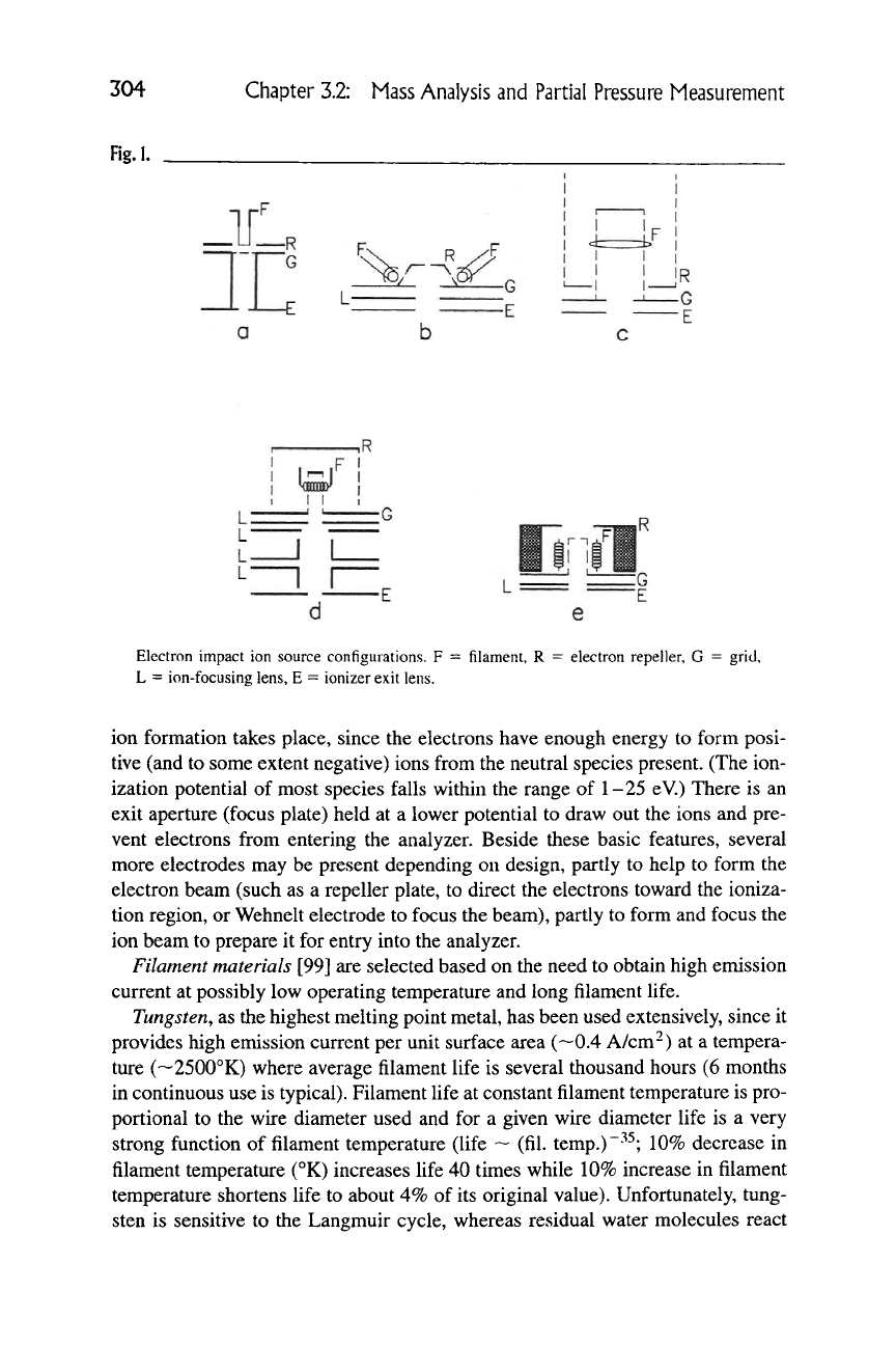
Electron impact is the most widely used method because of its simplicity,
ruggeddness, and high sensitivity. In this source a filament is heated to a temper-
ature high enough for thermionic emission (Figure 1). A grid, held at a potential
higher than the filament, accelerates the electrons (50-150 eV range). The accel-
erated electrons then enter the "ionization chamber," or ion cage, a region where
304
Chapter 3.2: Mass Analysis and Partial Pressure Measurement
Fig.l.
_1L.
3"C
^/ -^ n 1 I 1
I I.
1
L
L
—
L —
^R
1 1 1
H H
111 ill
Electron impact ion source configurations. F = filament, R
L = ion-focusing lens, E = ionizer exit lens.
electron repeller, G = grid.
ion formation takes place, since the electrons have enough energy to form posi-
tive (and to some extent negative) ions from the neutral species present. (The ion-
ization potential of most species falls within the range of 1-25 eV.) There is an
exit aperture (focus plate) held at a lower potential to draw out the ions and pre-
vent electrons from entering the analyzer. Beside these basic features, several
more electrodes may be present depending on design, partly to help to form the
electron beam (such as a repeller plate, to direct the electrons toward the ioniza-
tion region, or Wehnelt electrode to focus the beam), partly to form and focus the
ion beam to prepare it for entry into the analyzer.
Filament materials [99] are selected based on the need to obtain high emission
current at possibly low operating temperature and long filament life.
Tungsten, as the highest melting point metal, has been used extensively, since it
provides high emission current per unit surface area (—0.4 A/cm^) at a tempera-
ture (~2500°K) where average filament life is several thousand hours (6 months
in continuous use is typical). Filament life at constant filament temperature is pro-
portional to the wire diameter used and for a given wire diameter life is a very
strong function of filament temperature (life ~ (fil. temp.)"^^; 10% decrease in
filament temperature (°K) increases life 40 times while 10% increase in filament
temperature shortens life to about 4% of its original value). Unfortunately, tung-
sten is sensitive to the Langmuir cycle, whereas residual water molecules react
3.2.3 Ion Generation and Ion Sources 305
with the hot filament, forming volatile tungsten oxides and hydrogen. The oxides
deposited on cooler surrounding surfaces will eventually be reduced by the hy-
drogen, resulting in a water molecule available for the next cycle and leaving a
metallic deposit behind. This may create unwanted current path on isolators or al-
ter potentials in the source. Another unwanted reaction of tungsten filament is
its reaction with oxygen, partly because of the deposit of tungsten oxide — which
may form insulating layers on metal electrodes. The charge-up of these layers can
result in change in the potentials in the source leading to inefficient source opera-
tion, unsatisfactory peak shapes, etc. Also, the carbon impurities in the tungsten
wire reacts with the oxygen on the surface, while the carbon is continuously
dif-
fusing to the surface. The resulting CO and
CO2
produce an annoyingly high back-
ground level. Molecular hydrogen dissociates at the filament, forming atomic hy-
drogen that is readily adsorbed by most surfaces. As a result, hydrogen signal is
less
—
a
local "pumping" of hydrogen occurs.
Rhenium is more resistant to water cycle, but its evaporation rate is about 150
times higher than that of tungsten for the same emission current density, there-
fore operation at a lower temperature is recommended. It does not form stable
carbides, therefore the high CO background experienced with W filament can be
lessened. Its resistance to other compounds is also known to be higher, although
halogen compounds will form oxyhalides
[100].
(Tantalum—another high-melting-point material —
is
useless as a filament
material because of its tendency to absorb large amounts of hydrogen, which at
high temperatures will alter its crystal structure causing extreme brittleness and
short life.)
Thoriated tungsten is a
0.5-1%
Th02 doped tungsten wire. At operating tem-
peratures the thoria will diffuse to the previously carburized surface, providing
free thorium. This monolayer will reduce the work function of tungsten by almost
a factor of
two,
providing high emission current per unit surface area (~4A/cm^)
at lower temperatures, therefore extending life.
Thoria-coated cathodes are made by a different process, wherein the base metal
is coated with a thick layer of Th02, which is activated by operation in vacuum.
The lower work function again enables operation at lower temperatures
[101],
therefore the base metal does not have to be a refractory metal. The choice is
therefore often iridium or rhodium to obtain a much higher level of oxidation re-
sistance. (Accidental exposure to air will not result in sudden burnout.) Even after
repeated exposure to corrosive gases constant emission characteristics were ob-
served. This filament provides advantages when operating at high ionizer pres-
sure because sample-filament reactions are suppressed, but also at extremely low
pressures where the lower filament temperature keeps outgassing of surfaces at a
lower level.
Lanthane
hexaboride-codittd
base metals can (and have to) be operated at lower
temperatures (<1400°K) also, to ensure long life and resistance to active gases.
At higher temperatures, the boron tends to diffuse into the base metal, deteriorat-
306 Chapter 3.2: Mass Analysis and Partial Pressure Measurement
ing its properties and the LaB^ evaporation rate will become high. Rhenium is the
most resistant to this boron diffusion, and so a preferred choice as base metal for
lanthane hexaboride cathodes. As opposed to pure metals, coated cathodes can be
poisoned by aggressive gases, resulting in elevated work functions.
Ion source configurations are as diverse as the special requirements they have
to meet. Still, it is possible to categorize at least the typical arrangements used in
commercial quadrupole instruments.
Axial (radial) sources are usually offered as the standard source. The name ax-
ial refers to either that the sample enters in the axis of the instrument (quadrupole
rods) or that the electron beam is in-axis (and the sample enters through all the
openings in the source). The name radial refers to the radial symmetry of the
arrangement, when ring-type filaments are used. Electrons are generated by a
filament either on axis, or by filament(s) in a plane perpendicular to the axis (ring-
type filament, or several filaments forming a polygon). These are intended for
general gas analysis or work at medium pressure (10~^-10~^ torr, ~10""^-10~^
Pa).
A version called
closed,
gas-tight, or enclosed design is available to improve
trace sensitivity. In this version the ionization chamber is separated from the
filament and the rest of the analyzer by small apertures, enabling it to operate it
at a higher pressure. This will increase sample-background ratio also limiting
sample-filament interactions. The sample is led directly into this chamber through
a small pipe.
Cross-beam sources will lead the sample into the source in a line perpendicular
to the axis of the analyzer. This is especially suited for molecular beams or poorly
coUimated beams of condensable material or aggressive gases. Liquid-nitrogen-
cooled beam stops or built-in beam shields then permit the continuous operation
on vacuum deposition systems, molecular beam epitaxy, etc., without forming
disturbing deposits in the analytical instrument. Again, an "open" and a "closed"
version or versions integrated with ion extraction optics may be available.
Grid,
open, RGA, or UHV source are all names covering an extremely open
design for high pumping speed, low outgassing rate, and low electron-stimulated
desorption. These sources are used at extremely low pressures, residual gas analy-
sis,
and UHV work. Instead of metal sheets, mesh are used for electron repulsion,
cage,
etc. If the instrument is intended as a residual gas analyzer, this may be the
standard ion source.
Figure
1
shows some typical configurations found in partial pressure analyzers.
(Sources a, d, e are variations of an axial-type source, c is a grid source, and b can
be used as a cross-beam source.) The electrons emitted by the filament (F) are ac-
celerated by the positive voltage applied to the grid (G) and directed toward the
ionization chamber in the center by the negative voltage applied to the repeller
(R) (both compared to the filament potential). Ions are extracted from the ioniza-
tion region by the negative voltage applied to the lens (L) or the exit aperture (E)
(voltage compared to the grid potential).
3.2.3 Ion Generation and Ion Sources 307
Special construction ion sources have been developed for particular applica-
tions,
particular analyzers or trying to deal with the imperfections of standard
sources. The most common ion source used in magnetic
j-^c^c^r
instruments is some
variant of the traditional construction described by Nier
[102].
An improved ver-
sion of the source provides additional focusing to improve transmission through
the analyzer and can be operated at higher accelerating voltages without arcing
[103].
Further improvements replaced the rectangular lens elements with ones
with circular symmetry, constructing the ion beam along the originally long side
of the rectangular element. This resulted in better precision, better transmission
and sharper focusing
[104].
A hemispherical cavity in the focusing (ion exit) elec-
trode acting as a Pierce lens can keep the potentials penetrating into the ion for-
mation chamber nearly constant. Thereby the ions are formed along an equipo-
tential surface, keeping their energy spread low
[105].
A source providing wide
electron energy range (19-70 eV), the incorporation of
a
spare filament and about
a 10-fold differential pumping factor have been described for space application
[106].
Several computer trajectory calculations were performed, aiming at pro-
ducing an ion beam of higher current density, with mixed success [107,108,109],
or aiming at understanding space charge and mass discrimination effects.
For ion sources operated with quadrupole instruments, trajectory tracing has
also been used to improve ion yield and sensitivity. In an effort to eliminate ions
from electron stimulated desorption
[110],
the electron-accelerating voltage is
modulated and the ion current is measured in a phase-lock loop
[111].
To increase
the high operating limit of the ion source, auxiliary electrodes were installed at
the inlet into the ionization chamber providing short, parallel electron path
[112].
Linear source response has been reported with such a source up to 10~^ torr
(~10-^Pa)[113].
Photo ionization is a "soft" ionization relative to electron impact. Since chem-
ical bonds are generally not broken, the amount of fragmentation or the strong
signal from the matrix can be suppressed. On the other hand, the sensitivities of
these sources are only a portion of the sensitivity of an electron impact source.
Compared to low-energy electron ionization (<15 eV), it is much easier to pro-
duce photons in a narrow energy range than electrons. Also, just above the ion-
ization potential, the efficacy of electron impact ionization is low compared to
the impact with photons. Trace contaminants in air have been measured using the
selective laser ionization — choosing the photon source so that the energy of the
light is above the threshold ionization potential for contaminants but below that
of the main components
[114].
Laser ionization opens up the way of extending
partial pressure measurement in the extreme-high-vacuum range (less than 10"^
torr,
—10""^
Pa) by avoiding filament- and electron-induced desorption related
problems
[115].
Alpha ionization source is a way to avoid hot-cathode-sample reactions. The
alpha radiation from a ^^^Po source provides a "cold" way to produce ions. It
308 Chapter 3.2: Mass Analysis and Partial Pressure Measurement
is extremely stable, being independent from external power supplies. However,
to prevent sublimation of polonium and the resulting increase in noise level of
the multiplier, it is necessary to place the source in a separate HV chamber with
a 2-4 fi Ni window. The sensitivity of the source was only about 10"^ A/torr
(-10-^^ A/Pa)
[116].
Field ionization is another method to avoid thermal effects. However, in its
general form it produces relatively energetic ions (keV range) and if coupled to a
quadrupole analyzer, deceleration is required, to slow down the ions into the
5-50 eV range. Complicated ion optics are necessary to prevent beam losses. A
single pointlike source, where the sample is flowing axially through a volcano-
shaped hole (—20 yLt) of the field emitter, with a grid counterelectrode held at
1-3 keV potential is capable to achieve sensitivity around 10"^ A/torr (~
10"
^^
A/
Pa)
[117].
Field emitter arrays, having a huge number of emitters on a small area
can achieve emission currents around 1 mA. Using this semiconductor-type de-
vice in place of a filament, low-energy ions can be generated since the high volt-
age (~100 V) is between the base and the gate of the semiconductor device and
does not affect the potential of the ionization chamber. Sensitivity approaching
that of a standard hot-cathode electron impact ionizer can be achieved (10~^ A/
torr;
—lO""*
A/Pa), but fluorine outgassing from the semiconductor is a problem
yet to be solved
[118].
Chemical ionization is a soft ionization method that found its way to partial
pressure analysis by the name of gas secondary ion mass spectrometry. In this
method a reagent gas (such as Kr, Xe, or CH4) is ionized in a chamber by electron
impact ionization. The resulting ions are extracted by electric fields and driven to
the charge exchange chamber where, through ion molecule collisions with the
sample, charge transfer takes place. Those constituents of the sample that have
ionization energies below the noble gas ions are ionized without significant frag-
mentation (no electron bombardment). This method, beside being "soft," also
opens the way to distinguish between different ion species of the same MIQ based
on differences in their ionization energies (CO vs. N2 or CH3OH vs. O2).
3.2.4
ION SEPARATION AND ANALYZERS
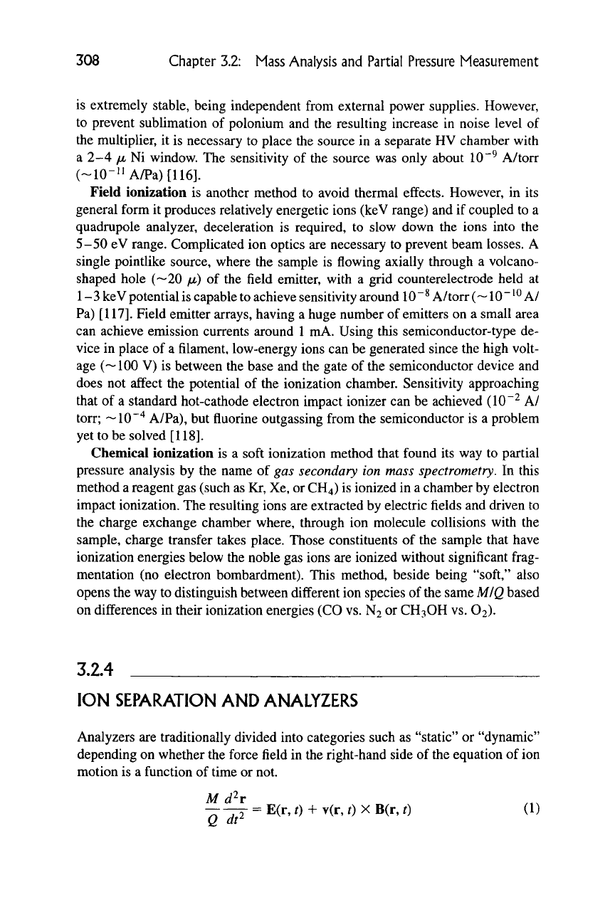
Analyzers are traditionally divided into categories such as "static" or "dynamic"
depending on whether the force field in the right-hand side of the equation of ion
motion is a function of time or not.
M d'^r
— -ry = E(r, t) + v(r, t) X B(r, t) (1)
Q dt"-
3.2.4 Ion Separation
and
Analyzers
309
(M = mass of the ion, Q = electric charge of the ion, E(r, t) = electric field in-
tensity, v(r, t) = velocity of the ion, B(r, t) = magnetic induction, r = position
vector of
ion,
t = time)
Since the force field used for separation is created by magnetic and/or electric
fields, another conventional way of categorization is referring to "magnetic" or
"electric" instruments. Whereas magnetic instruments usually apply a combina-
tion of magnetic and electric field, instruments that apply electric field only are
mostly of the "dynamic" type such as the electric quadrupole. Dynamic instru-
ments can be further divided into "path stability" or "time stability" instruments
depending on whether the ions of the selected mass-to-charge ratio are separated
from the others based on their path (electric quadrupole, magnetic sector), or
based on the time during which they travel a certain distance (time-of-flight).
3.2.4.1 Electric Quadrupole Analyzers
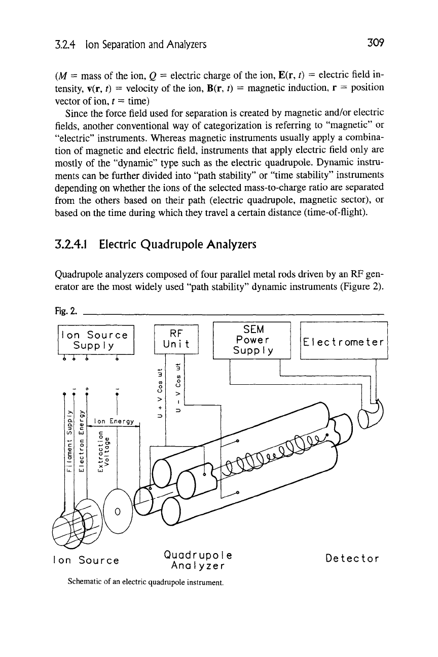
Quadrupole analyzers composed of four parallel metal rods driven by an RP gen-
erator are the most widely used "path stability" dynamic instruments (Figure 2).
Fig.
2.
1
on
S
^ i,
Source
upply
^
<^
RF
Uni
t
SEM
Power
SuppIy
EIect rometer
I
«r,
c,^,.^^^
Quadrupole
Ion Source Anolyzer
Schematic of
an
electric quadrupole instrument.
Detector
