Hillert M. Phase Equilibria, Phase Diagrams and Phase Transformations: Their Thermodynamic Basis
Подождите немного. Документ загружается.


9.4 Sections of molar phase diagrams 195
Solution
This is a three-dimensional diagram, r = 3, and the dimensionality of the α − β line
is one, b = 1. We get D
−
= r − b = 3 − 1 = 2. The number of phases has decreased
from 4 to 2. We have moved into the α + β two-phase region by crossing the α − β line.
The dimensionality of the β point is zero, b = 0, and we get D
−
= r − b = 3 − 0 = 3.
The number of phases has decreased from 4 to 1. We have moved into the β one-phase
region by crossing the β point.
9.4 Sections of molar phase diagrams
A diagram with a full set of molar axes may be called a complete molar phase diagram.
For practical reasons one often likes to reduce the number of axes. A popular method is
to section at a constant value of a potential, e.g. P or T. The resulting diagram looks just
like a complete molar phase diagram for a system with one component less. Another
method is to section at a constant value of a molar variable, a so-called isoplethal section
or an isopleth.
Since all phase fields in a molar phase diagram have the same dimensionality as
the phase diagram has axes, all kinds of phase fields may show up in that kind of
section whereas a phase field with the maximum number of phases (i.e. for an invariant
equilibrium) will disappear in an equipotential section because the section cannot be
expected to go exactly through a given point. The topology of a molar section is simplified
if it is again accepted that it will not be possible to place a section exactly through a point.
All two-dimensional sections with molar axes will be composed of the elementary unit
shown in Fig. 9.8 and all three-dimensional sections will be composed of the elementary
unit shown in Fig. 9.9, independent of how many potential or molar axes have been
sectioned. Of course, if one adds a component, one must section once more in order
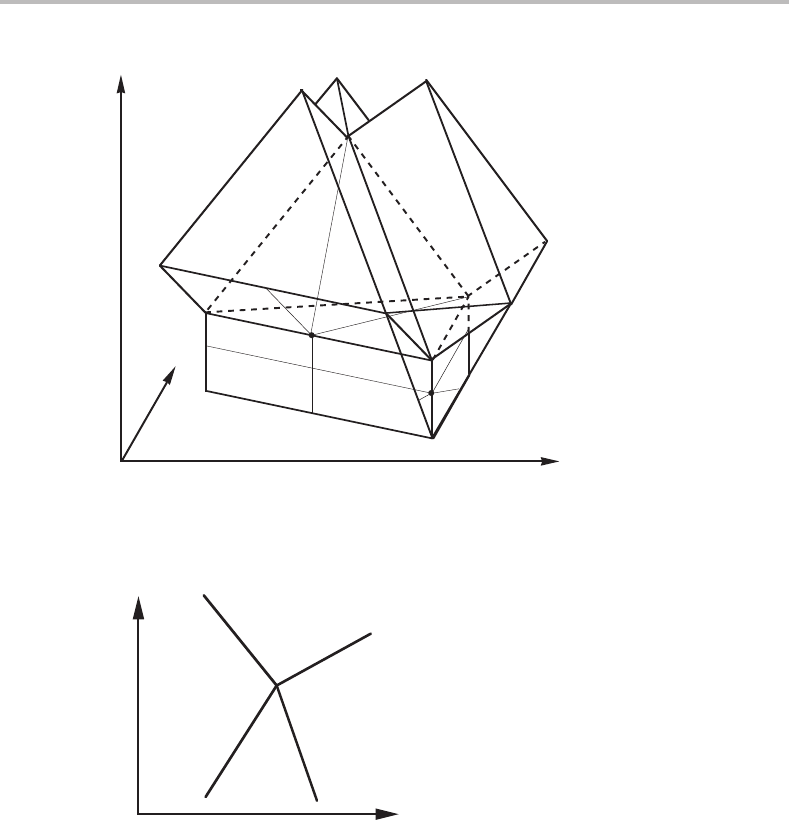
to keep the number of dimensions. As an example, two sections through Fig. 9.4 are
indicated in Fig. 9.10.Ineach case, the section gives the same arrangement of lines as in
Fig. 9.8(a). Furthermore, the MPL boundary rule applies to the sections, since the value
of r – b does not change by sectioning.
Inspection of the two sections in Fig. 9.10 reveals that one shows an intersection
between phase fields of 2, 3, 3 and 4 phases and the other 1, 2, 2 and 3 phases. We may
thus give the general picture shown in Fig. 9.11.For the sections shown in Fig. 9.10 we
have e = 3 and 4, respectively, where e is the highest number of phases in any of the two
adjoining phase fields. In fact, the maximum value of e in a two-dimensional diagram,
which is also the maximum number of phases in a phase field, depends upon the number
of sectioned molar axes, n
ms
,
e
max
= 3 + n
ms
. (9.12)
Exercise 9.5
On the right-hand side of the tetrahedron in Fig. 9.10 there is a triangular prism. Make
a section through that prism parallel to the side of the tetrahedron. Make a sketch of the
196 Molar phase diagrams
z
B
S
m1
V
m1
Figure 9.10 Two sections through the molar phase diagram of Fig. 9.4. The sections are shown
with thin lines.
e–2
or
e
e–1 e–1
e
or
e–2
X
j
m1
X
k
m
Figure 9.11 Elementary unit of a molar phase diagram, sectioned a sufficient number of times to
make it two-dimensional. The diagram may have units with different e values from 3 up to a
maximum, determined by the number of sectionings.
intersection obtained at the front edge of the prism. Indicate the number of phases in the
four adjoining phase fields.
Hint
It may be useful to go back to the Exercise 9.4.
Solution
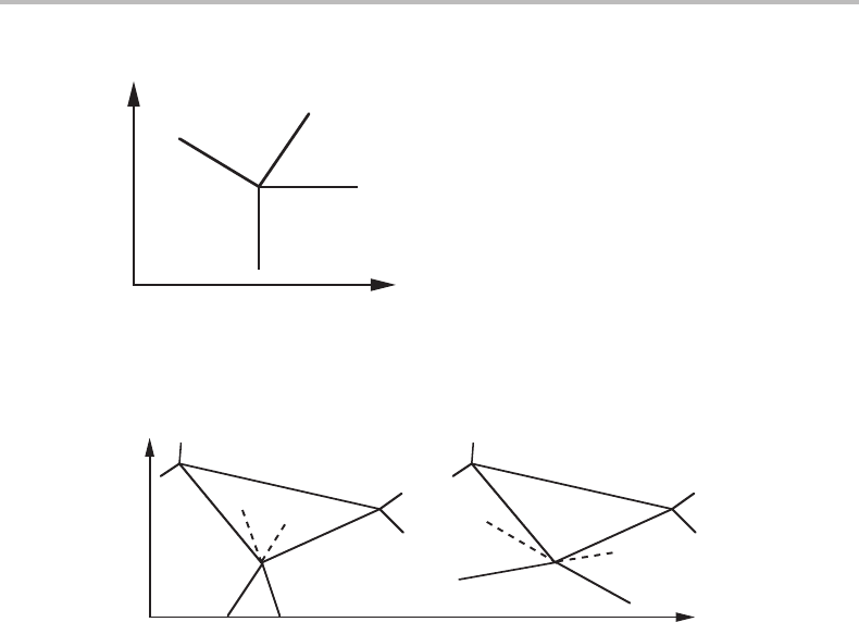
The solution is given in Fig. 9.12.
9.5 Schreinemakers’ rule 197
1
2
3
2
z
B
S
m1
Figure 9.12 Solution to Exercise 9.5.
α+β
α+β+γ
β+γ
α+γ
α
β
γ
α
β
γ
α+β
α+γ
β+γ
α+β+γ
X
j
m1
(a) (b)
X
k
m
Figure 9.13 Elementary unit of a phase diagram with two molar axes. Two of the phase
boundaries of the one-phase field are shown.
9.5 Schreinemakers’ rule
When studying isobarothermal sections of ternary diagrams Schreinemakers [13] found
that the extrapolations of the boundaries of the one-phase field in the elementary unit
must either both fall inside the three-phase fields or one inside each of the two two-
phase fields. This is illustrated in Fig. 9.13 and is called Schreinemakers’ rule. It can be
generalized in the following way [14].
Let us examine if Schreinemakers’ rule applies to different e values and start by
considering a complete phase diagram constructed with molar axes only. A discussion of
thermodynamic properties should then be based upon the internal energy. For reversible
changes we obtain
dU = T dS − PdV +
c
1
µ
i
dN
i
. (9.13)
In Section 4.6 we saw that it is always possible to introduce a new set of components
instead of the old one by combining the components in a new way as long as we get
a complete set of independent components and do not change the value of the sum,
µ
i
dN
i
.Wecan do so by selecting c points in the compositional space and make sure
that they can be used to define a new set of independent components by checking that
three of them never fall on a line, four of them never fall on a plane, etc. We shall use this
method of changing to a new set of components but we shall then consider entropy and
198 Molar phase diagrams
α
α
kk
j
j
α+k + j
α+k + j
(a) (b)
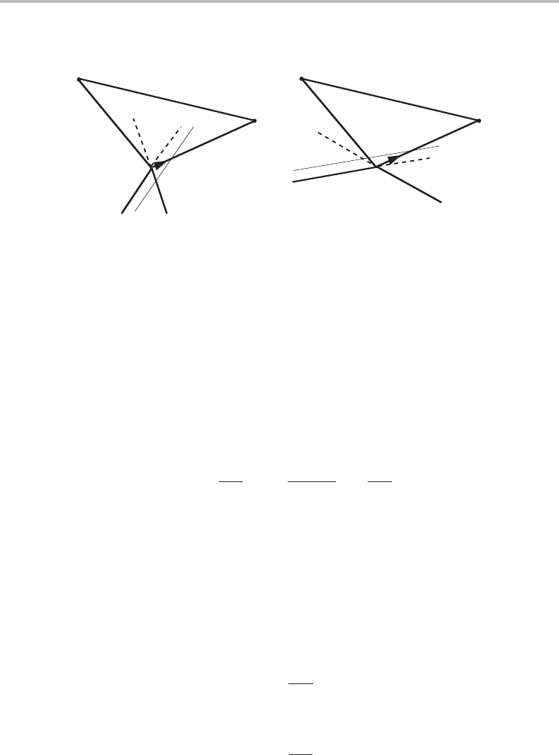
Figure 9.14 General proof of Schreinemakers’ rule.
volume as components, whose amounts are expressed by S and V, and whose chemical
potentials are T and −P, respectively. The introduction of c + 2new components instead
of the old ones will now be effected by selecting c + 2 points in the state diagram. They
will each be identified by an index d.
We can follow the procedure outlined in Section 4.6 and obtain
dU =
c+2
1
µ
i
dN
i
=
c+2
1
µ
d
dN
d
, (9.14)
where µ
d
=
i
a
d
i
µ
i
and N
i
=
d
a
d
i
N
d
.For these generalized chemical potentials,
the following Maxwell relation is obtained
∂µ
j
∂ N
k
N
j
=
∂
2
U
∂ N
k
∂ N
j
=
∂µ
k
∂ N
j
N
k
. (9.15)
When considering the cases in Fig. 9.13 with a tie-triangle in the section, we shall include
the β and γ corners in the set of new components. In a more general case we shall denote
them by k and j (see Fig. 9.14).
At the point under consideration, one of the two boundaries, the extrapolations of
which we discuss, represents equilibrium with k, and is thus an equipotential line for k
in α.Ifitextrapolates outside the α − k − j triangle, the potential of k must increase on
moving closer to the point j, because this path intersects equipotential lines for k in α
situated closer to the point k, i.e.
∂µ
k
∂ N
j
> 0 (9.16)
(see thin line in Fig. 9.14(b)). Then, from the Maxwell relation,
∂µ
j
∂ N
k
> 0 (9.17)
It follows that the second boundary must also extrapolate outside the α − k − j triangle.
On the other hand, if the k boundary extrapolates into the triangle, a movement towards
the point j will intersect equipotential lines for k further away from the point k (see thin
line in Fig. 9.14(a)). Both derivatives must then be negative, and both boundaries must
9.5 Schreinemakers’ rule 199
1500
1400
1
1300
T (K)
1200
1100
3
1000
0 0.5 1.0
mass-% C
1.5 2.0
6
5
5
4
3
2
3
4
2
3
4
5
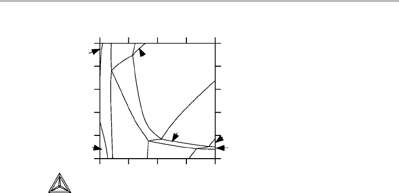
Figure 9.15 Calculated phase diagram for system with seven components. The complete phase
diagram has two potential axes and six molar axes and has been sectioned at one constant
potential, P, and five constant molar quantities, x
i
. Schreinemakers’ rule holds at all
intersections. Numbers given are number of phases in each phase field.
extrapolate into the triangle. It has thus been shown that the extrapolations of both phase
boundaries under consideration must fall either outside the highest-order phase field or
inside it, in agreement with Schreinemakers’ rule. It may be emphasized that the rule also
holds for equipotential sections. In order to prove it in such a case, one must use a Maxwell
relation based on a thermodynamic function which allows the corresponding potentials
to be kept constant, for instance G in the case actually considered by Schreinemakers,
constant T and P.
In the derivation of Schreinemakers’ rule it is essential that the two boundaries of
the highest-order phase field of those considered are straight lines. That this happens
in the ternary case under isobarothermal conditions is self-evident because then the tie-
triangle is situated in the plane of the diagram. In a quaternary system the sides of a
four-phase equilibrium will be planar and the intersections shown in a two-dimensional
section will be straight lines. The components k and j then represent two-phase mixtures
situated in the section. On the other hand, a three-phase equilibrium will not be bounded
by planar sides and its boundaries in the two-dimensional section will not be straight
lines. Then the boundaries of the one-phase field will not be equipotential lines for any
components k and j chosen in the section. It may be concluded that the proof, given above,
is not rigorous except when an equilibrium of the highest order allowed in the section
is involved. However, experience shows that Schreinemakers’ rule is obeyed in most
cases, and it may be used as a convenient guide when other information is lacking. As
an example, the result of a computer-operated calculation of a section through a seven-
component system is presented in Fig. 9.15. The rule is satisfied at all the intersections
in this diagram.
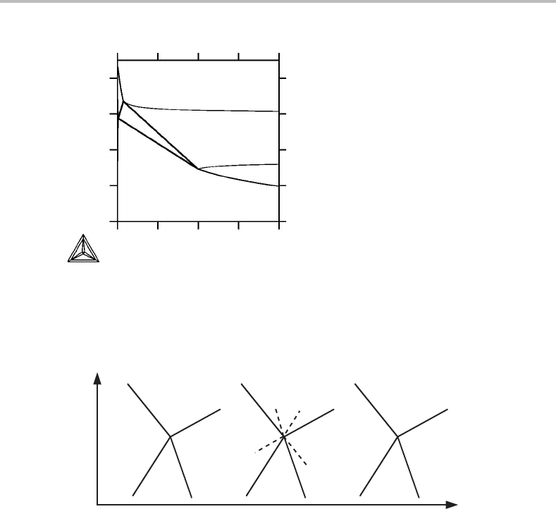
Figure 9.16 shows an apparent violation of Schreinemakers’ rule at the corner of the
bct phase field. However, this is not a true phase diagram because S
m
and z
i
never appear
in the same set of conjugate variables in Table 9.2.
200 Molar phase diagrams
90
80
70
60
50
020
S
m
(J/molK)
fcc+bct
lip+bct
lip
bct
40
z
Sn
60 80
Figure 9.16 S
m
, z
Sn
diagram for Pb–Sn at 1 bar. It shows an apparent violation of
Schreinemakers’ rule but is not a true phase diagram.
e –1
e –2
or
e
e
or
e –2
e –1
X
j
m1
X
k
m
(a) (b) (c)
Figure 9.17 Use of Schreinemakers’ rule to decide which phase fields have equal number of
phases.
Usually, Schreinemakers’ rule is used to predict the directions of phase boundaries.
On the other hand, if the phase boundaries are given, for instance from calculation or
experiment, then the rule can help to give the number of phases in the various phase
fields. Suppose the arrangement in Fig. 9.17(a) is given, but the numbers of phases in
the four adjoining phase fields are not known. One should then extrapolate all the lines,
as shown in Fig. 9.17(b).Two of the phase fields will contain one extrapolation each,
and these phase fields will be opposite to one another. According to Schreinemakers’
rule, these will be the phase fields with the same number of phases, e −1inFig.9.17(c).
Of the two remaining phase fields, one will contain two extrapolations and the other
none. These phase fields will contain one phase more and one phase less than the others,
respectively. However, the rule does not allow us to tell which has more and which less.
It would be possible to predict the number of phases in all the phase fields of Fig. 9.15
by this method, if it were known that the phase field in the upper left corner has one
phase.
9.6 Topology of sectioned molar diagrams 201
1
Figure 9.18 See Exercise 9.6.
1
2
2
2
2
2
3
3
3
3
4
1
2
Figure 9.19 Solution to Exercise 9.6.
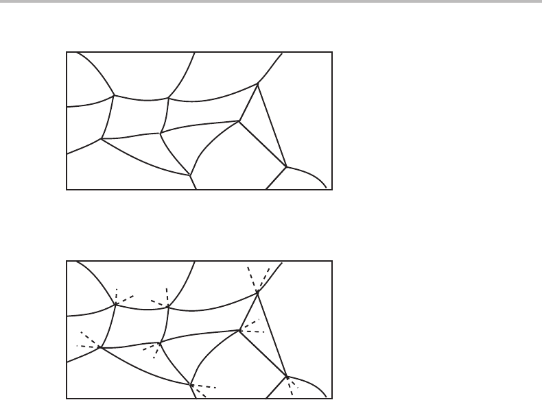
Exercise 9.6
A diagram for a multicomponent system is given in Fig. 9.18 but the numbers of phases
have been left out except for one phase field. Try to decide the numbers of phases in all
the other phase fields.
Hint
Discuss first what kind of phase diagram it is.
Solution
It looks like a molar diagram because at each point of intersection there are four lines.
It may thus be reasonable to use Schreinemakers’ rule. The result is shown in Fig. 9.19.
9.6 Topology of sectioned molar diagrams
Before leaving the discussion of sections of molar phase diagrams we should further
consider the topology of diagrams with several phases. Figure 9.8 showed the elementary
unit of a two-dimensional molar diagram. The result of sectioning can vary depending
upon the direction of sectioning and the regularity of the diagram before sectioning.
However, topologically the whole section can be regarded as composed of intersecting
202 Molar phase diagrams
1
1
2
2
2
2
3
3
3
3
3
3
4
4
4
4
4
4
5
5
5
5
5
5
6
6
3
3
(a) (b)
Figure 9.20 Two diagrams topologically equivalent to the sectioned molar phase diagram of
Fig. 9.15.
1
(a) (b) (c)
1
1
111111
1
11
2
2
2
2
2
2
2
222
2
2
22
22
3
33
223
3
33
3
3
3
3
3
3
4
4
4
4
4
4
4
5
5
33
334 4
3
33
3
2
22
2
22
3
4
4
4
5
1
Figure 9.21 Some possibilities for the topology of a sectioned molar phase diagram with several
phases. Both axes are molar axes.
Fe W
β
µ
σ
α
Cr(a)
α
α
α
β
β
β
σ
µ
µ
µ
α
(b)
Figure 9.22 (a) The Fe–W–Cr phase diagram at 1 bar and 1673 K. α and β are both bcc but do
not mix completely. µ and σ are intermetallic phases. (b) Topologically equivalent diagram but
drawn with lines without any sharp points. These lines represent the limit of existence for one
phase each, as given by the letters outside the triangle. The circle is the limit for σ.
9.6 Topology of sectioned molar diagrams 203
γ+δ+ε
γ+δ+ε
γ+δ+ε
α+γ+δ+ε
α+δ+ε
α+δ+ε
γ+δ+ε
δ+ε
β+δ+ε
β+ε
α+β+ε
α+δ+ε α+ε
α+ε α+β+ε
α+γ+ε
ε
β+ε
γ+δ+ε
δ+ε
γ+δ+ε
Figure 9.23 See Exercise 9.7.
lines, and the elementary unit will be the same as in Fig. 9.8(b).Bythe same reasoning,
a three-dimensional diagram will have elementary units like the one in Fig. 9.9 and will
give units like the one in Fig. 9.8(b) after sectioning. A many-dimensional molar phase
diagram, after being sectioned a sufficient number of times, may look something like the
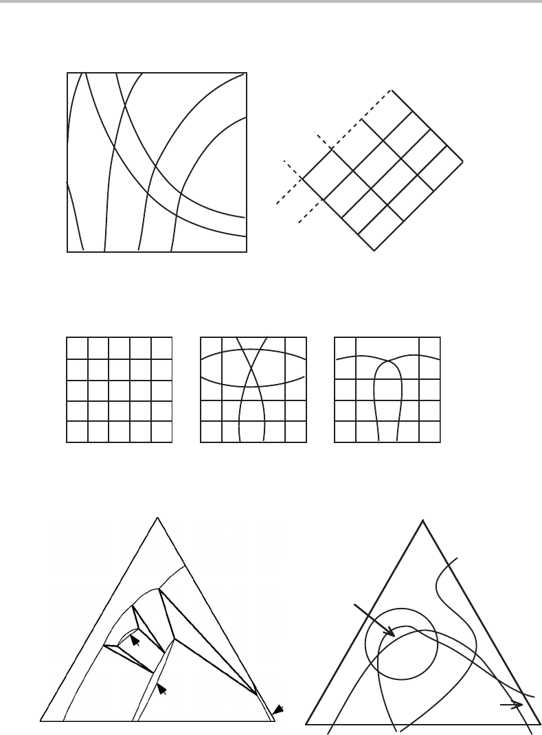
one illustrated in Fig. 9.20(a).Itwas constructed to be topologically equivalent to the
phase diagram in Fig. 9.15.InFig. 9.20(b) it has been further simplified but it still has
the same topology. This is an unusually simple case. The lines may very well intersect
in a more complicated manner, as illustrated in Fig. 9.21.
The observation by Masing can be generalized. For each one of the lines in a two-
dimensional section of a molar phase diagram there is a phase which ceases to exist
on the line. It is illustrated for a complicated case in Fig. 9.22(a), using the topo-
logically equivalent diagram in Fig. 9.22(b). These lines running through a compli-
cated phase diagram have been called ‘zero-phase-fraction’ lines by Gupta, Morral
and Nowotny [15] and they can be used as a valuable tool for identifying the phase
fields and even for constructing a phase diagram from experimental information. The
same principle applies to the surfaces in three-dimensional sections of molar phase
diagrams.
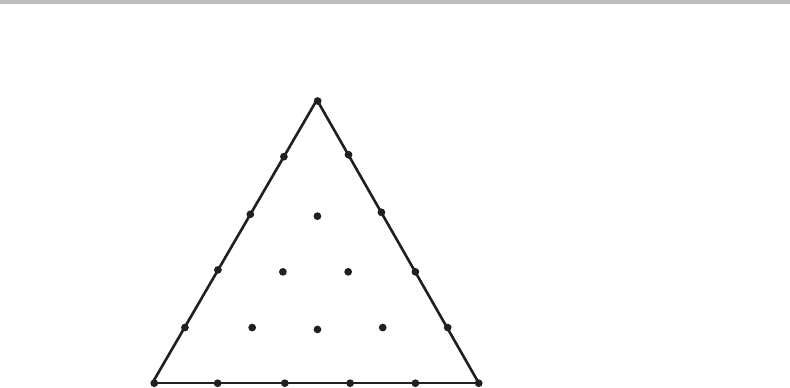
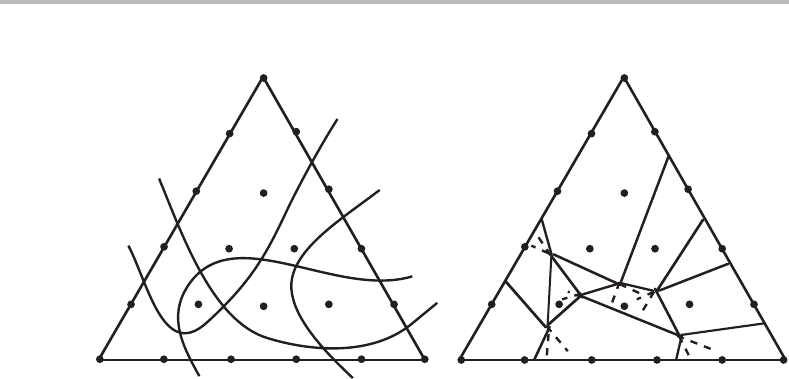
Exercise 9.7
In order to investigate the phase relations in a quinary system Gupta, Morral and Nowotny
established equilibrium in 21 alloys by isothermal treatment at 1400 K and 1 bar. All
alloys had the same molar content of two components. The phases found in the various
alloys could thus be shown in a composition triangle (see Fig. 9.23,where the composi-
tions are represented by the relative fractions of the three remaining components). Draw
a reasonable phase diagram.
204 Molar phase diagrams
γ
γ
δ
δ
α
α
(a) (b)
β
β
2
2
2
2
3
3
3
3
3
4
1
Figure 9.24 Solution to Exercise 9.7.
Hint
The diagram is a molar phase diagram. Start by drawing lines showing the limit of
existence of each phase (zero-phase-fraction lines). Improve the diagram by making the
various phase boundaries reasonably straight. Phase boundaries for invariant equilibria
must be quite straight. Improve the diagram further by applying Schreinemakers’ rule.
Solution
At constant T and P the maximum number of phases in a quinary system is five. None
of the alloys falls in such a phase field. All the phase boundaries may thus be curved but
we may find that it is possible to use straight lines which is preferable when we do not
know in which direction a line should be curved. Figure 9.24 shows a possible solution.
