Hillert M. Phase Equilibria, Phase Diagrams and Phase Transformations: Their Thermodynamic Basis
Подождите немного. Документ загружается.


9
Molar phase diagrams
9.1 Molar axes
If one starts from a potential phase diagram, one may decide to replace one of the poten-
tials by its conjugate variable. However, the potential phase diagram has no information
on the size of the system and one should thus accept introducing a molar quantity rather
than its extensive variable. By replacing all the potentials with their conjugate molar
variables, one gets a molar diagram. One would like to retain the diagram’s character
of a true phase diagram, which means that there should be a unique answer as to which
phase or phases are stable at each location. In this chapter we shall examine the properties
of molar diagrams and we shall find under what conditions they are true phase diagrams.
Only then may they be called molar phase diagrams.However, we shall start with a
simple demonstration of how a diagram changes when molar axes are introduced.
Figure 9.1(a)–(d) demonstrates what happens to a part of the T , P potential phase
diagram for Fe when S
m
and V
m
axes are introduced. Initially the P axis is plotted in the
negative direction because V is conjugate to −P. It can be seen that the one-phase fields
separate and leave room for a two-phase field. It can be filled with tie-lines connecting the
points representing the individual phases in the two-phase equilibrium. It is self-evident
how to draw them when one axis is still a potential but they yield additional information
when all axes are molar (Fig. 9.1(d)).
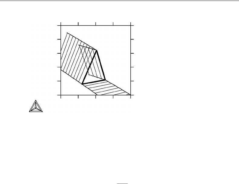
Figure 9.2(a)–(d) is a similar demonstration using a part of the Fe phase diagram with
a three-phase equilibrium, a triple point. It forms a tie-triangle when both potentials
have been replaced (Fig. 9.2(d)). All the phase fields are then two-dimensional. One may
also notice that each one-phase field from the potential diagram maintains its general
shape. Their corners still have angles less than 180
◦
(see the 180
◦
rule formulated in
Section 8.3).
It should be emphasized that the phase fields never overlap in these diagrams. They
may all be classified as true phase diagrams because each point represents one and only
one phase equilibrium. Three requirements must be fulfilled in order for this to happen.
Firstly, the two one-phase fields meeting at a two-phase line in a potential phase diagram
must move away from each other and leave room for an extended two-phase field, when
a molar axis is introduced. Secondly, the one-phase field extending from the two-phase
field in the direction of increasing values of a potential must also extend to increasing
values of the conjugate molar variable that is introduced. If it goes the other way, it
would overlap the two-phase region. The other one-phase field must extend in the other

186 Molar phase diagrams
10
(a) (b)
(c) (d)
70
73
68
800 1100 58 74
S
m
(J/mol K)
bcc
P (kbar)
T (K)
fcc
bcc
V
m
⋅ 10
7
(m
3
)
fcc
bcc
fcc
bcc
fcc
Figure 9.1 Introduction of molar axes instead of potential axes in a part of the unary phase
diagram for Fe with two phases.
80
(a) (b)
(c) (d)
140
70
64
500 1000 45 65
S
m
(J/mol K)
bcc
P (kbar)
T (K)
fcchcp hcp
bcc
V
m
⋅ 10
7
(m
3
)
fcc
hcp
bcc
fcc
hcp
bcc
fcc
Figure 9.2 Introduction of molar axes instead of potential axes in a part of the unary phase
diagram for Fe with three phases. All phase fields here become two-dimensional.

9.1 Molar axes 187
60
58
56
54
52
50
−28 −26 −24
Helmholtz energy (kJ/mol)
Entropy (J/molK)
−22 −20
hcp
fcc
bcc
Figure 9.3 S, H diagram for Fe. This is not a true phase diagram because S and H never appear in
the same set of conjugate variables.
direction, before as well as after replacing the potential with the conjugate molar variable.
Thirdly, a one-phase field is nowhere allowed to fold over itself.
The last two requirements are fulfilled if the system is everywhere stable because of
the stability condition from Eq. (6.28),
∂Y
b
∂ X
b
Y
c
,X
d
> 0. (9.1)
The potential Y
b
and its conjugate variable X
b
thus increase in the same direction.
However, as already emphasized, this stability condition requires that all the variables to
be kept constant, here represented by Y
c
,X
d
, come from the same set of conjugate pairs
as Y
b
and X
b
. Nine such sets were presented in Table 3.1 but it is necessary to examine
what happens to them when the size of the system is measured in different ways. This
will be discussed in the next section. Figure 9.3 is an example of what can happen if
one uses two molar variables which do not appear in the same set of conjugate variables,
S and H. It is not a true phase diagram according to the definition given at the very
beginning of this section. Other cases will be discussed in Section 10.7.
The first requirement can be tested as follows, using the form of the Gibbs–Duhem
relation with molar quantities introduced in Eq. (8.4),
dµ
1
=−S
m1
dT + V
m1
dP −
c
2
z
i
dµ
i
=−
c+2
2
X
j
m1
dY
j
. (9.2)
Consider two phases, α and β,which are initially in equilibrium with each other. The
system is then moved away from equilibrium by changing the value of one poten-
tial, Y
j
,keeping the other independent potentials in the summation constant. Apply-
ing the Gibbs–Duhem relation to each of the two phases and taking the difference, we
obtain
d
µ
β
1
− µ
α
1
=
X
jα
m1
− X
jβ
m1
dY
j
. (9.3)

188 Molar phase diagrams
S
m1
V
m1
z
B
α
β
γ
δ
Figure 9.4 Four-phase equilibrium in a phase diagram with three molar axes. The four-phase
field is tetrahedral and is covered by triangular prisms representing three-phase equilibria. The
two- and one-phase fields are not outlined but they are also three-dimensional.
Suppose α is the phase favoured by the increased Y
j
value. Then µ
α
1
must be smaller
than µ
β
1
as demonstrated by Fig. 8.3.Wethus obtain
X
jα
m1
− X
jβ
m1
=
d
µ
β
1
− µ
α
1
dY
j
> 0. (9.4)
It is thus evident that the two one-phase fields will move apart by a positive distance
X
jα
m1
− X
jβ
m1
when X
j
m1
is introduced as an axis instead of Y
j
. The one-phase fields will
separate and give room for the two-phase field in between, X
jα
m1
− X
jβ
m1
being the length
of the tie-line.
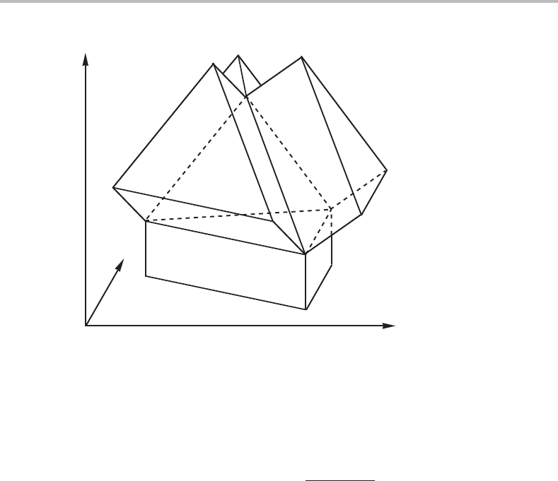
In a binary system there are three independent potential axes. If they are all replaced
by molar axes, all the phase fields become three-dimensional and the invariant four-
phase equilibrium expands into a tetrahedron. This is demonstrated by Fig. 9.4 which
corresponds to the central region of Fig. 8.11.
It was emphasized that the topology of potential phase diagrams is very simple and
each geometrical element is a phase field. A phase diagram with only molar axes has
a relatively simple topology. All the phase fields have the same dimensionality as the
diagram itself. For the unary system in Fig. 9.2 all the phase fields have two dimensions
and for the binary system in Fig. 9.4 they have three dimensions.
Exercise 9.1
Suppose one studies the total vapour pressure of a liquid mixture of two metals, A and
B, at a constant temperature. One finds that the total vapour pressure increases if more
Bisadded to the mixture. Show whether the vapour or the liquid is richer in B.

9.2 Sets of conjugate pairs containing molar variables 189
before
(a) (b)
vapour
vapour
liquid
liquid
PP
z
B
µ
B
after
Figure 9.5 Solution to Exercise 9.1.
Hint
At constant T, the P, µ
B
potential phase diagram will be two-dimensional. Sketch it
using µ
A
as the dependent potential variable. Remember that the conjugate composition
variable to µ
B
would then be z
B
= N
B
/N
A
. High pressure should favour the liquid, being
much denser than the vapour.
Solution
The construction (Fig. 9.5) shows that the vapour would be richer in B than the liquid if
measured relative to A.
9.2 Sets of conjugate pairs containing molar variables
A molar variable can easily be introduced in the stability condition, Eq. (6.28), by dividing
X
b
with the quantity used to define the size of the system because that quantity is kept
constant. Expressing the size by N,weget for instance,
∂Y
b
∂ X
b
m
Y
c
,X
d
m
= N ·
∂Y
b
∂ X
b
Y
c
,X
d
> 0. (9.5)
However, with this measure of size the Gibbs–Duhem relation gives
S
m
dT − V
m
dP +
x
i
dµ
i
= 0, (9.6)
where one of the x
i
is dependent on the others because
x
i
= 1. Choosing x
1
as the
dependent one, we obtain x
1
= 1 −
2
x
i
,
− dµ
1
= S
m
dT − V
m
dP +
2
x
i
d(µ
i
− µ
1
). (9.7)
Then it is logical to regard µ
1
as the dependent potential but the consequence is that the
conjugate variable to x
i
is no longer µ
i
but (µ
i
− µ
l
).
If we instead measure the size with the amount of a certain component, N
1
, then we
obtain the form given by Eq. (9.2),
− dµ
1
= S
m1
dT − V
m1
dP +
2
z
i
dµ
i
. (9.8)

190 Molar phase diagrams
Table 9.1 Sets of conjugate pairs of independent state variables using
molar quantities defined by dividing with N
i
T, S
m
−P, V
m
2
(µ
i
− µ
1
), x
i
T, (TS
m
− PV
m
)/T −P/T, TV
m
2
(µ
i
− µ
1
), x
i
T/P, PS
m
P, (TS
m
− PV
m
)/P
2
(µ
i
− µ
1
), x
i
−1/T, U
m
−P/T, V
m
2
(µ
i
− µ
1
)/T, x
i
−1/T, H
m
−P, V
m
/T
2
(µ
i
− µ
1
)/T, x
i
−P/T, H
m
/P −1/P, PU
m
/T
2
(µ
i
− µ
1
)/T, x
i
T/P, S
m
−1/P, U
m
2
(µ
i
− µ
1
)/P, x
i
−1/T, TU
m
/P −T /P, F
m
/T
2
(µ
i
− µ
1
)/P, x
i
T, S
m
/P −1/P, F
m
2
(µ
i
− µ
1
)/P, x
i
In this way one may keep µ
i
but its conjugate variable is z
i
= N
i
/N
j
and S
m1
and V
m1
are also defined by dividing with N
1
.
Sometimes it is convenient to measure the size as the total content of more than one
component, e.g. of those which do not easily evaporate. Suppose they are the first k
components. Using u
1
= 1 −
k
2
u
i
we obtain
S
m(1...k)
dT − V
m(1...k)
dP +
c
2
u
i(1...k)
dµ
i
= 0 (9.9)
−dµ
1
= S
m(1...k)
dT − V
m(1...k)
dP +
k
2
u
i(1...k)
d(µ
i
− µ
1
)+
c
k+1
u
i(1...k)
dµ
i
= 0.
(9.10)
where the S, V and u variables are defined in Section 4.3.
These three methods of measuring the size of the system can be applied to all the
rows in Table 3.1.Wemay thus construct Tables 9.1, 9.2 and 9.3 for the sets of conjugate
potentials and molar variables. Each row defines a set of conjugate variables and each
pair can be used to construct a stability condition if the variables to be kept constant are
taken from the same set. There is an important difference from Table 3.1 which gave
sets of conjugate pairs related by the Gibbs–Duhem relation. A dependent potential has
now been eliminated using the Gibbs–Duhem relation and the new tables contain one
pair less and give sets of pairs of independent variables.

9.2 Sets of conjugate pairs containing molar variables 191
Table 9.2 Sets of conjugate pairs of independent state variables using
molar quantities defined by dividing with N
1
T, S
m
1
−P, V
m1
2
µ
i
, z
i
T, (TS
m1
− PV
m1
)/T −P/T, TV
m1
2
µ
i
, z
i
T/P, PS
m1
P, (TS
m1
− PV
m1
)/P
2
µ
i
, z
i
−1/T, U
m1
−P/T, V
m1
2
µ
i
/T, z
i
−1/T, H
m1
−P, V
m1
/T
2
µ
i
/T, z
i
−P/T, H
m1
/P −1/P, PU
m1
/T
2
µ
i
/T, z
i
T/P, S
m1
−1/P, U
m1
2
µ
i
/P, z
i
−1/T, TU
m1
/P −T /P, F
m1
/T
2
µ
i
/P, z
i
T, S
m1
/P −1/P, F
m1
2
µ
i
/P, z
i
Table 9.3 Sets of conjugate pairs of independent state variables using molar quantities defined by
dividing with N
1
+ N
2
T, S
m12
−P, V
m12
(µ
2
− µ
1
), u
i(12)
3
µ
i
, u
i(12)
T, (TS
m12
− PV
m12
)/T −P/T, TV
m12
(µ
2
− µ
1
), u
i(12)
3
µ
i
, u
i(12)
T/P, PS
m12
P, (TS
m12
− PV
m12
)/P (µ
2
− µ
1
), u
i(12)
3
µ
i
, u
i(12)
−1/T, U
m12
−P/T, V
m12
(µ
2
− µ
1
)/T, u
i(12)
3
µ
i
/T, u
i(12)
−1/T, H
m12
−P, V
m12
/T (µ
2
− µ
1
)/T, u
i(12)
3
µ
i
/T, u
i(12)
−P/T, H
m12
/P −1/P, PU
m12
/T (µ
2
− µ
1
)/T, u
i(12)
3
µ
i
/T, u
i(12)
T/P, S
m12
−1/P, U
m12
(µ
2
− µ
1
)/P, u
i(12)
3
µ
i
/P, u
i(12)
−1/T, TU
m12
/P −T /P, F
m12
/T (µ
2
− µ
1
)/P, u
i(12)
3
µ
i
/P, u
i(12)
T, S
m12
/P −1/P, F
m12
(µ
2
− µ
1
)/P, u
i(12)
3
µ
i
/P, u
i(12)

192 Molar phase diagrams
3000
(a) (b)
6
4
log(P
N
2
) (bar)
2
0
−60
log(x
N
)
L/α
α/L
α/Mo
2
N
Mo
2
N/α
α
L/Mo
2
N
Mo
2
N/L
1000
L
500
100
Mo
2
N
10
1 bar
2500
2000
T (K)
1500
1000
0 0.5
x
N
Figure 9.6 See Exercise 9.3.
Exercise 9.2
At the end of Section 6.6 we found that the stability limit in a binary solution is g
22
= 0.
Show how this condition can be obtained from the list of conjugate variables presented
in Table 9.1.
Hint
The index 2 in g
22
indicates a derivative with respect to x
2
, with x
1
as a dependent
variable. Thus, one should use a set of conjugate variables containing x
2
.
Solution
From the first row of Table 9.1 we can formulate the condition (∂(µ
2
− µ
1
)/∂x
2
)
T,P,N
=
0. However, x
1
is a dependent variable and µ
2
− µ
1
= ∂G
m
/∂x
2
and our stabil-
ity condition can be expressed as ∂
2
G
m
/∂x
2
2
= 0 and g
22
is the notation for that
derivative.
Exercise 9.3
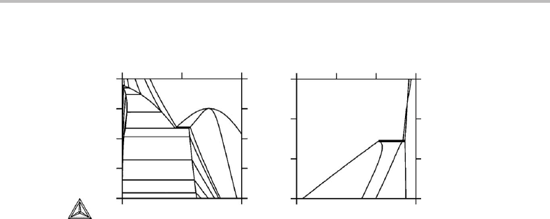
Two diagrams of the Mo–N system are presented in Fig. 9.6.How would you interpret
them?
Hint
In diagram (a) notice that the phase field for the gas is not included but isobars for the N
2
gas are given. In order to interpret diagram (b) it is helpful first to construct a T, log P
N
2
diagram and then replace the T axis with a log x
N
axis.
Solution
Diagram (a) above is a T, x
N
diagram at 1 bar. The lines for various N
2
pressures should
be understood as isoactivity lines for N expressed as P
N
2
of a gas which is not present.

9.3 Phase boundaries 193
6
(a) (b)
6
4
log(P
N
2
) (bar)
2
0
−60
log(x
N
)
L/α
α/L
α/Mo
2
N
Mo
2
N/α
L/Mo
2
N
Mo
2
N/L
α
L
4
2
log(P
N
2
) (bar)
0
3000 10002000
T (K)
Mo
2
N
Figure 9.7 Solution to Exercise 9.3.
X
m
j
1
(a) (b)
X
m
k
Figure 9.8 (a) Elementary unit of a phase diagram with two molar axes. (b) Topological
equivalence.
Using these values of P
N
2
it is easy to construct a T , log P
N
2
diagram (see Fig. 9.7(a)).
For convenience, we shall make T the abscissa. Next we shall introduce x
N
(with a
logarithmic scale) instead of T, i.e. a molar quantity instead of a potential. The two-
phase fields will open up but there may be overlapping because the new variable, x
N
,is
not conjugate to the old one, T. As an example, the α + L field falls inside the α + Mo
2
N
field.
9.3 Phase boundaries
Since all the phase fields in a molar diagram have the same dimensionality as the diagram
has axes, it is evident that all other geometrical elements, surfaces, line and points in
a three-dimensional diagram, are not phase fields. They separate phase fields and may
be called phase boundaries. When discussing the topology of a molar phase diagram
in terms of the phase boundaries, it is possible and convenient to choose a smaller
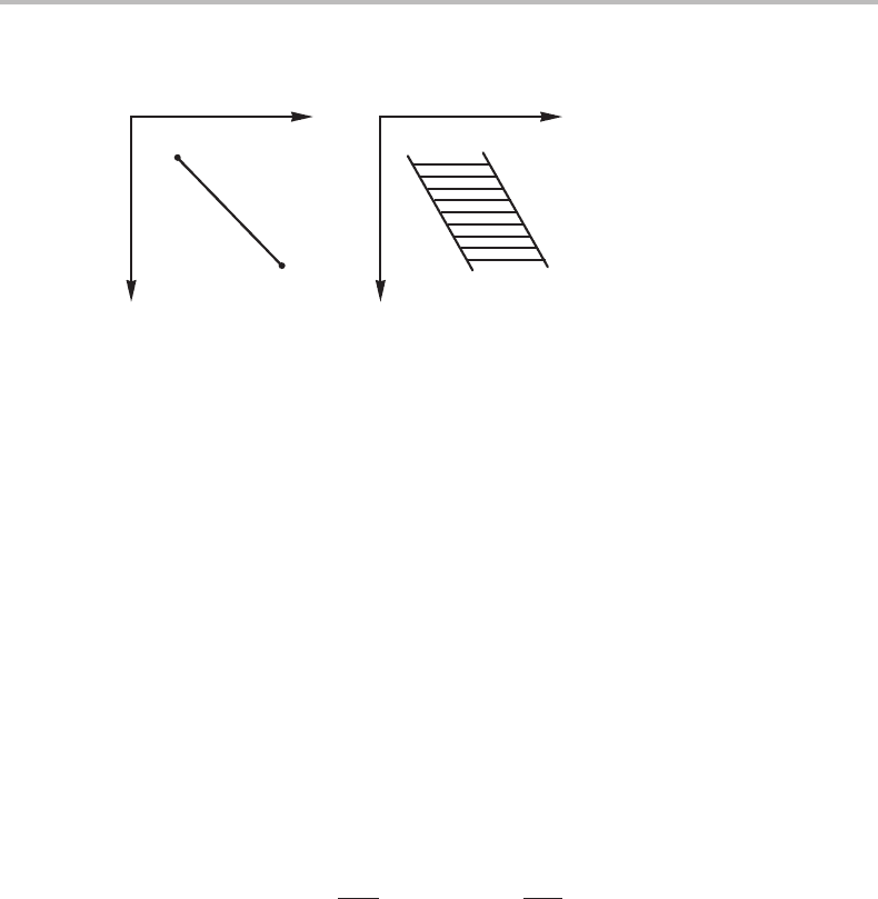
elementary unit than a phase field. A smaller unit is shown in Fig. 9.8(a) and it is
composed of four linear phase boundaries meeting at a point. Topologically it may be
represented by two intersecting lines as shown in Fig. 9.8(b).Any complicated two-
dimensional phase diagram with molar axes is composed of such units.

194 Molar phase diagrams
X
m
m
1
X
m
j
1
X
m
k
Figure 9.9 Elementary unit of a phase diagram with three molar axes.
It can be seen by inspection of the three-dimensional diagram in Fig. 9.4, that it
is possible to divide it into four topologically identical, elementary units, each one
composed of a point where eight phase fields meet, although only four of them are shown.
Six linear phase boundaries radiate from these points. They are all shown for the β and
δ points. Topologically, this elementary unit can be represented by three intersecting
planes as shown in Fig. 9.9. Evidently, the topology of a complicated three-dimensional
molar diagram can be represented by a system of intersecting surfaces.
When studying two-dimensional molar diagrams, Masing [11] observed that the num-
ber of phases in the phase fields changes by one unit when one crosses a linear phase
boundary. This is easily verified by inspection of Fig. 9.2(d). Masing’s rule was later
generalized by Palatnik and Landau [12]who gave it the following form
D
+
+ D
−
= r − b, (9.11)
where D
+
and D
−
are the number of phases that appear and disappear, respectively, as
one crosses a phase boundary of dimensionality b, and r is the number of axes in the
molar diagram. This rule may be referred to as the MPL boundary rule, after Masing,
Palatnik and Landau.
It may be added that phase boundaries sometimes have special names. The boundary
between a liquid phase and a liquid + solid phase field is called the liquidus and the
corresponding boundary for the coexistingsolid phase is called the solidus. The boundary
between a solid and the two-phase field with another solid is sometimes called the solvus.
Exercise 9.4
In the central region of Fig. 9.4 there is a tetrahedron, representing a four-phase field.
Apply the MPL rule in order to find how many phases there are outside the α − β line
and outside the β point.
Hint
There are only four phases in the system and D
+
must be zero when we move out from
the four-phase field because there is no new phase that can be added.
