Heinrich J.G., Aldinger F. (Eds.) Ceramic Materials and Components for Engines
Подождите немного. Документ загружается.


This Page Intentionally Left Blank
INTERNALLY COOLED MONOLITHIC
SILICON NITRIDE AEROSPACE COMPONENTS
Jonathan
E.
Best*, James
D.
Cawley*, Ramakrishna T, Bhatt** and Dennis
S.
Fox***
(*)
Materials Science and Engineering, Case Western Reserve University
10900 Euclid Avenue, Cleveland, Ohio 44106
(**)Army Research Laboratory Vehicle Tech. Dir., 21000 Brookpark Rd.
Cleveland, Ohio 44135
(***)
NASA Glenn Research Center, 21000 Brookpark Rd. Cleveland, Ohio 44135
ABSTRACT
A
set of rapid prototyping (RP) processes have been
combined with gelcasting to make ceramic aerospace
components that contain internal cooling geometry.
A
mold and core combination is made using a MM6Pro
(Sanders Prototyping, Inc.) and SLA-250/40
(3Dsystems, Inc.). The MM6Pro produces cores from
ProtoBuildTM wax that are dissolved in room
temperature ethanol following gelcasting. The
SLA-
250/40 yields epoxy/acrylate reusable molds. Parts
produced by this method include two types of
specimens containing a high density of thin long cooling
channels, thin-walled cylinders and plates, as well as a
model hollow airfoil shape that can be used for burner
rig evaluation of coatings. Both uncoated and mullite-
coated hollow airfoils has been tested in a Mach
0.3
burner rig with cooling air demonstrating internal
cooling and comfirming the effectiveness of mullite
coatings.
INTRODUCTION
The efficiency of a gas turbine engine
is
increased
by raising the turbine inlet temperature and the
maximum temperature is ultimately limited by material
properties. In order to approach service near
90%
of
their melting point, superalloy blades and vanes have
become elegantly engineered’. In part this is
microstructural, for example, the progression from
equiaxed to directionally solidified to single crystal and
the gamma gamma-prime strengthening. But of equal
importance is the development of coring technologies
that permit internal cooling and the application of
environmentally resistant coatings. The former allows
the surface temperature of the component to kept to a
maximum that is significantly below the ambient
whereas the latter mitigates the effects of oxidation and
other corrosion processes as well as providing a thermal
barrier.
Much of the work on producing ceramic materials
has focused of the development of material properties
such as resistance to thermal shock and oxidation, high
temperature strength and stiffness, and creep resistance.
And the results have been singularly successful.
In
particular, both commercial and research grades silicon
nitrides (usually alloys containing rare earth oxides
in
combination with aluminosilicates) are available which
can tolerate sudden quenches
in
excess of 1000°C, have
strengths greater than
800
MPa, and which tolerate
service operating temperatures up to 13OOOC. In-situ
reinforced silicon nitride formulations have been
developed with fracture toughnesses
in
excess of
8
MPadm.
The combination of such properties are
immediately suggestive of application in gas turbine
(and rocket) applications’. Furthermore, the
effectiveness of internal cooling has been demonstrated
by Tsuchiya et al’ who have shown that the
it
is
reasonable to for the surface temperature of silicon
nitride components in a
150OOC
environment to be kept
below 1300°C through the use of internal air cooling,
which require modest flows.
Engineering the surface is suggested by work that
has been done demonstrating the use of plasma-sprayed
mullite to produce thermal and environmental barrier
coatings on silicon carbide and silicon nitride4.
The work reported herein represents an effort to
develop a process strategy to prototype silicon nitride
parts capable of internal cooling that is robust and easy
to
implement. Conceptually, the process is quite
straightforward: molds and cores are produced by two
different commercial RP processes and assembled; a
gelcasting slurry is prepared and forced into the cavity
under low pressure; after gelling, the part is liberated
through a combination of dissolution to remove the
cores and diassembly to remove the reusable molds.
The resultant wet part is dried and fired via conventional
means. Details of the process are given elsewhere’.
Gelcasting is a process developed at Oak Ridge
National Laboratory6 and it is particularly amenable to
use with soft tooling, such as that produced by polymer-
based RP processes because only very low pressures are
employed. In fact, Jamalabad et al. suggested the use
of
gelcasting in fugitive molds sometime ago’. The
approach taken
in
this work differs
in
that a combination
of RP methods is used, the design of the molding system
is different, and that a process for setting the gel,
immersion
is
a poly(ethy1ene glycol)
(PEG),
is used
incorporated.
The particular implementation of gelcasting
used
in
this work uses water-soluble organic materials.
Two monomers are employed: methacrylamide (MAM)
which polymerizes as a linear chain and
N,N’-
463
methylenebisacrylamide (MBAM) which is a
crosslinker. Just prior to casting an initiator,
N,N,N’,N’-
tetramethylethylenediamine
(TEMED), and
a catalyst, ammonium peroxydisulfate (APS), are mixed
into the slurry to commence the gelation process.
Standard stereolithography was used to
produce reusable molds. A SLA250/40 was used to
build epoxy/acrylate parts that survived molding and
subsequent immersion in ethanol and PEG without
noticeable damage
or
distortion. Dozens of casts were
made using the same epoxy/acrylate parts.
The Sanders Prototyping process was used to
produce cores and mold lines which were dissolved,
after casting, by soaking in room temperature ethanol
for several hours. A ModelMaker MM6Pro was used.
The Sanders process employs two materials to !kilt a
part. The actual part is built out of a “green wax”
(ProtoBuildTM) and the surrounding supports are built
out of a “red wax” (ProtoSupportTM). The waxes are
melted and each layer of the part is deposited using two
separate ink jets to spray droplets. A mechanical
grinder levels off each layer to the correct thickness.
These process steps continue until the entire part is
built. Upon completion the red supporting wax can be
selectively removed by heating to 40-50°C in a VS-0
bath. Beyond the fact that the green wax can be
dissolved with ethanol at room temperature, this method
is particularly suited to the production of cores
or
small
characteristic dimension
or
requiring fine details.
All CAD work was carried out using Rhino3D
(Robert McNeel and Associates) a NURBS package that
runs on PentiumTM class PCs.
PROCEDURE
Three types of parts were built. The first was a
reverse-engineered model airfoil shape based on
archival superalloy parts left over from the original
thermal barrier coating development program at NASA
Lewis Research Center (now NASA Glenn Research
Laboratory). The part allows internal cooling and was
readily coated with plasma sprayed mullite.
The other
two were demonstration parts to permit the a critical
evaluation of the possibility
for using thin cooling
channels of long length within the walls
of
thin-walled
plates and cylindrical sections.
In initial experiments, molds were entirely
epoxy/acrylate and a mold release was used to effect
separation of the gelled part from the mold. Although
often successful, distortion due to demolding stresses
was enough of a nuisance that soluble mold linings were
developed and used with great success. Mold linings
were made by the exact same process as the cores and
so
were simultaneously removed.
The net result is that
the space filled by the slurry was entirely bounded by
surfaces made up of the Protobuild material. This was
true for all of the parts discussed.
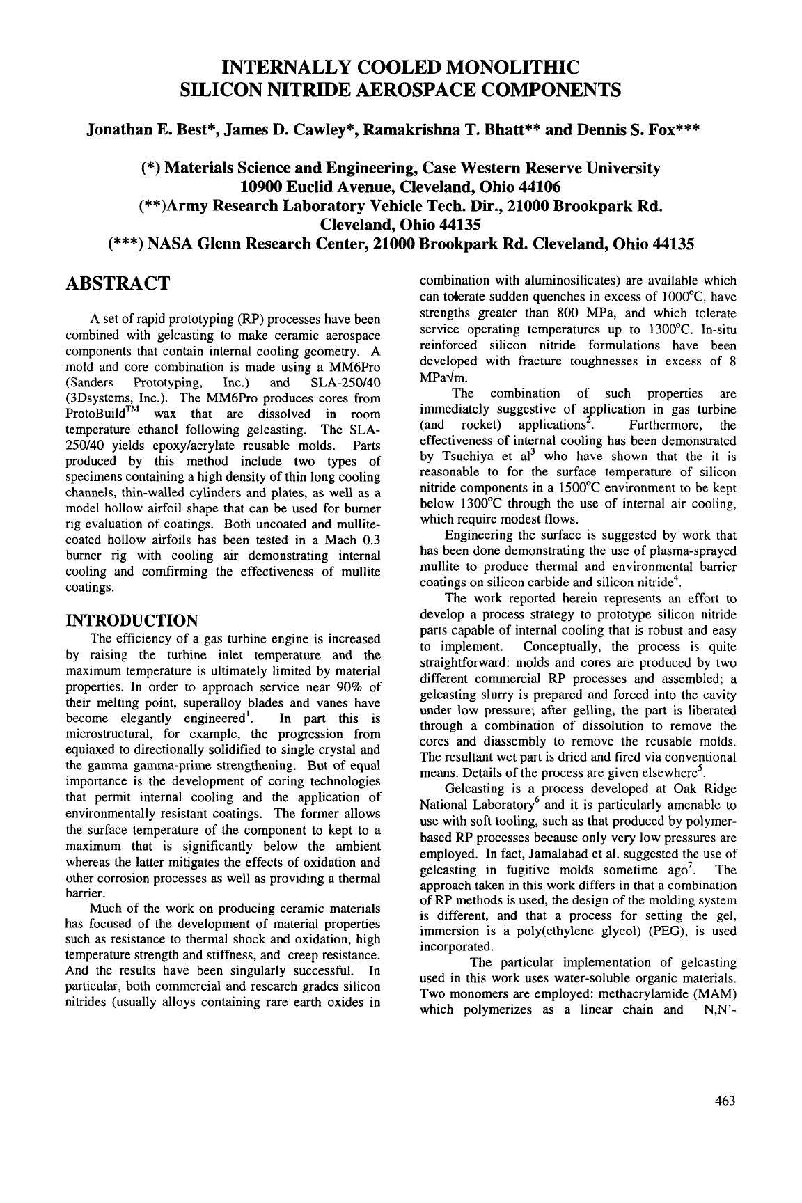
Figure 1 shows the CAD representation of the
molding system used to make the thin-walled internally
cooled hollow cylinder. Similar mold systems are used
for other components. In practice, the joints of the
assembled mold were sealed with a soft patching wax
(Kindt-Collins) and held together with teflon tape as
needed. After the casting has gelled, the entire mold is
immersed in ethanol to dissolve the wax components of
the molds. Leachable paths are designed such that all
the wax parts are connected to the external surface. The
wax linings and cores dissolve away
in
a few hours.
The part is then submerged
in
PEG for drying.
As
the
gating structure would restrict drying shrinkage creating
undesirable stresses within the part, it is trimmed from
the part prior to drying. After the part is dried, typical
ceramic firing procedures are employed. The process
steps are illustrated in Fig.
2
using a different mold/core
set to illustrate each.
FABRICATED PARTS
The results
of
the molding process as well
represented by the results shown in Fig. 3 for the
cylinder. The cast part contains some flashing that must
be manually removed, but the overall shape and size is
accurate and the high density of small diameter holes
produced by the cores are excellent. The pathway of the
cooling holes is visible in the fired piece because of the
locally thin walls. Very similar results were obtained
with the flat plate.
The simulated airfoil specimen is documented
in
Figs. 4 and
5.
Figure 4 illustrates the results
of
the
reverse engineering process and Fig.
5
shows the
resultant silicon nitride version, which was an excellent
geometrical match for the original casting.
Mach 0.3 jet fuel burner rig testing was
conducted on superalloy, uncoated silicon nitride and
mullite-coated silicon nitride specimens. A typical test
condition is illustrated in the photograph appearing
in
Fig. 6. Quantitatively results indicate that cooling air
produced the expected comparable reductions
in
surface
temperature, up to 1 30°C for flowrates of approximately
1.5 lit/s.
CONCLUSIONS
The fabrication of internally cooled monolithic
silicon nitride aerospace components has been
demonstrated. Gelcasting coupled with rapid
prototyping technology allows for the production
of
these components which range from thin-walled shapes
with cooling channels to simpler hollow shapes. The
internal geometry of these parts is made possible by wax
cores produced by the Sanders Prototyping process,
which can be dissolved from wet gelcast parts with
ethanol. This technique brings the same flexibility
of
shape forming associated with metal casting to the
realm of ceramics processing. A hollow silicon nitride
airfoil produced with this process has been tested with
cooling air
in
a Mach 0.3 burner rig. Cooling air
reduced the surface temperature up to 130°C below the
uncooled condition
of
1 185OC.
464
ACKNOWLEDGEMENTS
Z.
Liu, CWRU, was of enormous help in general
ceramic processing and rapid prototyping. R. Babuder,
CWRU/NASA, was similarly invaluable in his help
with binder burnout and firing. Mike Cuy, NASA,
assisted with the burner rig testing. The work was
funded under NASNCWRU Cooperative Agreement on
Ceramic Processing Grant
#
NAS3-404.
REFERENCES
1.
2.
3.
4.
5.
6.
7.
C.
T.
Sims, “A History of Superalloys for
Superalloy Metallurgists,” pg. 399 in
Superalloys
1984,
edited by M. Gell, C.
S.
Kortovich, R. H.
Bricknell, W. B. Kent, and
J.
F.
Radavich, AIME,
1984.
Pollinger, J.P., Progress in fabrication of silicon
nitride structural components for turbomachinery
applications. ASME Paper 96-GT-347.
Tsuchiya, T., Furuse, Y., Yoshino,
S.,
Chikami,
R.,
Tsukagoshi,
K.,
Mori, M., Development of air-
cooled ceramic nozzles for a power generating gas
turbine. ASME Paper 95-GT-105.
K. N. Lee and
R.
A. Miller, “Development and
Environmental Durability of Mullite and
MulliteNSZ Dual Layer Coatings for Sic and
Si3N4 Ceramics,”
Surface and Coatings
Technology,
86-87
[
1-31 142-8 (1996).
J.
E.
Best, J. D. Cawley,
R.
Bhatt, and D. Fox,
“Fabrication and Testing of Internally Cooled
Monolithic Silicon Nitride Aerospace
Components,
J.
Am. Ceram. Soc.,
submitted.
0.0.
Omatete, M.
A.
Janney,
S.
D. Nunn,
“Gelcasting: from Laboratory Development toward
Industrial Production.
Journal of the European
Ceramic Society
17
(1997) 407-413.
Jamalabad,
V.R.,
Whalen, P.J., Pollinger, J.,
“Gelcast molding with rapid prototyped fugitive
molds,”
,
pp. 71-78 in
Proceedings of the Solid
Freeform Fabrication Symposium,
ed.
D.L.
Bourell, J.J. Beaman, H.L. Marcus,
R.
H.
Crawford, J. W. Barlow. The University of Texas
at Austin, Austin, Texas, 1996.
465
I
\
1
/
Figure
1
shows the
CAD
rendition of the assembly of the thin-walled internally cooled cylinder mold system.
The individual parts can be seen in the center overview from right to left: inner gating, inner lining, core half,
outer lining half, outer gating half. The design feature are highlighted numerically:
1)
registration features,
2)
slurry casting tube,
3)
bottom filling tray,
4)
flow path slats in core,
5)
overflow space,
6)
gate removal is
accomplished by cutting along this plane,
7)
uppermost of three slots for dissolution
of
outer lining, and
8)
leachable ethanol path for core dissolution (square cutouts are obsolete flow paths).
466
Figure
2
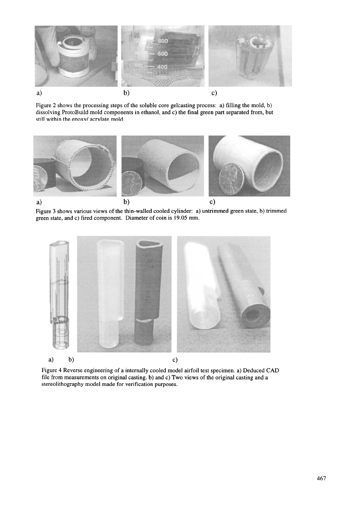
shows the processing steps of the soluble core gelcasting process: a) filling the mold, b)
dissolving ProtoBuild mold components in ethanol, and c) the final green part separated from, but
still
within
the
enoxv/
acrvlate
mold.
a)
b)
c)
Figure
3
shows various views of the thin-walled cooled cylinder: a) untrimmed green state, b) trimmed
green state, and c) fired component. Diameter of coin is
19.05
mm.
a)
b)
c>
Figure
4
Reverse engineering of a internally cooled model airfoil test specimen. a) Deduced CAD
file from measurements on original casting.
b)
and c) Two views of the original casting and a
stereolithography model made
for
verification purposes.
467
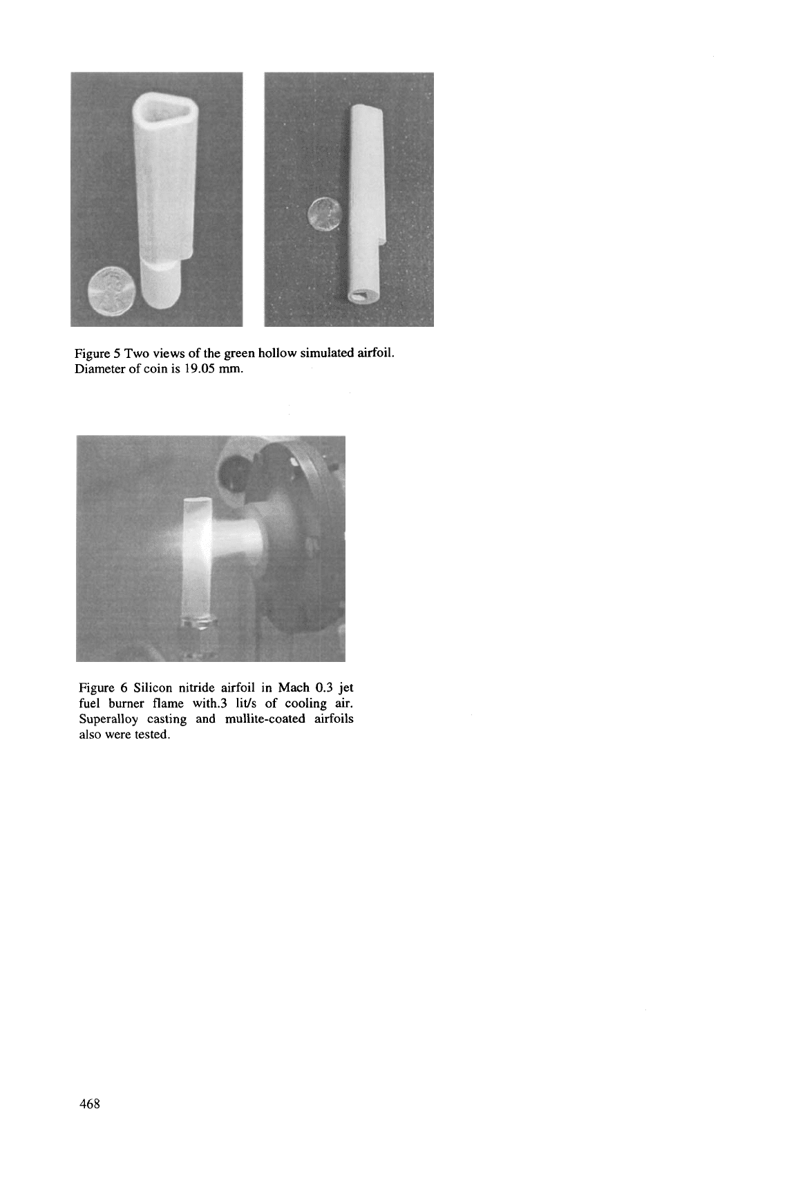
Figure
5
Two views of the green hollow simulated airfoil.
Diameter of coin is
19.05
mm.
Figure
6
Silicon nitride airfoil in Mach
0.3
jet
fuel burner flame with.3 lids of cooling air.
Superalloy casting and mullite-coated airfoils
also were tested.
468
PREPARATION AND HIGH TEMPERATURE STRENGTH
OF
G&A1209/MgO COMPOSITES
M. Shimada,
T.
Sakamoto and
H.
Yamane
Institute
for
Advanced Materials Processing, Tohoku University
Sendai 980-8577, Japan
ABSTRACT
Gd4Al~OdMg0 composite (MgO:
85
~01%) was
prepared from the mixed powders of Gd203,
A1203
and
MgO at
1600
"C
for
5
h in air. The relative density of
the composite was 99.1%. The X-ray powder diffraction
pattern of the composite was identified by the mixture of
Gd4A1209 and MgO.
No
other peaks were observed. The
composite had a uniform microstructure with grain sizes
of
1
=
2 pm for Gd4AlZOYand of about 4 pm for MgO.
A
bending strength of 400 MPa measured at 1100
"C
on
cooling from 1400
"C
was
1.6
times higher than that
measured at
1100
"C
on heating. This could be explai-
ned by the transformation toughening mechanism of the
high temperature phase Gd4Al2aat
110
"C
cooling.
INTRODUCTION
Recently, there has been a great effort to overcome
the intrinsically brittle nature of ceramics in order to
apply ceramic materials to engineering purposes. Since
the fracture toughness of ceramic materials is not high
enough, their use under high stress is limited. It is highly
desirable to improve the mechanical properties of ce-
ramic materials. Transformation toughening is one
effective approach
to
improving fracture toughness and
fracture strength of brittle ceramics. Transformation
toughening requires the stress-induced martensitic trans-
formation of particles, as well
known
in tetragonal zir-
conia ceramics (1). The main purpose of our study
is
to
find new oxide ceramics with stress induced phase trans-
formation.
Rare-earth aluminate,
%A1209
(R
rare-earth ele-
ment) is monoclinic with space group P2Jc at room
temperature
(2).
Yamane et.
Al.
(3) reported that
YdA11Q showed a reversible thermal phase transforma-
tion from low temperature monoclinic
to
high tempera-
ture monoclinic phases at 1377
"C.
The results of high-
temperature X-ray powder diffraction showed that the
unit cell volume of the high temperature phase Y4A1209
measured at 1400
"C
on cooling from 1450
"C
was
0.5%
smaller than that of the low-temperature phase at the
same temperature of 1400
"C
on heating from room
temperature (3). This volume change was in accordance
with the results of dilatometry. The phase transformation
of YdA1109 was concluded
to
be diffusionless by com-
parison
of
the crystal structures of the high- and low-
temperature phases determined by high-temperature
neutron diffraction (4). Gd~A1209 showed a reversible
thermal phase transformation and thermal hysteresis at
around
1100
"C
is about 200
"C
lower than that of
y4AlZa.
The present study attempts to stabilize the high-
temperature phase of Gd4A1209 by preparing composites
with MgO and examines the effect of phase transformation
toughening by measuring the high temperature fracture
strength.
EXPERIMENTAL
Powders of Gd203,
AlZ03
and MgO were used as
starting materials. These powders were weighed in the
appropriate proportion
of
G&A1209 and
15
vol%
Gd4Al209/85 vol% MgO and mixed in a plastic vessel
for 24 h by a wet ball milling with ethyl alcohol and
alumina balls. After drying at
80
"C
for
5
h in air, the
mixed powders were uniaxially pressed at 30 MPa, and
then isostatically pressed at 200 MPa
to
form pellets
(5x30~50 mm). The compact pellets were sintered at
1600
"C
for
5
h in air. The sintered pellets were cut into
rectangular coupons 2x4~20
mm.
The crystal structure
was studied by X-ray diffraction
(XRD).
The mic-
rostructure was observed by scanning electron micros-
copy (SEM). The thermal behaviour of Gd4A1109 and
Gd4AlZO&ig0 composites was characterized from
room temperature to 1500
"C
by high temperature
XRD
and thermal mechanical analysis (TMA). The bending
strength of Gd4A120&lg0 composites was measured
from room temperature
to
1400
"C
by a three-point
bending test with a crosshead sped of
0.5
mm/min and a
span length of
10
mm.
RESULTS
AND
DISCUSSION
The X-ray powder diffraction pattern of
Gd4A120&ig0 composite
(85
vol% MgO) was identi-
fied by the mixtures of Gd4A12OY and MgO phases.
No
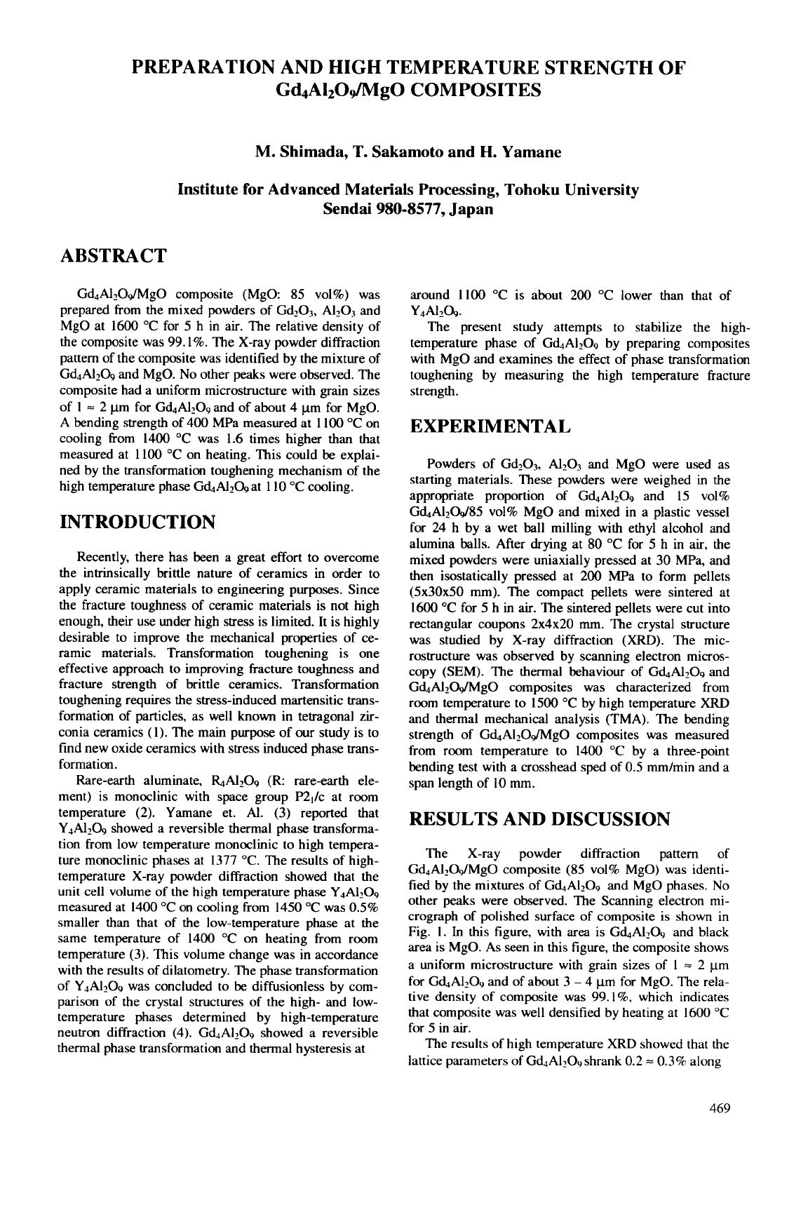
other peaks were observed. The Scanning electron mi-
crograph of polished surface of composite is shown in
Fig.
1.
In
this figure, with area is Gd4Al2a and black
area
is
MgO. As seen in this figure, the composite shows
a uniform microstructure with grain sizes of
1
=
2 pm
for Gd4A12O9 and of about
3
-
4
pm
for MgO. The rela-
tive density of composite was
99.l%,
which indicates
that composite was well densified by heating at
1600
"C
for
5
in air.
The results of high temperature XRD showed that the
lattice parameters
of
Gd4Al2O9shrank
0.2
=
0.3%
along
469
the c axis at the phase transformation fiom the low-
temperature phase. Since the
XRD
patterns of high-
temperature phase was similar with those of low-
temperature phase, it is considered that the crystal struc-
ture of high-temperature phase belongs to a monoclinic
structure. Anisotropy of thermal expansion was ob-
served below the phase transition temperature. The av-
erage thermal expansion of the
a
axis was about twice as
large as that of the
c
axis.
Fig 1 Polished surface of G&A120&lg0 composite
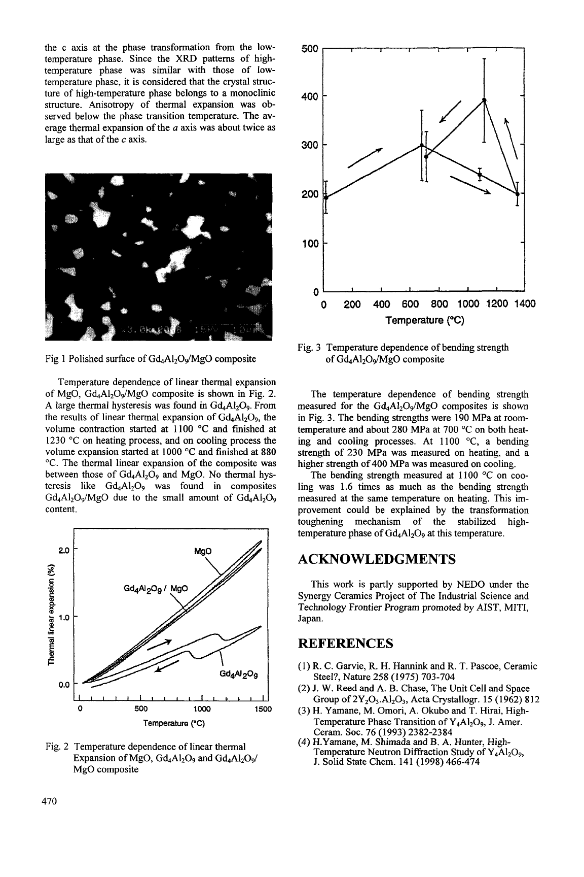
Temperature dependence of linear thermal expansion
of
MgO, Gd4A1209/Mg0 composite is shown in Fig. 2.
A
large thermal hysteresis was found in Gd4A1209. From
the results of linear thermal expansion of Gd4A1209, the
volume contraction started at 1100 "C and finished at
1230 "C on heating process, and on cooling process the
volume expansion started at 1000
"C
and finished at
880
"C. The thermal linear expansion
of
the composite was
between those
of
G&A1209 and MgO. No thermal hys-
teresis like Gd4A1209 was found in composites
Gd4A1209/Mg0 due to the small amount of Gd4A1209
content.
I
I
I
I
I
I
I
I
1
I
I
I
I.
I
I
I1
0
500
1000
1500
Temperature
('C)
Fig. 2 Temperature dependence of linear thermal
Expansion of MgO, Gd4A1209 and
Gd.+41209/
MgO composite
500
I
I
I
I
I
I
I
400
300
200
loot
0'
I
I
I
I
I
I
0
200
400
600
800
1000
1200
1400
Temperature
("C)
Fig. 3 Temperature dependence of bending strength
of Gd4A120&lg0 composite
The temperature dependence of bending strength
measured for the Gd4A1209/Mg0 composites is shown
in Fig. 3. The bending strengths were 190 MPa at room-
temperature and about 280 MPa at 700 "C on both heat-
ing and cooling processes. At 1100 "C, a bending
strength of 230 MPa was measured on heating, and a
higher strength of 400 MPa was measured on cooling.
The bending strength measured at
1
100 "C on coo-
ling was 1.6 times as much as the bending strength
measured at the same temperature
on
heating. This im-
provement could be explained by the transformation
toughening mechanism of the stabilized high-
temperature phase
of
G&A1209 at this temperature.
ACKNOWLEDGMENTS
This work is partly supported by NED0 under the
Synergy Ceramics Project of The Industrial Science and
Technology Frontier Program promoted by AIST, MITI,
Japan.
REFERENCES
(1) R. C. Garvie, R.
H.
Hannink and R. T. Pascoe, Ceramic
Steel?, Nature 258 (1975) 703-704
(2)
J. W.
Reed and A. B. Chase, The Unit Cell and Space
Group of 2Y203.A1203, Acta Crystallogr. 15 (1962)
812
H. Yamane, M. Omori, A.
Okubo
and
T.
Hirai, High-
Temperature Phase Transition of Y4A120g, J. Amer.
Ceram. SOC. 76 (1993) 2382-2384
H.Yamane,
M.
Shimada and B. A. Hunter, High-
Temperature Neutron Diffraction Study of Y4A1209,
J. Solid State Chem. 141 (1998) 466-474
470
CHARACTERIZATION
OF
IN SITU SIC-BN COMPOSITES
Guo-Jun Zhang* and Tatsuki Ohji
Synergy Ceramics Laboratory, National Industrial Research Institute
of
Nagoya,
Nagoya, Aichi
463-8687,
Japan
ABSTRACT
Sic-BN composites were prepared by in
situ reaction using Si,N4, B4C and
C
as
reactants. Adding Sic powder into the
reactants controlled the content of BN in the
composite. For comparison, monolithic Sic
and SIC-BN composites with the same phase
compositions were produced by conventional
process. The in situ process was advantageous
for obtaining better composites with fine grain
size, homogeneously and isotropically
distributed microstructures. The elastic
modulus decreased markedly with increasing
BN content and obeyed well both to the
exponential and polynomial rules. The bending
strength increased slightly with increasing BN
content up to 15 vol%, and then gradually
decreased; the decrease was accelerated above
35
~01%. The results were explained by a
percolation network formation of the BN
phase. The fracture toughness decreased with
increasing BN content. It can be excepted that
these in situ Sic-BN composites have
excellent mechanical strain tolerance and
thermal shock resistance.
INTRODUCTION
Silicon carbide (Sic) is a potential candi-
date material for structural applications at high
temperatures. In many cases of application
ceramic components are assembled with other
components made of metals to form a hybrid
structural part. The failure of such hybrid part
often occurs in the ceramic components at the
connecting section due to the mismatch of
thermal expansion coeffi-cients and elastic
strains in different materials. To avoid these
fractures, it is required that the elastic modulus
of Sic ceramic material is reduced. BN
ceramics, which shows very low elastic
modulus among ceramic materials, have been
widely used as the second phase to reduce the
elastic modulus and improve the thermal shock
resistance of monolithic ceramic materials,
such as in Si3N4-BN [l-31 and SIC-BN [4-61
composites. Unfortunately, the bending
strength of BN-containing composites
generally decreased with increasing the BN
content compared to the monolithic ceramics.
One of the main reasons is that the poor
sinteribility of BN affects densification
behavior of BN composite. The other is that
because BN is weak, BN agglomerates or large
BN particles/platelets may act as fracture flaws.
This means that BN dispersoids with fine
particle size and homogeneous distribution are
the key factors to obtain high strength compo-
sites. Reactions are also used to synthesize
BN-based composites. For example, Coblenz
and Lewis
[l]
used the in situ reactions of
Si3N4
+
B203, A1N
+
B203 or Si3N4
+
A1N
+
B,O, to produce SO2-BN, A1203-BN and
mullite-BN composites, respectively.
Kusunose et a1
[3]
prepared Si3N4/BN
nanocomposites by in situ formation of nano-
sized h-BN coated on a-Si3N4.particles with a
mixture of boric acid and urea in hydrogen gas.
In addition, in the Si-B-C-N system, Riedel et
a1
[7,8]
developed a silicoboron carbonitride
ceramic material, which is stable to 2000
OC,
from polymeric boron-containing
polysilylcarbidi-imide precursor.
By in situ process, one can generally
obtain composites with finer and more homo-
geneous microstructures, higher chemical and
microstructural stability at high temperature,
and better mechanical properties than the
conventionally processed ones. Recently the
authors proposed the following reaction
to
synthesize SIC-BN composite:
The weight percents of Sic and BN in the
obtained composite according to reaction (1)
are 54.79
%
and 45.21
%,
respectively, and the
volume percents are 46.29
%
and 53.71
%,
respectively. By adding Sic powder into the
reactants, the content of Sic in the composite
can be adjusted. Here the preparation of the in
situ
composites will be firstly introduced, then
the mechanical properties of the obtained
composites will be characterized.
Si3N4
+
B4C
+
2C
=
3SiC
+
4BN..
. .
.
.(
1)
EXPERIMENTAL PROCEDURE
The starting powders were Si3N4 (E-10
grade, Ube Industries, Japan), B4C (F1 grade,
47
1