Hearn E.J. Mechanics of Materials. Volume 1
Подождите немного. Документ загружается.

514.3
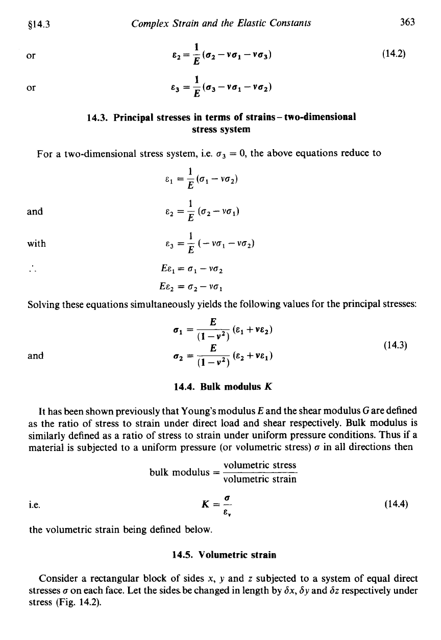
or
or
Complex
Strain and
the
Elastic Constants
1
E
-
-(az-val
-V63)
z-
E
E3
=
-
(63
-
vu1
-
vaz)
1
E
363
(14.2)
14.3. Principal stresses in terms
of
strains
-
two-dimensional
stress system
For a two-dimensional stress system, Le.
a3
=
0,
the above equations reduce to
1
E
1
E
1
E
E1
=
-
(crl
-
va2)
E2
=
-
(az
-
Vbl)
E3
=
-
(-
Val-
YO2)
and
with
..
=
a1
-
va2
EEZ
=
02
-
VO~
Solving these equations simultaneously yields the following values for the principal stresses:
and
(14.3)
14.4.
Bulk
modulus
K
It has been shown previously that Young’s modulus
E
and the shear modulus
G
are defined
as the ratio of stress to strain under direct load and shear respectively. Bulk modulus is
similarly defined as a ratio of stress to strain under uniform pressure conditions. Thus if
a
material is subjected
to
a uniform pressure (or volumetric stress)
0
in all directions then
volumetric stress
volumetric strain
bulk modulus
=
a
i.e.
K=-
E,
the volumetric strain being defined below.
14.5. Volumetric strain
(
14.4)
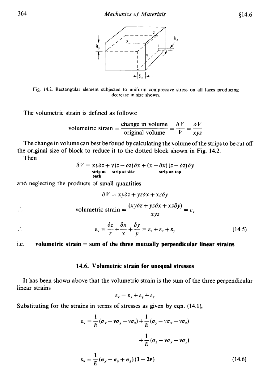
Consider a rectangular block of sides
x,
y
and
z
subjected to a system of equal direct
stresses
a
on each face. Let the sides be changed in length by
Sx,
6y
and
6z
respectively under
stress (Fig. 14.2).
364
Mechanics
of
Materials
914.6
Fig.
14.2.
Rectangular element subjected to uniform compressive stress
on
all faces producing
decrease
in
size
shown.
The volumetric strain is defined
as
follows:
change in volume
6V
SV
volumetric strain
= =-
=-
original volume
V
xyz
The change in volume can best be found by calculating the volume of the strips to be cut
off
Then
the original size
of
block to reduce it to the dotted block shown in Fig. 14.2.
sv
=
xysz
+
y(z
-
6Z)hX
+
(x
-
6x) (z
-
6z)sy
strip
at
strip
at
side
strip
on
top
back
and neglecting the products of small quantities
..
6
v
=
xysz
+
yzdx
+
xzsy
volumetric strain
=
=
E,
(xydz
+
yzsx
+
xzhy)
XYZ
..
(14.5)
i.e.
volumetric strain
=
sum
of
tbe three mutually perpendicular linear strains
14.6.
Volumetric strain
for
unequal stresses
It has been shown above that the volumetric strain is the sum of the three perpendicular
linear strains
E,
=
E,
+
Eg
+
E,
Substituting for the strains in terms of stresses as given by eqn. (14.1),
1
1
E E
1
E
E,
=
-
(a,
-
VbY
-
va,) +-(ay
-
va,
-
vaJ
+
-
(a,
-
Vb,
-
vay)
1
EV
=
~(u*+U,+u,)(l-2")
(14.6)
$14.7
Complex Strain and the Elastic Constants
365
It will be shown later that the following relationship applies between the elastic constants
E,
v
and
K,
Thus the volumetric strain may be written in terms of the bulk modulus as follows:
E=3K(1-2~)
(14.7)
This equation applies to solid bodies only and cannot be used
for
the determination
of
internal
volume
(or
capacity) changes
of
hollow vessels.
It may be used, however, for changes in cylinder
wall volume.
14.7.
Change
in
volume
of
circular
bar
A
simple application of eqn.
(14.6)
is to the determination of volume changes of circular
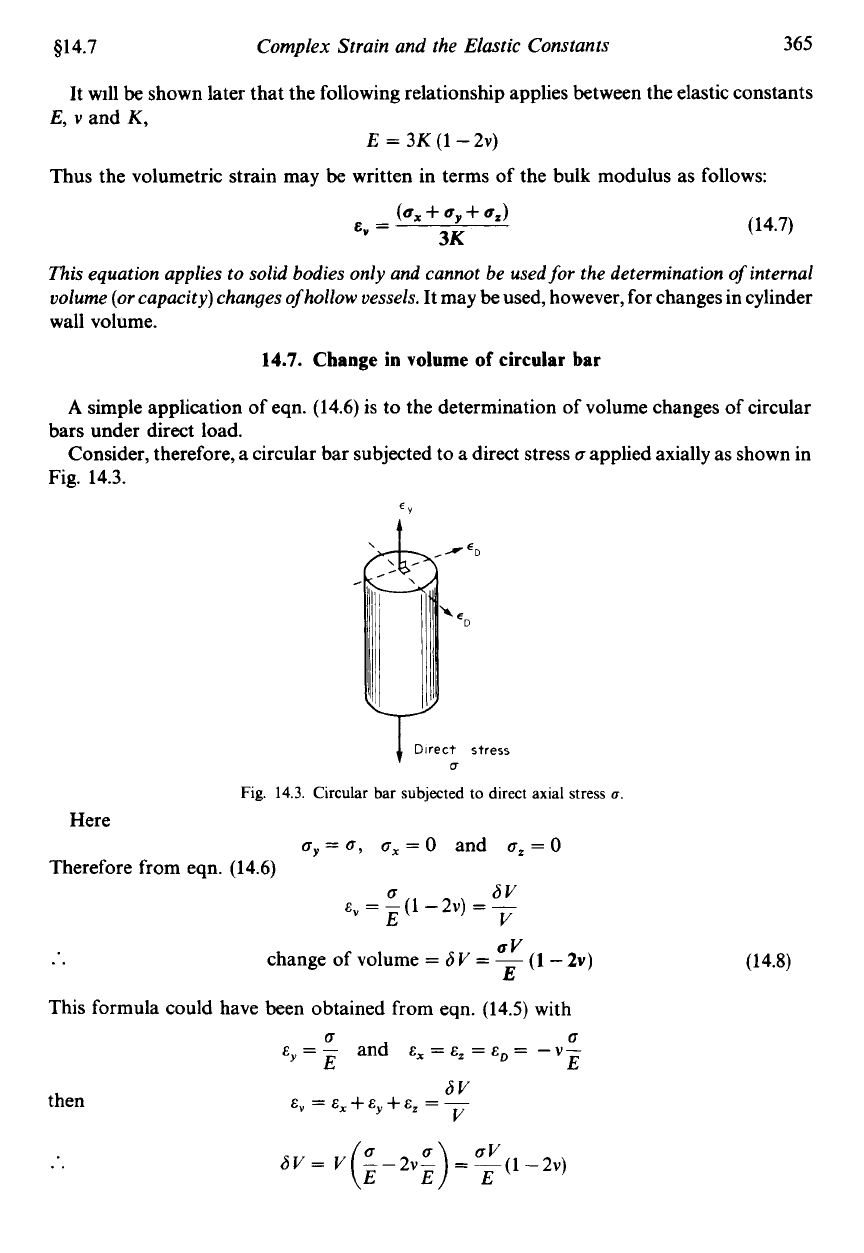
Consider, therefore, a circular bar subjected to a direct stress
6
applied axially as shown in
bars under direct load.
Fig.
14.3.
EY
*
%
c
Direct
stress
U
Fig.
14.3.
Circular bar subjected to direct axial stress
u.
cy=
6,
cx
=
0
and
0,
=
0
Here
Therefore from eqn.
(14.6)
6V
E,
=
-(1-2v)
=
-
E
V
6
UV
E
..
This
formula could have been obtained from eqn.
(14.5)
with
change of volume
=
6
V
=
-
(1
-
2v)
6
d
E,
=
-
and
E,
=
E,
=
E,,
=
-
v-
E
E
6V
V
then
E,=E,+E,+E,=-
(14.8)
366
Mechanics
of
Materials
$14.8
14.8.
Effect of lateral restraint
(a) Restraint in one direction only
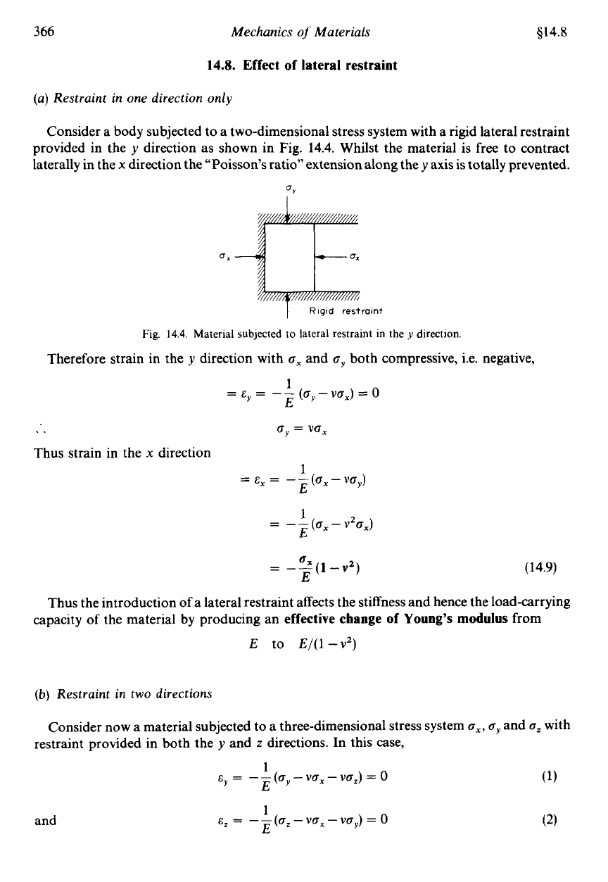
Consider a body subjected to a two-dimensional stress system with a rigid lateral restraint
provided in the
y
direction as shown in Fig.
14.4.
Whilst the material is free
to
contract
laterally in the
x
direction the “Poisson’s ratio” extension along they axis is totally prevented.
UY
I
I
Rigid
restraint
Fig.
14.4.
Material subjected to lateral restraint in the
y
direction.
Therefore strain in the
y
direction with
a,
and
oy
both compressive, i.e. negative,
1
’E
=E
=
--
(ay-va,)
=
0
..
a,
=
va,
Thus strain in the
x
direction
1
E
=
E,
=
--(a,
-
va,)
1
E
=
-
-
(a,
-
v%,)
(14.9)
Thus the introduction of a lateral restraint affects the stiffness and hence the load-carrying
capacity
of
the material by producing an
effective change of Young’s
modulus
from
E
to
E/(1
-v*)
(b)
Restraint in two directions
Consider now a material subjected to a three-dimensional stress system
a,, a,
and
a,
with
restraint provided in both the
y
and
z
directions. In this case,
(1)
(2)
1
’E
1
‘E
E
=
--(ay-va,-va,)
=o
E
=
--(a,-vo,-vay)=0
and
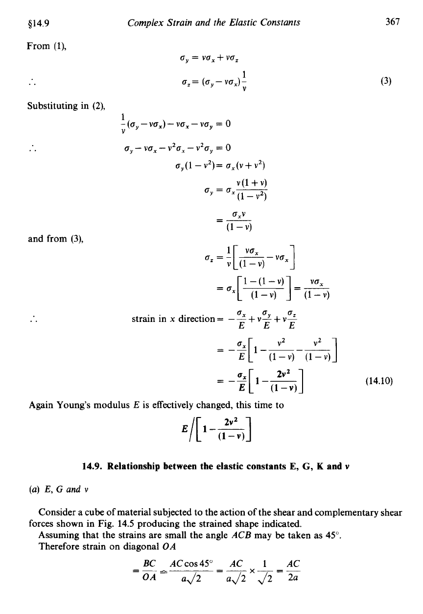
$14.9
Complex Strain and the Elastic Constants
From
(l),
..
6,
=
vox
+
voz
6,
=
(0,
-
vox)
-
1
V
Substituting in
(2),
1
-
(oy
-vox)
-
vox
-
Yoy
=
0
V
..
o,
-
vox
-
v20x
-
v20y
=
O
o,(l-v2)= o,(v+v2)
v(l
+v)
0,
=
6,-
(1
-
v2)
fJXV
=-
(1
-
v)
and from
(3),
..
cz=-
'[
--
vox
vox]
=ox[
(1-v)
]
(1-v)
v
(1
-v)
1
-
(1
-
v)
VOX
=-
ox
o
o
strain in
x
direction
=
-
-
+
v--li
+
v?
EEE
E
(1-V) (1-V)
367
(3)
(14.10)
Again Young's modulus
E
is effectively changed, this time to
14.9.
Relationship between the elastic constants
E,
G,
K
and
v
(a)
E,
G
and
v
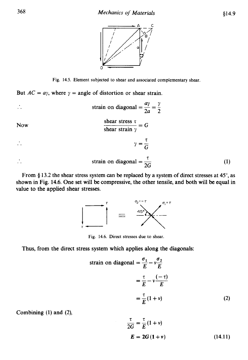
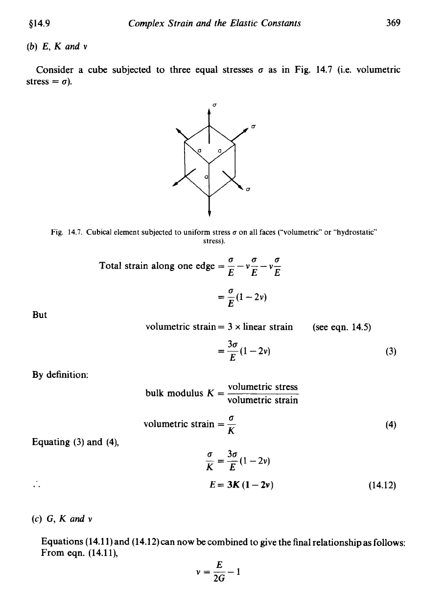
Consider a cube of material subjected to the action
of
the shear and complementary shear
Assuming that the strains are small the angle ACB may
be
taken as
45".
Therefore strain on diagonal OA
forces shown in Fig.
14.5
producing the strained shape indicated.
BC
ACcos45" AC
1
AC
OA-
ad2
a~2~~2=2a
=-A
=-
368
Mechanics
of
Materials
$14.9
Fig.
14.5. Element subjected
to
shear and associated complementary
shear.
But
AC
=
ay,
where
y
=
angle
of
distortion or shear strain.
..
Now
..
..
From
Q
aY
Y
strain on diagonal
=
-
=
-
2a 2
shear stress
z
shear strain
y
=G
z
y=-
G
t
strain on diagonal
=
-
2G
3.2
the shear stress system can
be
replaced by a system
of
direct stresses at
5",
as
shown in Fig. 14.6. One set will
be
compressive, the other tensile, and both will
be
equal in
value to the applied shear stresses.
u2=-r
/_I
~
-
4x=T
_-
r-
Fig.
14.6. Direct stresses due to
shear
Thus, from the direct stress system which applies along the diagonals:
01
02
strain on diagonal
=
--
v-
EE
(-4
V-
=--
EE
T
=
-(1
+v)
E
Combining (1) and
(2),
tz
-=-(1+v)
2G
E
E
=
2G(l+v)
(14.11)
$14.9
(b)
E,
K
and
v
Complex Strain and the Elastic Constants
369
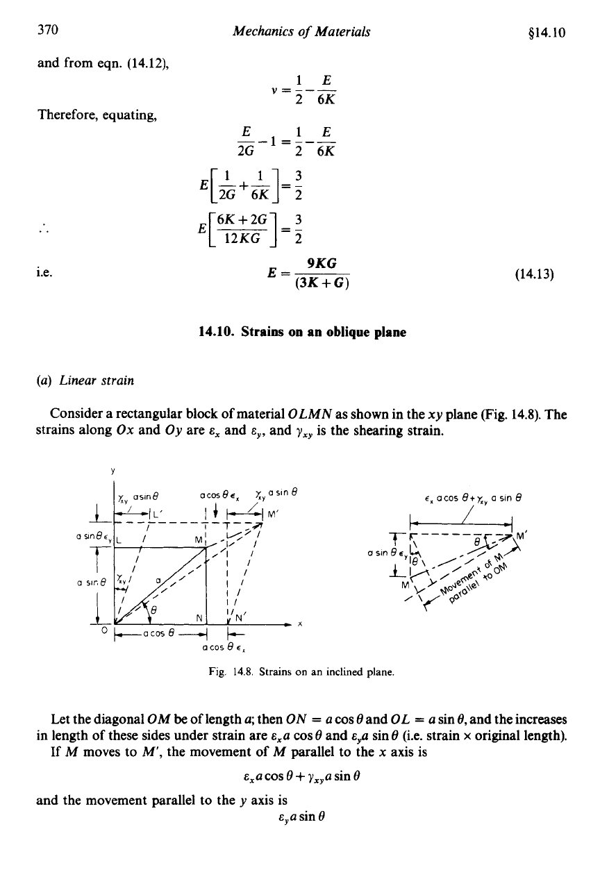
Consider a cube subjected to three equal stresses
6
as in Fig.
14.7
(Le. volumetric
stress
=
6).
Fig.
14.7.
Cubical element subjected to uniform
stress
u
on
all
faces
(“volumetric”
or
“hydrostatic”
stress).
606
Total strain along one edge
=
-
-
v-
-
v-
EEE
6
=
-(1 -2v)
E
But
volumetric strain
=
3
x
linear strain
(see eqn.
14.5)
30
E
=
-(I -2v)
By definition:
volumetric stress
volumetric strain
bulk modulus
K
=
Equating
(3)
and
(4),
..
0
volumetric strain
=
-
K
0
30
KE
-
=
-(1-2v)
(3)
(4)
(14.1 2)
(c)
G,
K
and
v
Equations
(14.1 1)
and
(14.12)
can now be combined to give the final relationship as follows:
From eqn.
(14.1
l),
E
370
and from eqn. (14.12),
Mechanics
of
Materials
Therefore, equating,
..
i.e.
9KG
(3K
+
G)
E=
414.10
(14.13)
14.10.
Strains
on
an
oblique plane
(a) Linear strain
Consider a rectangular block
of
material
OLMN
as shown in the
xy
plane (Fig. 14.8). The
strains along
Ox
and
Oy
are
E,
and
cy,
and
yxy
is the shearing strain.
C,
a
cos
8+
xv
a sin
8
/
Q
+.-acosR-+
+
a
cos
8
E,
Fig.
14.8.
Strains
on
an inclined plane.
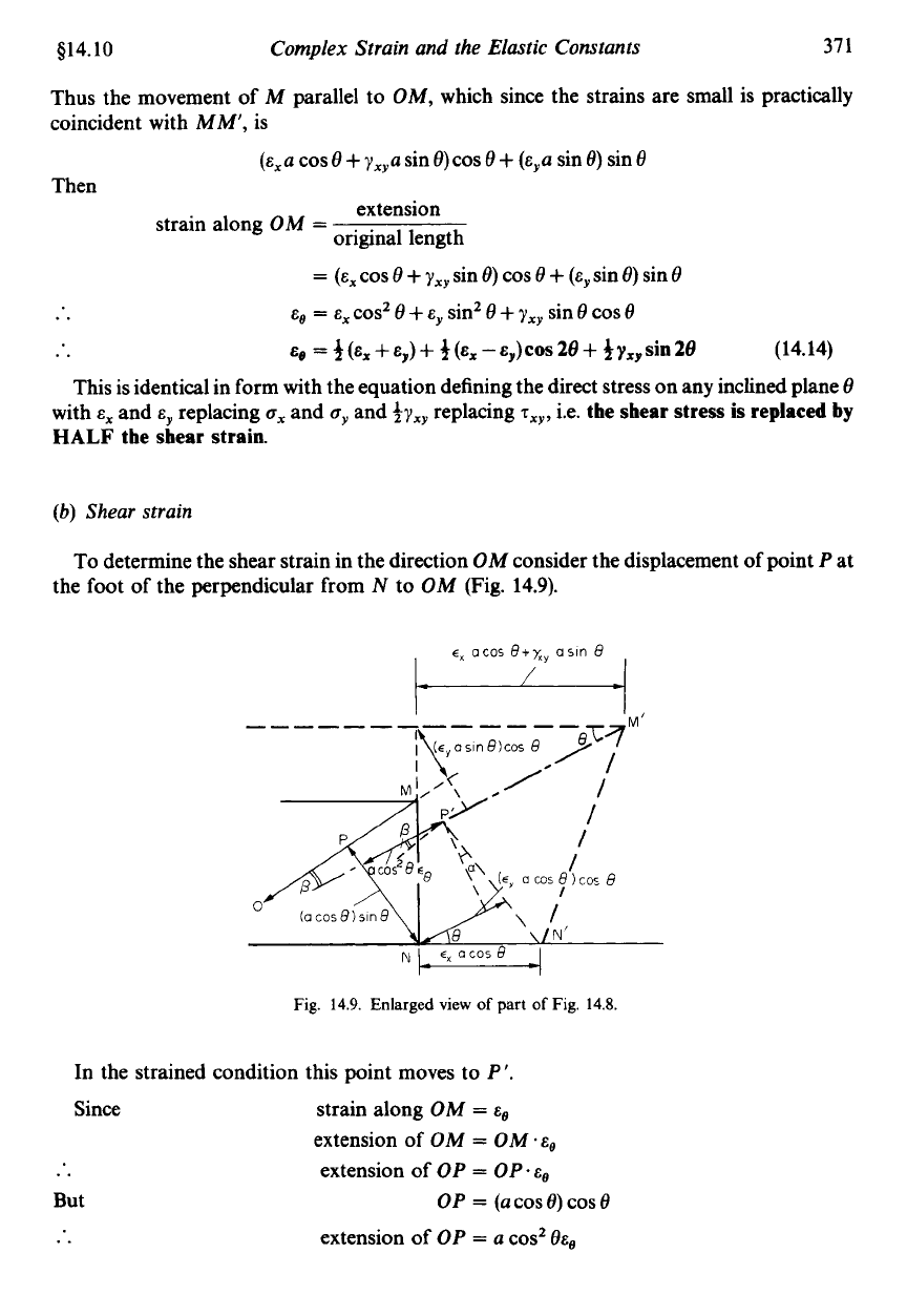
Let the diagonal
OM
be
of
length
a;
then
ON
=
a
cos
8
and
OL
=
a
sin
8,
and the increases
in length
of
these sides under strain are
&,a
cos
8
and
E~U
sin
8
(i.e. strain
x
original length).
If
M
moves to
M',
the movement
of
M
parallel to the
x
axis is
&,a
cos
8
+
?,,a
sin
8
Eya
sin
8
and the movement parallel to the
y
axis is
$14.10
Complex Strain and the Elastic Constants
37
1
Thus the movement of
M
parallel to
OM,
which since the strains are small is practically
coincident with
MM',
is
(&,a
cos
8
+
y,,a
sin 0)cos
8
+
(&,a
sin
6)
sin 8
Then
extension
original length
strain along
OM
=
=
(E,
cos 0
+
yxy
sin
e)
cos
8
+
(ey
sin
e)
sin 8
..
E,
=
E,
cosz
e
+
E,
sinZ
e
+
yxy
sin
e
cos
e
..
Eo
=
3
(E,
+
E,,)
+
3
(E,
-
E,,)
cos
28
+
3
yxp
sin
28
(14.14)
This is identical in form with the equation defining the direct stress on any inclined plane
8
with
E,
and
cy
replacing
ox
and
oy
and
&J,,
replacing
T,~,
i.e.
the shear stress
is
replaced
by
HALF
the shear strain.
(b)
Shear strain
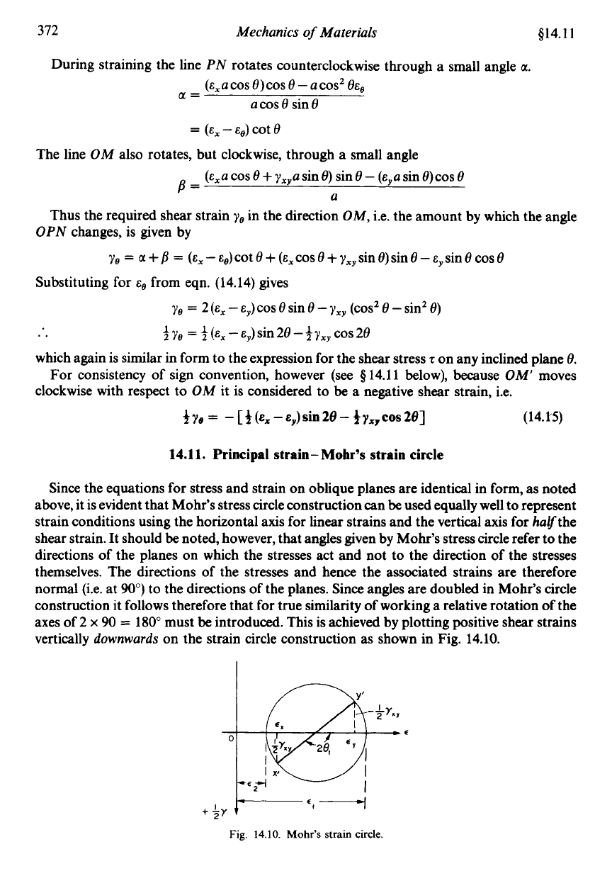
To
determine the shear strain in the direction
OM
consider the displacement
of
point
P
at
the foot
of
the perpendicular from
N
to
OM
(Fig. 14.9).
cX
acos
B+X,
asin
9
w
Fig.
14.9.
Enlarged view
of
part
of
Fig.
14.8.
In the strained condition this point moves to
P'
Since
But
..
strain along
OM
=
E,
extension of
OM
=
OM
extension of
OP
=
OP~E,
extension of
OP
=
a
cosz
eEo
OP
=
(a
COS
e)
COS
e
372
Mechanics
of
Materials
614.1
1
During straining the line
PN
rotates counterclockwise through a small angle
u.
(&,a
cos
e)
cos
e
-
a
cos2
8Ee
a
cos
8
sin
8
U=
=
(E,
-Ee)
cot
8
The line OM also rotates, but clockwise, through a small angle
(&,a
cos
8
+
yxya
sin
8)
sin
8
-
(&,a
sin
8)
cos
8
a
B=
Thus the required shear strain
Ye
in the direction
OM,
i.e. the amount by which the angle
OPN
changes, is given by
ye
=
u
+
B
=
(E,
-
Ee)cot
8
+
(E,COS
8
+
y,,sin 8)sin
8
-
&,sin
8
cos
8
Ye
=
2
(E,
-
E,)
cos
e
sin
8
-
yxy
(cos2
e
-
sin2
e)
Substituting for from eqn. (14.14) gives
..
which again is similar in form to the expression for the shear stress
‘t
on any inclined plane
e.
For consistency
of
sign convention, however
(see
6
14.1 1 below), because
OM’
moves
clockwise with respect to
OM
it is considered to
be
a
negative shear strain, Le.
370
=
3
(E,
-
E,)
sin
28
-$y,,
cos
28
+ye
=
-[3(~,-&~)~i02e-+y~,~0~28]
(14.H)
14.11.
Principal strain-
Mohr’s
strain circle
Since the equations for stress and strain on oblique planes are identical in form, as noted
above, it is evident that Mohr’s stress circle construction can
be
used equally well to represent
strain conditions using the horizontal axis for linear strains and the vertical axis for halfthe
shear strain. It should
be
noted, however, that angles given by Mohr’s stress circle refer to the
directions of the planes on which the stresses act and not to the direction of the stresses
themselves. The directions of the stresses and hence the associated strains
are
therefore
normal @e. at
90”)
to the directions of the planes. Since angles are doubled in Mohr’s circle
construction it follows therefore that for true similarity of working a relative rotation of the
axes
of
2
x
90
=
180” must
be
introduced. This is achieved by plotting positive shear strains
vertically
downwards
on the strain circle construction as shown in Fig. 14.10.
0
+
+Y
Fig.
14.10.
Mohr’s
strain
circle.
