Hearn E.J. Mechanics of Materials. Volume 1
Подождите немного. Документ загружается.

Complex Strain and
the
Elastic Constants
393
(a)
the magnitude of the shear strain;
(b) the other principal strain;
(c) the direction of the principal strain axes;
(d) the magnitudes of the principal stresses if
E
=
200 GN/m' and
v
=
0.3.
Solution
3Y
Fig.
14.32
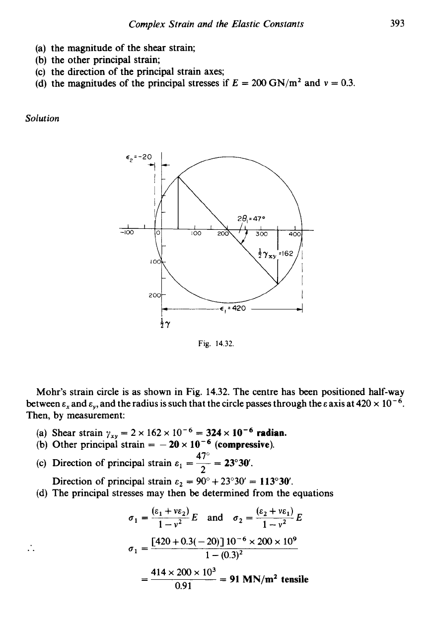
Mohr's strain circle is as shown in Fig. 14.32. The centre has been positioned half-way
between
E,
and
E,,
and the radius is such that the circle passes through the
E
axis at 420
x
Then, by measurement:
Shear strain
yxy
=
2
x
162
x
Other principal strain
=
-
20
x
Direction
of
principal strain
Direction
of
principal strain
E'
=
90"
+
23'30
=
113"30.
The principal stresses may then be determined from the equations
=
324
x
47"
2
radian.
(compressive).
=
-
=
23"30.
[420
+
0.3(
-
20)]
x
200
x
lo9
61
=
1
-
(0.3)'
414
x
200
x
103
-
-
=
91
MN/m2
tensile
0.91
Mechanics
of
Materials
394
and
(-
20
+
0.3
x
42O)lO-j
x
200
x
lo9
a'
=
1
-
(0.3)'
io6
x
200
x
103
=
23.3
MN/mZ
tensile
-
-
0.9
1
Thus the principal stresses are 91 MN/m2 and 23.3 MN/m2, both tensile.
Example
14.7
The following strain readings were recorded at the angles stated relative to
a
given
horizontal axis:
E,
=
-2.9
x
E~
=
E,
=
-0.5
x
lo-'
at 140"
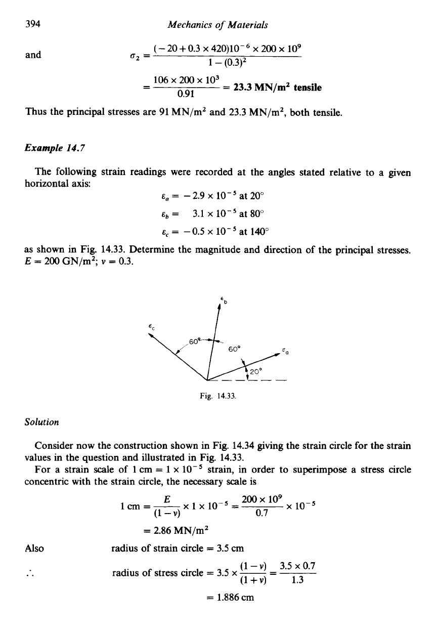
as shown in Fig. 14.33. Determine the magnitude and direction of the principal stresses.
E
=
200 GN/m';
v
=
0.3.
at 20"
3.1
x
lo-'
at 80"
Fig.
14.33.
Solution
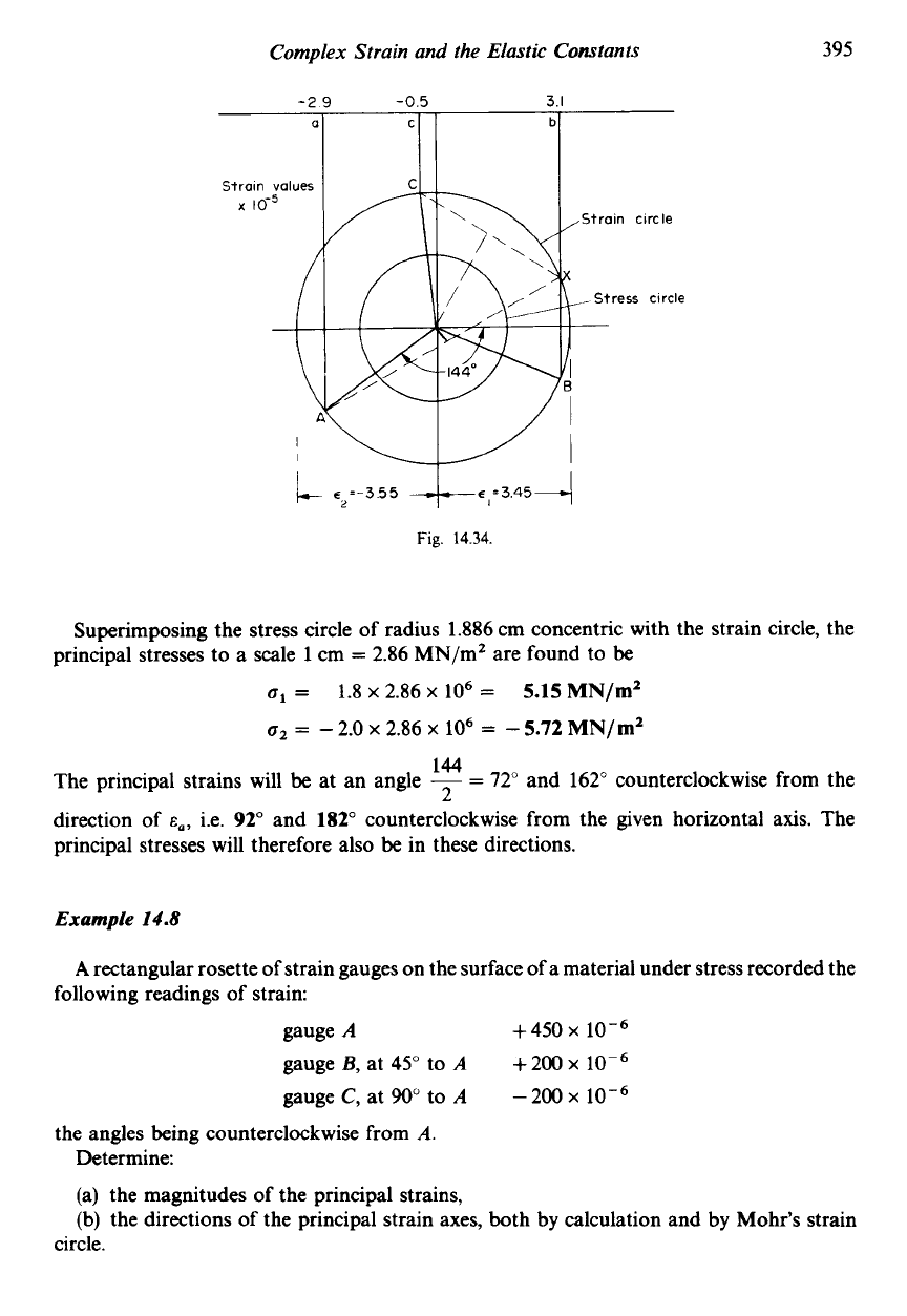
Consider now the construction shown in Fig. 14.34 giving the strain circle for the strain
For a strain scale of 1 cm
=
1
x
lo-'
strain, in order to superimpose a stress circle
values in the question and illustrated in Fig. 14.33.
concentric with the strain circle, the necessary scale is
x
10-5
200
x
109
x
1
x
10-5
=
E
la=-
(1
-
v)
0.7
Also
..
=
2.86 MN/mZ
radius of strain circle
=
3.5 cm
(1
-
V)
3.5
x
0.7
radius of stress circle
=
3.5
x
-
-
(1
+v)
-
1.3
=
1.886cm
Complex Strain and the Elastic Constants
395
it
5=-3.55
+e,=3,454
Fig.
14.34.
Superimposing the stress circle of radius 1.886 cm concentric with the strain circle, the
principal stresses to a scale
1
cm
=
2.86 MN/mZ are found to
be
o1
=
1.8
x
2.86
x
lo6
=
5.15
MN/d
o2
=
-
2.0
x
2.86
x
lo6
=
-
5.72
MN/d
144
The principal strains will
be
at an angle
-
=
72"
and 162" counterclockwise from the
2
direction of
E,,
i.e.
92"
and
182"
counterclockwise from the given horizontal axis. The
principal stresses will therefore also be in these directions.
Example
14.8
A
rectangular rosette of strain gauges
on
the surface
of
a material under stress recorded the
following readings of strain:
gauge
A
+450
x
gauge
B,
at
45"
to
A
+200
x
lop6
gauge
C,
at
90"
to
A
-200
x
the angles being counterclockwise from
A.
Determine:
(a) the magnitudes of the principal strains,
(b)
the directions of the principal strain axes, both
by
calculation and
by
Mohr's strain
circle.
396
Mechanics
of
Materials
Solution
If
E~
and
c2
are the principal strains and
EO
is the strain in a direction at
8
to the direction of
=
+(cl
+
E,)
+
+(e1
-
E~)COS
28
E~,
then eqn. (14.14) may be rewritten as
since
yxy
=
0
on principal strain axes. Thus if gauge
A
is
at an angle
8
to
E~:
450
x
io-6
=
+(E1
+E2)++(E1
-EZ)COS2e
200~
10-6
=+(E1+&2)+3(E1-EZ)COS(900+2e)
-
&,)COS
(180"
+
28)
-
200
x
10-6
=
+(E1
+
E2)
=
+
EZ)
-
E2)COS
28
Adding (1) and (3),
250
x
=
+E,
Substituting (4) in (2),
200
x
10-6
=
125
x
10-6
-EZ)COS
(900
+
28)
..
75
x
=
-&,)sin28
Substituting (4) in (l),
450 x 10-6
=
125
x
i0-6++(~,
-E2)COS2e
..
325 x 10-6
=
-
E2)COS
28
Dividing
(5)
by (6),
75
x
-
-+(E~
-c2)sin28
-
325 x 10-6
-
E2)COS
28
..
tan 28
=
-
0.23
1
..
28
=
-
13"
or 180"
-
13"
=
167"
..
e
=
83030'
Thus gauge
A
is 83'30 counterclockwise from the direction of
cl.
Therefore from (6),
325
x
=
-
E~)COS 167"
=
-667
x
2 x 325
x
..
E1
-E,
=
-
0.9744
(3)
(4)
But from eqn. (4),
Therefore adding,
and subtracting,
el
+E,
=
250
x
2c1
=
-417
x
.*.
=
-
208.5
x
2~~
=
917
x
.'.
EZ
=
458.5
x
Complex Strain and the Elastic Constants
397
Thus the principal strains are
-
208
x
the former being on an axis
83"30'
clockwise from gauge
A.
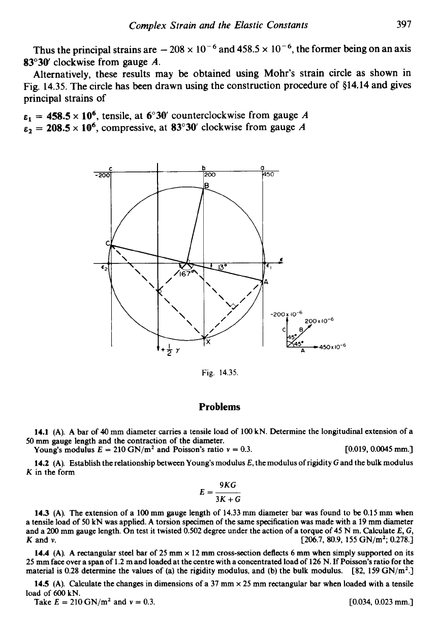
Alternatively, these results may be obtained using Mohr's strain circle as shown in
Fig.
14.35.
The circle has been drawn using the construction procedure of
$14.14
and gives
principal strains of
=
458.5
x
lo6,
tensile, at 6'30 counterclockwise from gauge
A
E~
=
208.5
x
lo6,
compressive, at
8Y30
clockwise from gauge
A
and
458.5
x
Fig.
14.35.
Problems
14.1
(A).
A
bar of
40
mm diameter carries a tensile load of
100
kN. Determine the longitudinal extension of a
Young's
modulus
E
=
210
GN/m2 and Poisson's ratio
v
=
0.3.
c0.019,
0.0045
mm.]
14.2
(A).
Establish the relationship between
Young's
modulus
E,
the modulus of rigidity
G
and the bulk modulus
50
mm gauge length and the contraction
of
the diameter.
K
in
the form
9KG
E=-
3K+G
14.3
(A).
The extension of
a
100
mm gauge length
of
14.33
mm
diameter bar was found to be
0.15
mm when
a tensile load of
50
kN was applied.
A
torsion specimen of the same specification was made with a
19
mm diameter
and a
200
mm gauge length.
On
test it twisted
0.502
degree under the action of a torque of
45
N m. Calculate
E,
G,
K
and
v.
c206.7, 80.9, 155
GN/m2;
0.278.1
14.4
(A).
A
rectangular steel bar of
25
mm
x
12
mm
cross-section deflects
6
mm when simply supported
on
its
25
mm
face
over a
span
of
1.2
m and loaded at the centre with a concentrated load of
126
N. If Poisson's ratio for the
material is
0.28
determine the values of (a) the rigidity modulus, and (b) the bulk modulus.
C82, 159
GN/mZ.]
14.5
(A).
Calculate the changes in dimensions
of
a
37
mm
x
25
mm rectangular bar when loaded with a tensile
load of
600
kN.
Take
E
=
210
GN/mZ and
v
=
0.3.
C0.034, 0.023
mm.]
398
Mechanics
of
Materials
14.6
(A). A
rectangular block of material
125
mm
x
100
mm
x
75
mm carries loads normal to its faces as follows:
1
MN tensile
on
the
125
x
100
mm faces;
0.48
MN tensile on the
100
x
75
mm faces; zero load on the
125
x
75
mm
faces.
If Poisson’s ratio
=
0.3
and
E
=
200
GN/m2, determine the changes in dimensions of the block under load. What
is then the change in volume?
c0.025, 0.0228,
-
0.022
mm;
270
mm’.]
14.7
(A). A
rectangular bar consists of two sections,
AB
25
mm square and
250
mm long and BC
12
mm square
and
250
mm long. For a tensile load
of
20
kN determine:
(a) the change in length
of
the complete bar;
(b) the changes in dimensions
of
each portion.
Take
E
=
80
GN/mz and Poisson’s ratio
v
=
0.3. c0.534
mm;
0.434, -0.003, 0.1, -0.0063
mm.]
14.8
(A). A
cylindrical brass bar is
50
mm diameter and
250
mm long. Find thechange in volume
of
the bar when
an axial compressive load
of
150
kN is applied.
Take
E
=
100
GN/m2 and
v
=
0.27.
[
172.5
mm’.]
14.9
(A).
A
certain alloy bar of
32
mm diameter has a gauge length of
100
mm.
A
tensile load
of
25
kN produces
an extension of
0.014
mm
on
the gauge length and a torque of
2.5
kN m produces an angle of twist of
1.63
degrees.
Calculate
E,
G, K
and
v.
C222, 85.4, 185
GN/m2, 0.3.1
14.10
(A/B).
Derive the relationships which exist between the elastic constants
(a)
E,
G
and
v,
and (b)
E,
K
and
v.
Find the change in volume
of
a steel cube
of
150
mm side immersed to
a
depth of
3
km in
sea
water.
Take
E
for steel
=
210
GN/m2,
v
=
0.3
and the density of
sea
water
=
1025
kg/m’.
[580
mm’.]
14.1 1
(B).
Two steel
bars
have the same length and the same cross-sectional area, one being circular in section and
the other square. Prove that when axial loads are applied the changes in volume of the
bars
are equal.
14.12
(B).
Determine the percentage change in volume of a bar
50
mm square and
1
m long when subjected to an
axial compressive load
of
10
kN. Find also the restraining pressure on the sides of the bar required to prevent all
lateral expansion.
For the bar material,
E
=
210
GN/m2 and
v
=
0.27.
C0.876
x
lo-’
%,
1.48
MN/mZ.]
14.13
(B).
Derive the formula for longitudinal strain due to axial stress ux when all lateral strain is prevented.
A
piece of material
100
mm long by
25
mm square is in compression under a load
of
60
kN. Determine the change
in length of the material if all lateral strain is prevented by the application of a uniform external lateral pressure of
a
suitable intensity.
For the material,
E
=
70
GN/m2 and Poisson’s ratio
v
=
0.25.
c0.114
mm.]
14.14
(B).
Describe briefly an experiment to find Poisson’s ratio for
a
material.
A
steel
bar
of rectangular cross-section
40
mm wide and
25
mm thick is subjected to an axial tensile load of
100
kN. Determine the changes in dimensions of the sides and hence the percentage decrease in cross-sectional area if
E
=
200
GN/rn2 and Poisson’s ratio
=
0.3.
[
-
6
x
lo-’,
-
3.75
x
lo+, -0.03
%.I
14.15
(B).
A
material is subjected to the following strain system:
Determine:
(a) the principal strains;
(b)
the directions of the principal strain axes;
(c) the linear strain on an axis inclined at
50”
counterclockwise to the direction of
E,.
14.16
(B).
A
material is subjected to two mutually perpendicular linear strains together witha shear strain. Given
that this system produces principal strains of
0.0001
compressive and
0.0003
tensile and that one
of
the linear strains
is
0.00025
tensile, determine the magnitudes of the other linear strain and the shear strain.
E,
=
200
x
cy
=
-56
x
y,,
=
230
x
radian
[244,
-
100
x
21”; 163
x
[-
50
x
265
x
14.17
(C).
A
50
mm diameter cylinder is subjected to an axial compressive load
of
80
kN. The cylinder is partially
enclosed by
a
well-fitted casing covering almost the whole length, which reduces the lateral expansion by half.
Determine the ratio between the axial strain when the
casing
is fitted and that when it is free to expand in diameter.
Take
v
=
0.3. c0.871.1
14.18
(C).
A
thin cylindrical shell has hemispherical ends and is subjected to an internal pressure. If the radial
change of the cylindrical part is to be equal to that of the hemispherical ends, determine the ratio between the
thickness necessary in the two parts. Take
v
=
0.3.
C2.43
:
1
.]
14.19
(B).
Determine the values
of
the principal stresses present in the material of Problem
14.16.
Describe an
experimental technique by which the directions and magnitudes
of
these stressescould be determined in practice. For
the material, take
E
=
208
GN/m2 and
v
=
0.3.
C61.6, 2.28
MN/rn2.]
Complex Strain and the Elastic Constants
399
14.20
(B). A rectangular prism of steel is subjected to purely normal stresses
on
all six faoes (i.e. the Stresses
are
principal stresses). One stress is
60
MN/m2 tensile, and the other two are denoted by
u,
and
uy
and
may
be either
tensile or compressive, their magnitudes being such that there is no strain in the direction of
uy
and that the maximum
shearing stress in the material does not exceed
75
MN/m2
on
any plane. Determine the range of values within which
u,
may
lie and the corresponding values of
uy.
Make sketches to show the two limiting states of stress, and calculate
the strain energy
Der
cubic metre of material in the two limiting conditions. Assume that the stresses are not sufficient
to cause elastG-failure. For the prism material
E
=
208
GN/m2;
v
=
0.286.
[U.L.]
[
-
90
to
210;
-
8.6, 77.2
MN/mZ.]
For the following problems on the application
of
strain gauges additional information may be obtained
in
$21.2
(Vol.
2).
14.21
(A/B). The following strains are recorded by two strain gauges, their axes being at right angles:
E,
=
0.00039;
ey
=
-0.00012
(Le. one tensile and one compressive). Find the values of the stresses
ux
and
uy
acting
along these axes if the relevant elastic constants are
E
=
208
GN/m2 and
v
=
0.3. C80.9, -0.69
MN/mZ.]
14.22
(B). Explain how strain gauges
can
be
used
to measure shear strain and hence shear stresses in a material.
Find the value of the shear stress present in a shaft subjected to pure torsion if two strain gauges mounted at
45"
to
the axis of the shaft record the following values
of
strain:
0.00029;
-
0.00029.
If the shaft is of steel,
75
mm diameter,
G
=
80
GN/m2 and
v
=
0.3,
determine the value of the applied torque.
c46.4
MN/mZ,
3.84
kNm.]
14.23
(B). The following strains were recorded
on
a rectangular strain rosette:
E,
=
450
x
Determine:
(a) the principal strains and the directions of the principal strain axes;
(b) the principal stresses if
E
=
200
GN/mZ and
v
=
0.3.
at
91"
clockwise from
A;
98, 29.5
MN/m2.]
14.24
(B). The values of strain given in Problem
14.23
were recorded
on
a
60"
rosette gauge. What are now the
[484
x
-27
x
104
MN/mZ,
25.7
MN/mZ.]
14.25
(B).
Describe briefly how you would proceed, with the aid of strain gauges, to find the principal stresses
Find, by calculation, the principal stresses present in
a
material subjected to a complex stress system given that
and
+
40
x
For the material take
E
=
210
GN/mZ and
v
=
0.3.
[59, 25
MN/m'.]
14.26
(B).
Check the calculation of Problem
14.25
by means
of
Mohr's strain circle.
14.27
(B). Aclosed-ended steel pressure vessel of diameter
2.5
mand plate thickness
18
mm has electric resistance
strain gauges bonded on the outer surface in the circumferential and axial directions. These gauges have a resistance
of
200
ohms and a gauge factor of
2.49.
When the pressure is raised
to
9
MN/mZ the change of resistance is
1.065
ohms for the circumferential gauge and
0.265
ohm for the axial gauge. Working from fust principles calculate
the value
of
Young's
modulus and Poisson's ratio.
[I.Mech.E.]
c0.287, 210
GN/m2.]
14.28
(B). Briefly describe the mode
of
operation of electric resistance strain gauges, and a simple circuit for the
measurement of a static change in strain.
The torque
on
a steel shaft of
50
mm diameter which is subjected to pure torsion is measured by a strain gauge
bonded
on
its outer surface at an angle
of45"
to the longitudinal axis of the shaft. If the change
of
the gauge resistance
is
0.35
ohm in
200
ohms and the strain gauge factor is
2,
determine the torque carried by the shaft. For the shaft
material
E
=
210
GN/mZ and
v
=
0.3.
CI.Mech.E.1
C3.47
kN
.]
14.29
(A/B). A steel test bar
of
diameter
11.3
mm and gauge length
56
mm was found to extend
0.08
mm under
a
load
of
30
kN and to have a contraction
on
the diameter of
0.00452
mm. A shaft of
80
mm diameter, made
of
the
same quality steel, rotates at
420
rev/min. An electrical resistance strain gauge bonded to the outer surface
of
the
shaft at an angle
of
45"
to the longitudinal axis gave a recorded resistance change of
0.189
R.
If
the gauge resistance is
l00R
and the gauge factor is
2.1
determine the maximum power transmitted.
[650
kW.]
14.30
(B).
A
certain equiangular strain gauge rosette is made up of three separate gauges. After it has been
installed it is found that one of the gauges has, in error, been taken from an odd batch; its gauge factor is
2.0,
that of
the other two being
2.2.
As
the
three
gauges appear identical it
is
impossible to
say
which is the rogue and it
is
decided
to proceed with the test. The following strain readings are obtained using a gauge factor setting on the strain gauge
equipment of
2.2:
Gauge direction
0"
60"
120'
E&
=
230
x
E,
=
0.
[451
x
at
1"
clockwise from
A,
-
1
x
values of the principal strains and the principal stresses?
present
on
a material under the action of a complex stress system.
strain readings in directions at
On,
45"
and
90"
to
a
given axis are
+
240
x
respectively.
+
170
x
Strain
x
low6
+1
-250 +200
400
Mechanics
of
Materials
Taking into account the various gauge factor values evaluate the greatest possible shear stress value these readings
can
represent.
[City
U.]
[44
MN/m2.]
For the specimen material
E
=
207
GN/m2 and
v
=
0.3.
14.31
(B).
A solid cylindrical shaft is
250
mm long and
50
mm diameter and is made of aluminium alloy. The
periphery
of
the shaft is constrained in such
a
way as to prevent lateral strain. Calculate the axial force that will
compress the shaft by
0.5
mm.
Determine the change in length of the shaft when the lateral constraint is removed but the axial force remains
unaltered.
Calculate the required reduction in axial force for the nonconstrained shaft if the axial strain is not to exceed
0.2
%
Assume the following values
of
material constants,
E
=
70
GN/m2;
v
=
0.3.
[C.E.I.]
[370
kN
0.673
mm;
95.1
kN.]
14.32
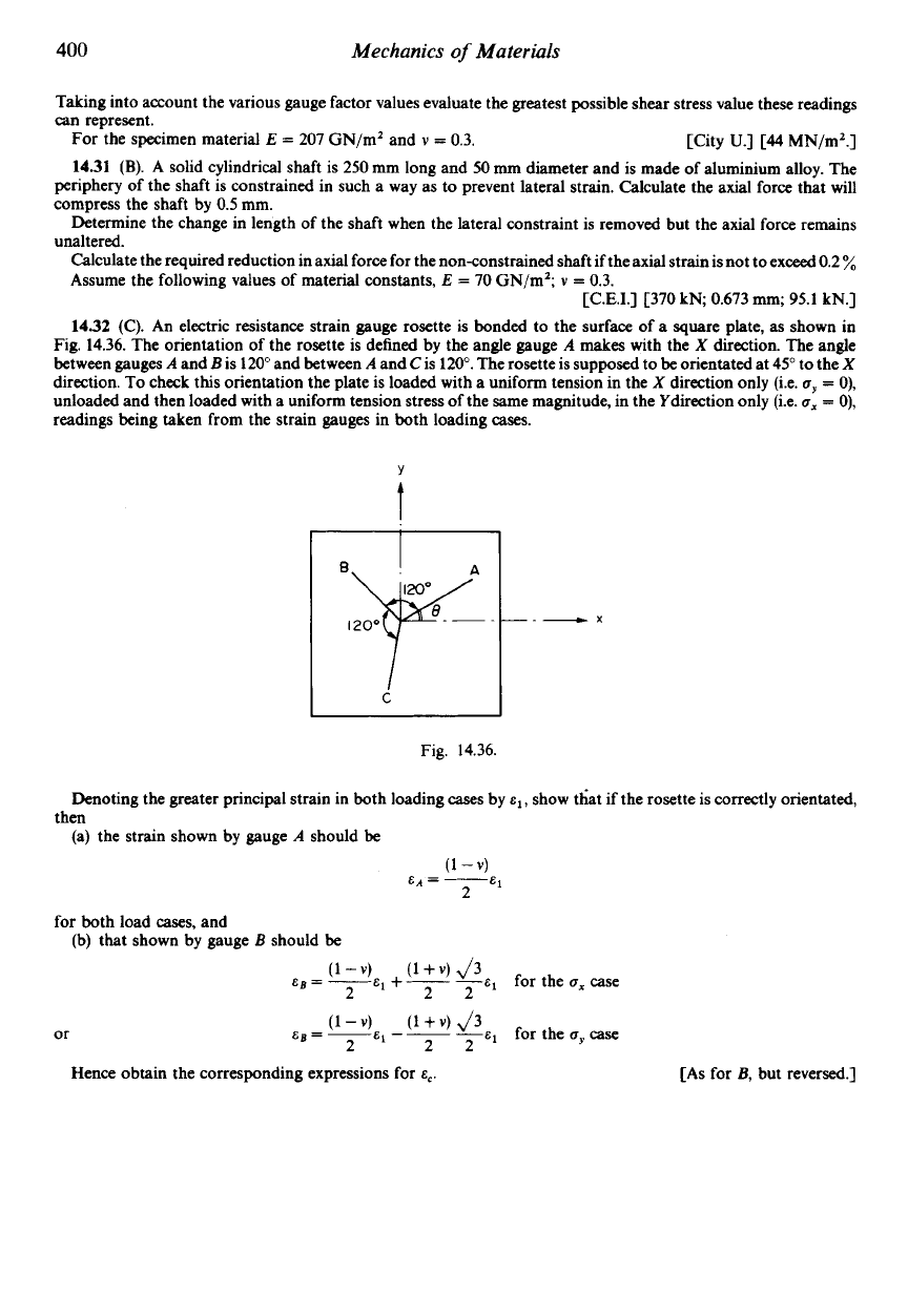
(C). An electric resistance strain gauge rosette is bonded to the surface of
a
square plate, as shown in
Fig.
14.36.
The orientation of the rosette is defined by the angle gauge
A
makes
with the
X
direction. The angle
between gauges
A
and
B
is
120"
and between
A
and
C
is
120".
The rosette is supposed to be orientated at
45"
to the
X
direction. To check this orientation the plate
is
loaded with a uniform tension in the
X
direction only (Le.
uy
=
0),
unloaded and then loaded with a uniform tension stress
of
the same magnitude, in the Ydirection only (i.e.
a,
=
0),
readings being taken from the strain gauges in both loading
cases.
Y
t
B,y:.
C
Fig.
14.36.
_.
-x
Denoting the greater principal strain in both loading
cases
by
el,
show tht if the rosette is correctly orientated,
(a)
the strain shown by gauge
A
should be
then
for both load cases, and
(b) that shown by gauge
B
should be
Eg
=
__
('
-')
E1
+-
('
-
fq
for the
u,
case
2 2
or
Eg
=
~
('
-
El
--
('
+
-
i3
for the
uy
case
2 2
Hence obtain the corresponding expressions for
E,.
[As for
B,
but reversed.]
CHAPTER
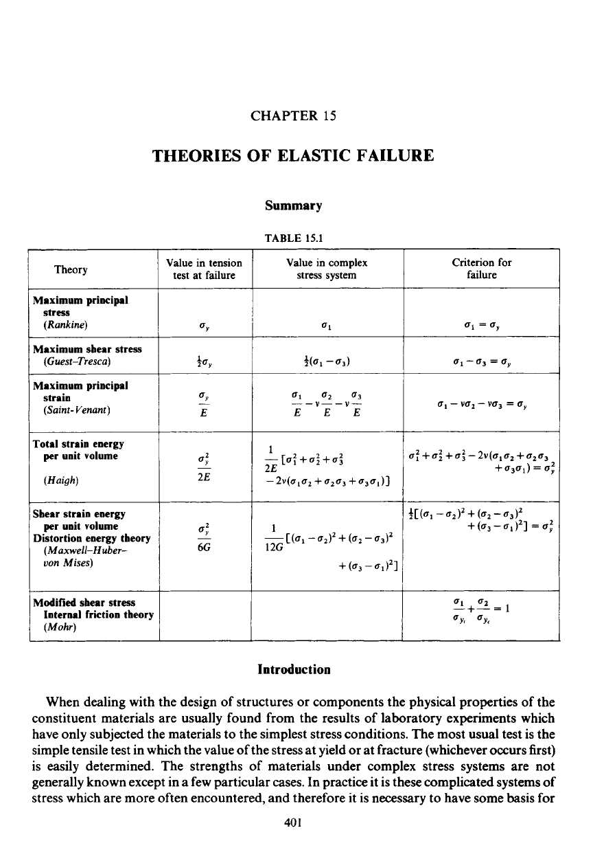
15
THEORIES OF ELASTIC FAILURE
Maximum principal
stress
(Rankine)
(Guest-Tresca)
strain
(Saint- Venant)
Maximum sbear stress
Maximum principal
Total strain energy
per
unit volume
(Haigh)
Summary
TABLE
15.1
UY
+%
UY
E
-
U:
-
2E
Value in tension
1
test at failure
1
Theory
I
I
Sbear strain energy
per unit volume
Distortion energy tbeory
(Maxwell-Huh-
uon Mises)
4
6G
Modified sbear stress
Internal friction theory
Value in complex
stress system
1
2E
-
[Uf
+
u:
+a:
-
2V(UlU2
+
u2u3
+
u3u1)]
1
12G
-[(a1
-
Criterion for
failure
u1
=uy
61
-
03
=
6,
u,
-
vu2
-
vu3
=
cry
u:
+
u:
+
u:
-
2v(u,u2
+
u2u3
+
u3u1)
=
u;
Introduction
When dealing with the design of structures or components the physical properties
of
the
constituent materials are usually found from the results of laboratory experiments which
have only subjected the materials to the simplest stress conditions. The most usual test is the
simple tensile test in which the value of the stress at yield or at fracture (whichever occurs first)
is easily determined. The strengths of materials under complex stress systems are not
generally known except in a few particular cases. In practice it is these complicated systems
of
stress which are more often encountered, and therefore it is necessary to have some basis for
40
1
402
Mechanics
of
Materials
$15.1
determining allowable working stresses
so
that failure will not occur. Thus the function of the
theories of elastic failure is to predict from the behaviour of materials in
a
simple tensile test
when elastic failure will occur under
any
condition of applied stress.
A
number of theoretical criteria have been proposed each seeking to obtain adequate
correlation between estimated component life and that actually achieved under service load
conditions for both brittle and ductile material applications. The five main theories are:
(a) Maximum principal stress theory (Rankine).
(b) Maximum shear stress theory (Guest-Tresca).
(c) Maximum principal strain (Saint-Venant).
(d) Total strain energy per unit volume (Haigh).
(e) Shear strain energy per unit volume (Maxwell-Huber-von Mises).
In each case the value of the selected critical property implied in the title of the theory is
determined for both the simple tension test and
a
three-dimensional complex stress system.
These values are then equated to produce the so-called
criterion for failure
listed in the last
column of Table
15.1.
In Table
15.1
u,,
is the stress at the yield point in the simple tension test, and
ul,
u2
and
u3
are the three principal stresses in the three-dimensional complex stress system in order of
magnitude. Thus in the case of the maximum shear stress theory
u1
-u3
is the greatest
numerical difference between two principal stresses taking into account signs and the fact
that one principal stress may be zero.
Each of the first five theories listed in Table
15.1
will be introduced in detail in the following
text, as will a sixth theory, (f)
Mobr's modified sbear stress theory.
Whereas the previous
theories (a) to (e) assume equal material strength in tension and compression, the Mohr's
modified theory attempts to take into account the additional strength of brittle materials in
compression.
15.1.
Maximum principal stress theory
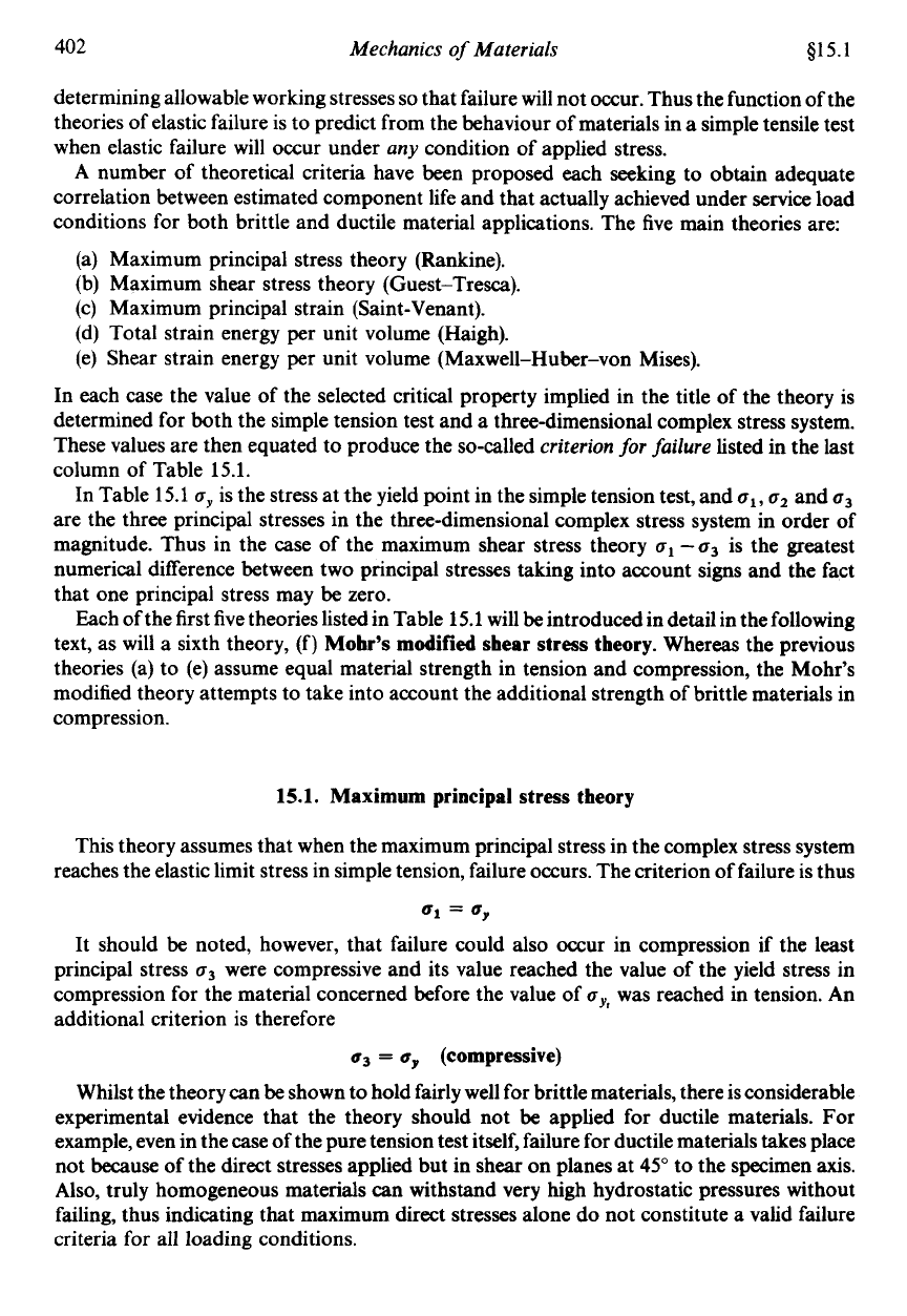
This theory assumes that when the maximum principal stress in the complex stress system
reaches the elastic limit stress in simple tension, failure occurs. The criterion of failure is thus
Ul
=
by
It
should be noted, however, that failure could also occur in compression if the least
principal stress
u3
were compressive and its value reached the value
of
the yield stress in
compression for the material concerned before the value of
u,,,
was reached in tension. An
additional criterion is therefore
uj
=
up
(compressive)
Whilst the theory can be shown to hold fairly well for brittle materials, there is considerable
experimental evidence that the theory should not
be
applied for ductile materials. For
example, even in the case of the pure tension test itself, failure for ductile materials takes place
not because of the direct stresses applied but in shear on planes at
45"
to the specimen
axis.
Also, truly homogeneous materials can withstand very high hydrostatic pressures without
failing, thus indicating that maximum direct stresses alone do not constitute a valid failure
criteria for all loading conditions.
