Hearn E.J. Mechanics of Materials. Volume 1
Подождите немного. Документ загружается.

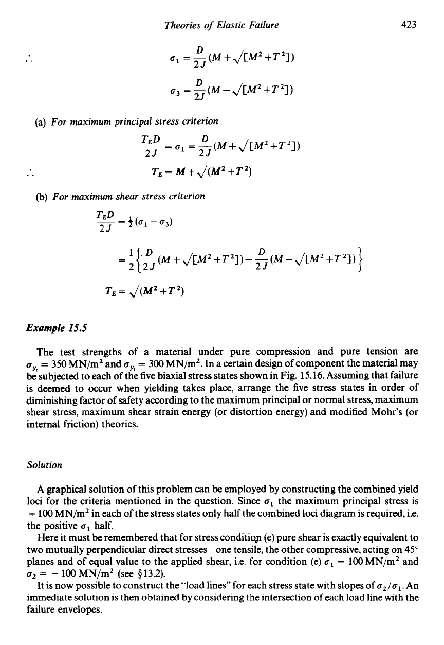
Theories
of
Elastic Failure
423
..
D
25
D
25
o1
=-(M+J[MZ+Tz])
a3
=-(M-J[MZ+T2])
(a)
For
maximum principal stress criterion
D
25
25
TED
--
-
01
=
-
(M
+
J[MZ
+Tq)
..
T~
=
M
+
J(M~
+T~)
(b)
For
maximum shear stress criterion
D
25
-
(M
+
J[MZ
+TZ])
-
-
(M
-
J[MZ
+TZ])
Example
15.5
The test strengths of a material under pure compression and pure tension are
UY,
- -
350
MN/mZ and
cy,
=
300
MN/mZ. In a certain design of component the material may
be
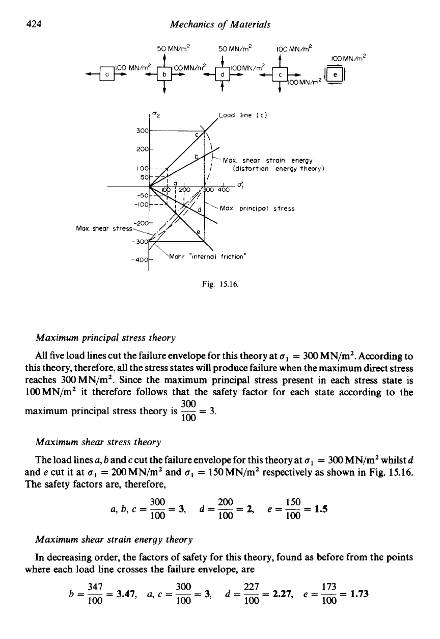
subjected to each of the five biaxial stress states shown in Fig.
15.16.
Assuming that failure
is deemed to occur when yielding takes place, arrange the five stress states in order of
diminishing factor of safety according to the maximum principal or normal stress, maximum
shear stress, maximum shear strain energy (or distortion energy) and modified Mohr’s (or
internal friction) theories.
Solution
A
graphical solution of this problem can
be
employed by constructing the combined yield
loci for the criteria mentioned in the question. Since
u1
the maximum principal stress is
+
100
MN/mZ in each of the stress states only half the combined loci diagram is required, i.e.
the positive
u1
half.
Here it must
be
remembered that for stress conditio8 (e) pure shear is exactly equivalent to
two mutually perpendicular direct stresses
-
one tensile, the other compressive, acting on
45”
planes and of equal value to the applied shear, i.e. for condition (e)
a1
=
100
MN/m2 and
az
=
-
100
MN/m2
(see
$13.2).
It is now possible to construct the “load lines” for each stress state with slopes of
az/al.
An
immediate solution is then obtained by considering the intersection of each load line with the
failure envelopes.
424
Mechanics
of
Materials
Max.
Load line
(c)
Max shear strain energy
(distortion energy theory)
Max. principal stress
shear stress
Fig.
15.16.
Maximum principal stress theory
All five load lines cut the failure envelope for this theory at
o1
=
300 MN/mZ. According to
this theory, therefore, all the stress states will produce failure when the maximum direct stress
reaches 300MN/m2. Since the maximum principal stress present in each stress state is
100MN/mZ it therefore follows that the safety factor for each state according to the
maximum principal stress theory is
-
=
3.
300
100
Maximum shear stress theory
The load lines
a,
band
c
cut the failure envelope for this theory at
o1
=
300 MN/m2 whilst
d
and
e
cut it at
o1
=
200 MN/m2 and
o1
=
150 MN/m2 respectively as shown in Fig. 15.16.
The safety factors are, therefore,
300 200 150
100
a,b,c=---=3,
d=-=2
e=--.=15
100
'
100
*
Maximum shear strain energy theory
In decreasing order, the factors of safety for this theory, found
as
before from the points
where each load line crosses the failure envelope, are
Theories
of
Elastic Failure
425
Mohr’s modified or internal friction theory (with
cy,
=
350
MN/mZ)
In this case the safety factors are:
Example
15.6
The cast iron used in the manufacture of an engineering component has tensile and
(a) If the maximum value of the tensile principal stress is to
be limited to one-quarter of the
tensile strength, determine the maximum value and nature of the other principal stress
using Mohr’s modified yield theory for brittle materials.
(b) What would
be
the values
of
the principal stresses associated with a maximum shear
stress of
450
MN/mZ according to Mohr’s modified theory?
(c) At some point in a component principal stresses of 100MN/mZ tensile and
100MN/mZ compressive are found to
be
present. Estimate the safety factor with
respect to initial yield using the maximum principal stress, maximum shear stress,
distortion energy and Mohr’s modified theories of elastic failure.
compressive strengths of
400
MN/m2 and 1.20 GN/mZ respectively.
k2=-7WMN/mZ
~l!iCl
MN/m2
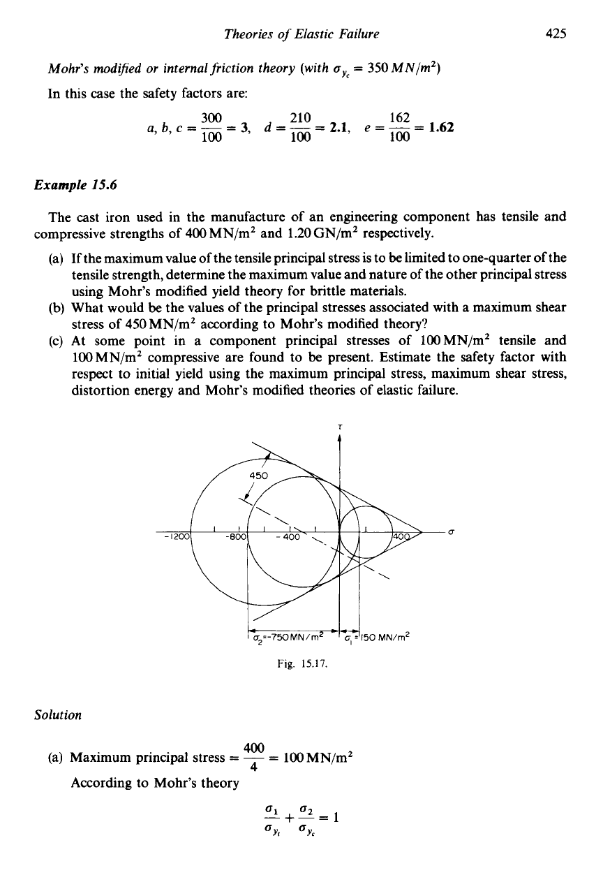
Fig.
15.17.
Solution
400
4
(a)
Maximum principal stress
=
-
=
100MN/mZ
According to Mohr’s theory
426
Mechanics
of
Materials
100
x
lo6
02
400
x
io6
+
-
1.2
x
109
.,
..
o2
=
-
1.2
x
109(1
-
a)
=
-900MN/m2
(b)
In any Mohr circle construction the radius of the circle equals the maximum shear
stress value. In order to answer this part of the question, therefore, it is necessary to
draw the Mohr failure envelope on
o-r
axes as shown in Fig.
15.17
and to construct the
circle which is tangential to the envelope and has a radius of 450MN/m2. This is
achieved
by
drawing a line parallel to the failure envelope and a distance
of
450
MN/m2 (to scale) from it. Where this line cuts the
CJ
axis is then the centre of the
required circle. The desired principal stresses are then, as usual, the extremities of the
horizontal diameter of the circle.
Thus from Fig.
15.17
ul
=
150
MN/m2
and
u2
=
-
750
MN/m2
(c) The solution here
is
similar to that used for Example
15.5.
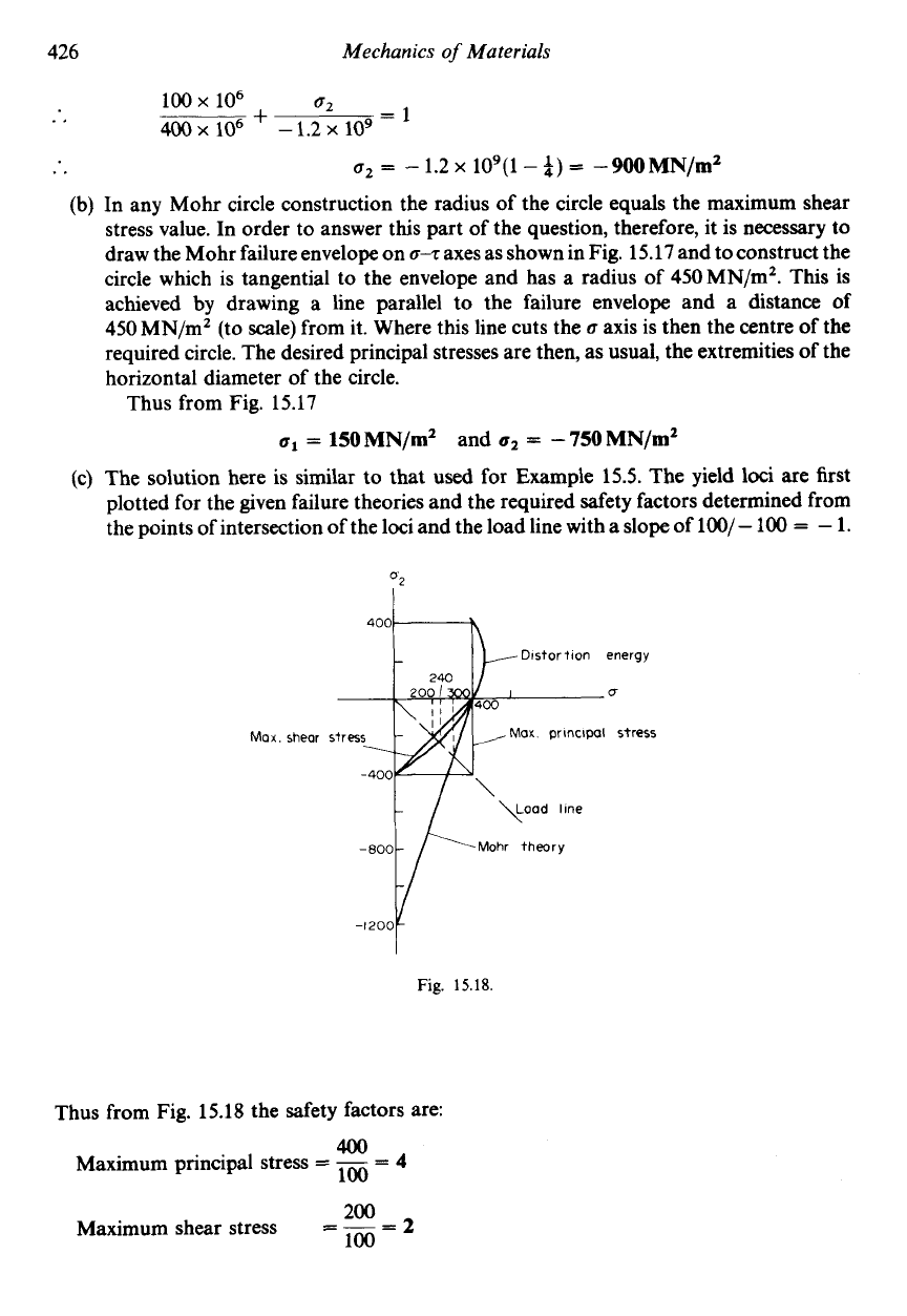
The yield loci are first
plotted for the given failure theories and the required safety factors determined from
the points of intersection
of
the loci and the load line with a slope of
100/
-
100
=
-
1.
400k2
Distortion
energy
Max principal
stress
Fig.
15.18.
Thus from Fig.
15.18
the safety factors are:
Maximum principal stress
=
-
=
4
=
-
=
2
400
100
200
100
Maximum shear stress
Theories
of
Elastic Failure
427
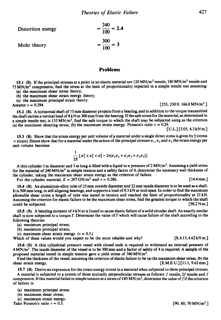
Distortion energy
Mohr theory
240
=
-
=
2.4
100
300
-
--=3
100
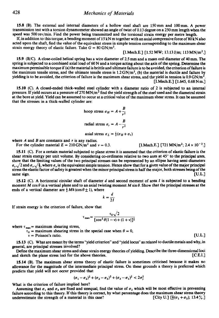
Problems
15.1
(B).
If the principal stresses at a point in an elastic material are
120
MN/m2 tensile,
180
MN/m2 tensile and
75
MN/m2 compressive, find the stress at the limit of proportionality expected in a simple tensile test assuming:
(a) the maximum shear stress theory;
(b) the maximum shear strain energy theory;
(c) the maximum principal strain theory.
Assume
v
=
0.294.
[255, 230.9, 166.8
MN/m2.]
15.2
(B).
A horizontal shaft of
75
mm
diameter projects from a bearing, and in addition to the torque transmitted
the shaft carries a vertical load of
8
kN at
300
mm from the bearing. If the safe stress for the material,
as
determined in
a simde tensile test. is
135
MN/m2. find the safe torque to which the shaft may be subjected using as the criterion
(a) the maximum shearing stress; (b) the maximum strain energy. Poisson’s ratio
v
=
0.29.
[U.L.]
C5.05, 6.3
kNm.]
15.3
(B).
Show that the strain energy per unit volume of a material under a single direct stress is given by
f
(stress
x
strain). Hence show that for a material under the action of the principal stresses
ul,
u2
and
u3
the strain energy per
unit volume becomes
A
thin cylinder
1
m diameter and
3
m long is filled with a liquid to a pressure of
2
MN/m2. Assuming a yield stress
for the material of
240
MN/m2 in simple tension and a safety factor of
4,
determine the necessary wall thickness of
the cylinder, taking the maximum shear strain energy as the criterion of failure.
For the cylinder material,
E
=
207
GN/mz and
v
=
0.286.
[
14.4
mm.]
15.4
(B).
An aluminium-alloy tube of
25
mm
outside diameter and
22
mm inside diameter is to be
used
as
a shaft.
It is
Mo
mm
long, in self-aligning bcarings, and supports a load of
0.5
kN at mid-span. In order to find the maximum
allowable shear stress a length of tube was tested in tension and reached the limit of proportionality at
21
kN.
Assuming the criterion for elastic failure to be the maximum shear stress, find the greatest torque to which the shaft
could be subjected.
C98.2
N
m.]
15.5
(B).
A
bending moment of
4
kN m is found to
cause
elastic failure of a solid circular shaft. An exactly similar
shaft is now subjected to a torque
T.
Determine the value of
T
which will
cause
failure of the shaft according to the
following theories:
(a) maximum principal stress;
(b) maximum principal strain;
(c) maximum shear strain energy.
(v
=
0.3.)
Which of these values would you expect to be the most reliable and why?
[8,6.15,4.62
kNm.]
15.6
(B).
A
thin cylindrical pressure vessel with closed ends is required to withstand an internal pressure of
4
MN/m2. The inside diameter of the vessel is to be
Momm
and
a
factor of safety of
4
is required.
A
sample of the
proposed material tested in simple tension gave a yield stress
of
360
MN/mz.
Find the thickness of the vessel, assuming the criterion of elastic failure to be (a) the maximum shear stress, (b) the
shear strain energy. [E.M.E.U.]
[11.1,9.62mm.l
15.7
(B).
Derive an expression for the strain energy stored in
a
material when subjected to three principal stresses.
A
material is subjected to a system of three mutually perpendicular stresses
as
follows:
f
tensile,
2f
tensile and
f
compressive. If this material failed in simple tension at a stress of
180
MN/m2, determine the value offif the criterion
of failure is:
(a) maximum principal stress;
(b) maximum shear stress;
(c) maximum strain energy.
Take Poisson’s ratio
v
=
0.3.
1
2E
-
cu:
+
u:
+
u:
-
2v(u,u2
+
u1u3
+
u2u3)]
[W,
60,70
MN/m2.]
428
Mechanics
of
Materials
15.8
(B). The external and internal diameters of a hollow steel
shaft
are l5Omm and 100mm.
A
power
transmission test with a torsion dynamometer showed an angle of twist of 0.13 degree
on
a 250
mm
length when the
speed
was 500 rev/min. Find the power being transmitted and the torsional strain energy per metre length.
If, in addition to this torque, a bending moment of 15 kN m together with an axial compressive force of
80
kN also
acted upon the shaft, find the value of the equivalent stress in simple tension corresponding
to
the maximum shear
strain energy theory of elastic failure. Take
G
=
80
GN/m2.
CI.Mech.E.1 C1.52 MW; 13.13 J/m; 113 MN/m2.]
15.9
(B/C).
A
closecoiled helical spring has a wire diameter of 2.5
mm
and a mean
coil
diameter of 4Omm. The
spring is subjected
to
a combined axial load of 60N and a torque acting about the
axis
of the spring. ktermine the
maximum permissible torque if (a) the material is brittle and ultimate failure is to beavoided, the criterion
of
failure is
the maximum tensile stress, and the ultimate tensile stress is 1.2 GN/m2, (b) the material is ductile and failure by
yielding is
to
be avoided, the criterion of failure is the maximum shear stress, and the yield in tension is
0.9
GN/m2.
CI.Mech.E.1 [1.645,0.68Nm.l
15.10
(C).
A
closed-ended thick-walled
steel
cylinder with
a
diameter ratio
of
2 is subjected
to
an internal
pressure. If yield
occurs
at a pressure of
270
MN/m2 find the yield strength of the steel
used
and the diametral strain
at the bore at yield. Yield can
be
assumed to occur at a critical value of the maximum shear stress.
It
can be assumed
that the stresses in a thick-walled cylinder are:
B
hoop stress UH
=
A
+
-
r2
B
radial stress
a,
=
A
-
-
rz
axial stress
uL
=
+(an+
ur)
where
A
and
B
are constants and
r
is any radius.
For the cylinder material
E
=
210GN/m2 and
v
=
0.3.
15.11
(C). For a certain material subjected to plane stress it is assumed that the criterion of elastic failure is the
shear strain energy per unit volume. By considering cosrdinates relative
to
two axes at 45”
to
the principal axes,
show that the limiting values of the two principal stresses
can
be represented by an ellipse having semi-diameters
u,J2
and
ae,/f,
where
a,
is the equivalent simple tension. Hence show that for a given value of the major principal
stress the elastic factor of safety is greatest when the minor principal stress is
half
the major, both stresses being of the
15.12
(C).
A
horizontal circular shaft of diameter
d
and second moment of area
I
is subjected to
a
bending
moment
M
cos
0
in a vertical plane and to an axial twisting moment
M
sin
0.
Show
that
the principal stresses at the
ends of
a
vertical diameter are
+
Mk
(cos
0
f
l), where
d
k=-
21
[I.Mech.E.] [721 MN/m2; 2.4
x
same sign. [U.L.]
If strain energy is the criterion of failure, show that
20
J2
[cos2
e(i
-
V)
+
(1
+
v)]t
tmx=
where
T-=
maximum shearing stress,
to
=
maximum shearing stress in the special
case
when
0
=
0,
v
=
Poisson’s ratio. [U.L.]
15.13
(C). What are meant by the terms “yield criterion” and “yield
locus”
as related to ductile metals and why, in
general, are principal stresses involved?
Deline the maximum shear stress and shear strain energy theories of yielding. Describe the three-dimensional
loci
and sketch the plane stress
loci
for the above theories.
[C.E.I.]
15.14
(B).
The maximum shear stress theory of elastic failure is sometimes criticised because it makes no
allowance for the magnitude of the intermediate principal stress.
On
these grounds a theory is preferred which
predicts that yield will not occur provided that
(a1
-
u2)2
+
(u2
-
u3)2
+
(a3
-
u1)2
<
24
What is the criterion
of
failure implied here?
Assuming that
U,
and
a3
are fixed and
unequal,
lind the value of
u2
which will
be
most effective in preventing
failure according
to
this theory. If this theory is correct, by what percentage does the maximum shear
stress
theory
underestimate the strength of a material in
this
case?
[City U.]
[+(a,
+a,);
13.4z.1
Theories
of
Elastic Failure
429
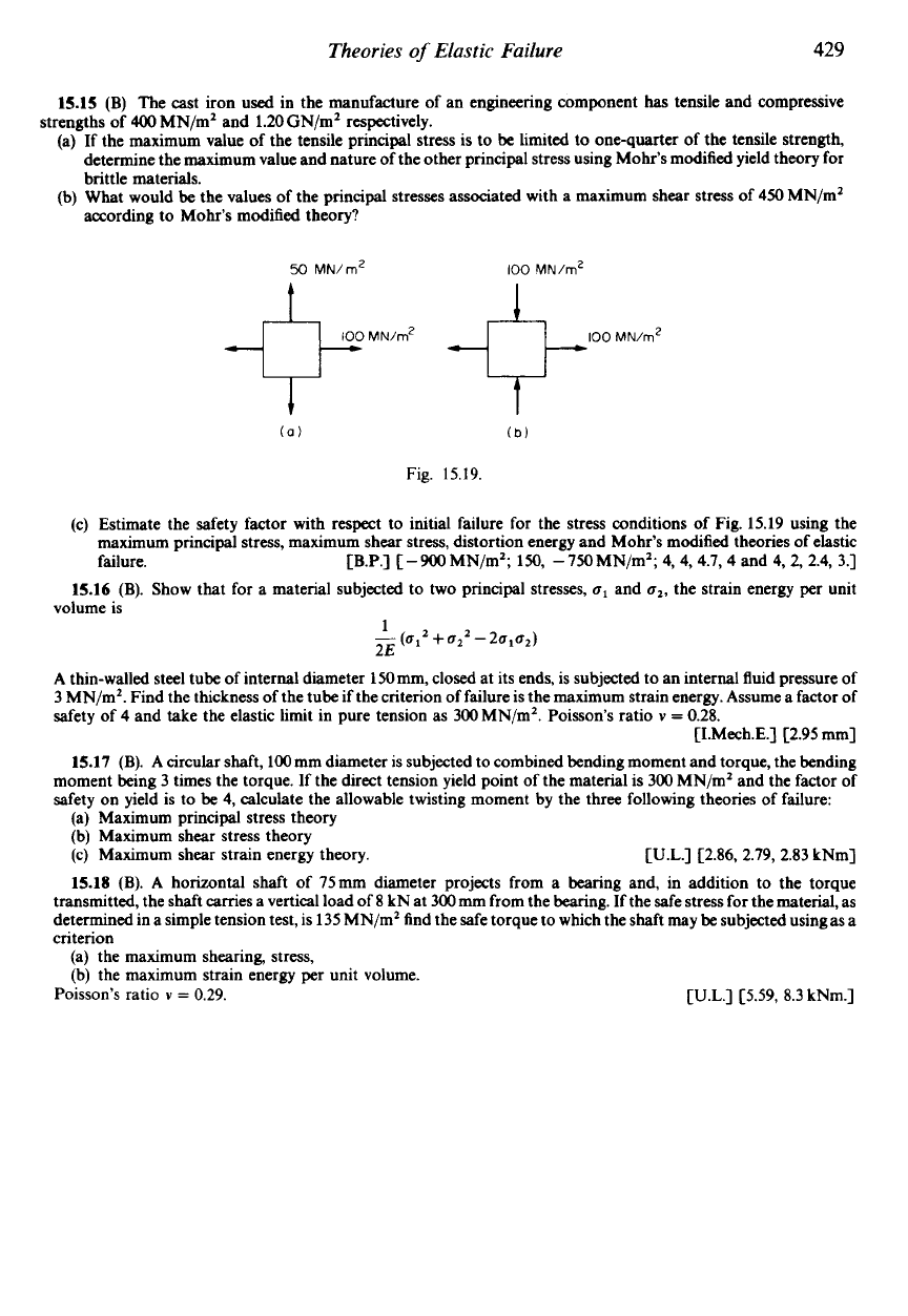
15.15
(B)
The wt iron
used
in the manufacture of an engineering component
has
tensile and compressive
(a) If the maximum value of the tensile principal stress is to be limited to one-quarter of the tensile strength,
determine the maximum value and nature of the other principal stress using Mohr’s modified yield theory for
brittle materials.
(b) What would be the values of the principal stresses associated with a maximum shear stress of
450
MN/mZ
according to Mohr’s modified theory?
strengths of
400
MN/m2 and 1.20GN/mZ respectively.
50
MN/rn2
100
MN/rn2
MN/rnz
Fig. 15.19.
(c) Estimate the safety factor with respect to initial failure for the stress conditions of Fig.
15.19
using the
maximum principal stress, maximum shear stress, distortion energy and Mohr’s modified theories of elastic
failure.
[B.P.]
[-900MN/m2; 150, -750MN/m2; 4,4, 4.7,
4
and 4, 2, 2.4, 3.1
15.16
(B).
Show that for
a
material subjected to two principal stresses,
u1
and
u2,
the strain energy per unit
volume is
1
-
2E
(a12
+
u22
-
2u1u2)
A
thin-walled steel tube of internal diameter 150mm, closed at its ends, is subjected to an internal fluid pressure of
3
MN/m2. Find the thickness of the tube if the criterion
of
failure is the maximum strain energy. Assume
a
factor
of
safety of
4
and take the elastic limit in pure tension as 300 MN/m2. Poisson’s ratio
v
=
0.28.
CI.Mech.E.1 C2.95 mm]
15.17
(B).
A
circular shaft,
100
mm diameter is subjected to combined bending moment and torque, the bending
moment being 3 times the torque. If the direct tension yield point of the material is 300 MN/m2 and the factor of
safety on yield is to be 4, calculate the allowable twisting moment by the three following theories of failure:
(a) Maximum principal stress theory
(b) Maximum shear stress theory
(c)
Maximum shear strain energy theory.
[U.L.] c2.86, 2.79, 2.83 kNm]
15.18
(B).
A
horizontal shaft of 75mm diameter projects from a bearing and, in addition to the torque
transmitted, the shaft
carries
a vertical load
of
8
kN at
300
mm
from the bearing. If the safe stress for the material, as
determined in a simple tension test, is 135 MN/mZ find the safe torque to which the shaft
may
be subjected usingas
a
criterion
(a) the maximum shearing, stress,
(b) the maximum strain energy per unit volume.
Poisson’s ratio
v
=
0.29.
[U.L.]
C5.59,
8.3 kNm.]
CHAPTER
16
EXPERIMENTAL STRESS ANALYSIS
Introduction
We live today in
a
complex world of manmade structures and machines. We work in
buildings which may be many storeys high and travel in cars and ships, trains and planes; we
build huge bridges and concrete dams and send mammoth rockets into space. Such is our
confidence in the modern engineer that we take these manmade structures for granted. We
assume that the bridge will not collapse under the weight of the car and that the wings will not
fall away from the aircraft. We are confident that the engineer has assessed the stresses within
these structures and has built in sufficient strength to meet all eventualities.
This attitude of mind is a tribute to the competence and reliability of the modern engineer.
However, the commonly held belief that the engineer has been able to calculate mathemati-
cally
the stresses within the complex structures is generally ill-founded. When he is dealing
with familiar design problems and following conventional practice, the engineer draws on
past experience in assessing the strength that must be built into a structure.
A
competent civil
engineer, for example, has little difficulty in selecting the size of steel girder that he needs to
support a wall. When he departs from conventional practice, however, and is called upon to
design unfamiliar structures or to use new materials or techniques, the engineer can no longer
depend upon past experience. The mathematical analysis of the stresses in complex
components may not, in some cases, be a practical proposition owing to the high cost of
computer time involved. If the engineer has no other way of assessing stresses except by
recourse to the nearest standard shape and hence analytical solution available, he builds in
greater strength than he judges to be necessary (i.e. he incorporates
a
factor of safety) in the
hope of ensuring that the component will not fail in practice. Inevitably, this means
unnecessary weight, size and cost, not only in the component itself but also in the other
members of the structure which are associated with it.
To
overcome this situation the modern engineer makes use of experimental techniques of
stress measurement and analysis. Some of these consist of “reassurance” testing of completed
structures which have been designed and built on the basis of existing analytical knowledge
and past experience: others make use of scale models to predict the stresses, often before final
designs have been completed.
Over the past few years these
experimental stress analysis
or
strain measurement
techniques
have served an increasingly important role in aiding designers to produce not only efficient
but economic designs. In some cases substantial reductions in weight and easier manufactur-
ing processes have been achieved.
A
large number of problems where experimental stress analysis techniques have been of
particular value are those involving fatigue loading. Under such conditions failure usually
starts when a fatigue crack develops at some position of high localised stress and propagates
430
$16.1
Experimental Stress Analysis
43
1
until final rupture occurs.
As
this often requires several thousand repeated cycles of load
under service conditions, full-scale production is normally well under way when failure
occurs. Delays at this stage can
be
very expensive, and the time saved
by
stress analysis
techniques in locating the source of the trouble can far outweigh the initial cost
of
the
equipment involved.
The main techniques of experimental stress analysis which are in use today are:
(1)
brittle lacquers
(2)
strain gauges
(3)
photoelasticity
(4)
photoelastic coatings
The aim of this chapter is to introduce the fundamental principles of these techniques,
together with limited details of the principles of application, in order that the reader can
appreciate (a) the role
of
the experimental techniques as against the theoretical procedures
described in the other chapters,
(b)
the relative merits of each technique, and (c) the more
specialised literature which is available on the techniques, to which reference will
be
made.
16.1.
Brittle lacquers
The brittle-lacquer technique of experimental stress analysis relies on the failure by crack-
ing of a layer of a brittle coating which has been applied to the surface under investigation.
The coating is normally sprayed onto the surface and allowed to air- or heat-cure to attain its
brittle properties. When the component is loaded, this coating will crack as its so-called
threshold strain
or
strain sensitivity
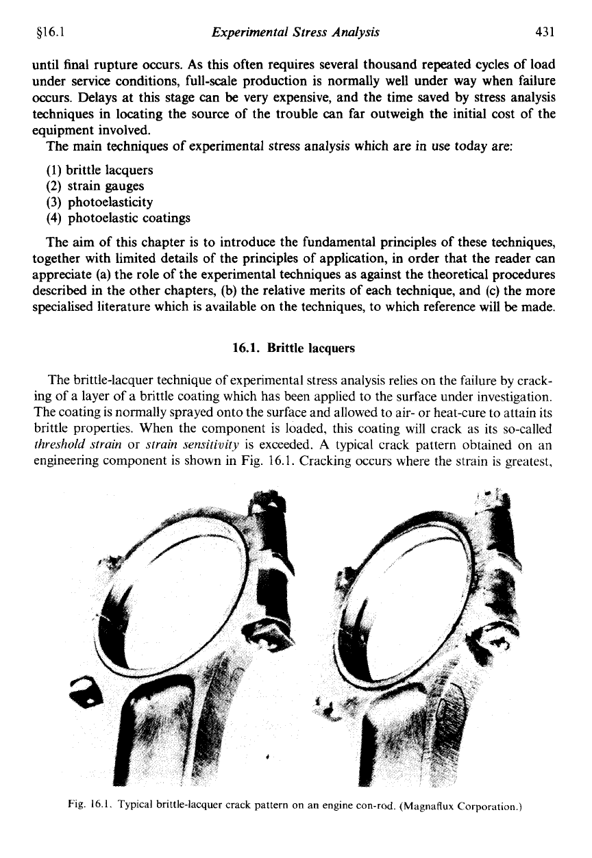
is exceeded. A typical crack pattern obtained on an
engineering component is shown in Fig.
16.1.
Cracking occurs where the strain is greatest,
Fig.
16.1. Typical brittle-lacquer crack pattern on an engine con-rod. (Magnaflux Corporation.)
432
Mechanics
of
Materials
$16.1
so
that an immediate indication is given
of
the presence of stress concentrations. The cracks
also indicate the directions
of
maximum strain at these points since they are always aligned at
right angles to the direction
of
the maximum principal tensile strain. The method is thus
of
great value in determining the optimum positions in which to place strain gauges (see $16.2) in
order
to
record accurately the measurements
of
strain in these directions.
The brittle-coating technique was first used successfully in
1932
by Dietrich and Lehr in
Germany despite the fact that references relating
to
observation of the phenomenon can be
traced back to Clarke’s investigations of tubular bridges in
1850.
The most important
advance in brittle-lacquer technology, however, came in the United States in
193741
when
Ellis, De Forrest and Stern produced a series of lacquers known as “Stresscoat” which, in a
modified form, remain widely used in the world today.
There are many every-day examples of brittle coatings which can be readily observed by the
reader to exhibit cracks indicating local yielding when the strain is suficiently large, e.g.
cellulose, vitreous or enamel finishes. Cellulose paints, in fact, are used by some engineering
companies as a brittle lacquer on rubber models where the strains are quite large.
As
an interesting experiment, try spraying a comb with several thin coats of hair-spray
lacquer, giving each layer an opportunity to dry before application of the next coat. Finally,
allow the whole coating several hours to fully cure; cracks should then become visible when
the comb
is
bent between your fingers.
In engineering applications a little more care is necessary in the preparation of the
component and application
of
the lacquer, but the technique remains a relatively simple and
hence attractive one. The surface of the component should
be
relatively smooth and clean,
standard solvents being used to remove all traces
of
grease and dirt. The lacquer can then be
applied, the actual application procedure depending on the type
of
lacquer used. Most
lacquers may
be
sprayed or painted onto the surface, spraying being generally more favoured
since this produces
a
more uniform thickness of coating and allows a greater control of the
thickness. Other lacquers, for example, are in wax or powder form and require pre-heating of
the component surface in order that the lacquer will melt and run over the surface. Optimum
coating thicknesses depend on the lacquer used but are generally of the order of
1
mm.
In order to determine the strain sensitivity of the lacquer, and hence to achieve an
approximate idea of the strains existing in the component, it is necessary to coat calibration
bars at the same time and in exactly the same manner as the specimen itself. These bars are
normally simple rectangular bars which fit into the calibration jig shown in Fig. 16.2 to form
a simple cantilever with an offset cam at the end producing a known strain distribution along
the cantilever length. When the lacquer on the bar is fully cured, the lever on the cam
is
moved
forward to depress the end
of
the bar by a known amount, and the position at which the
cracking of the lacquer begins gives the strain sensitivity when compared with the marked
strain scale. This enables quantitative measurements of strain levels to be made on the
components under test since if, for example, the calibration sensitivity is shown to be
800
microstrain (strain
x
lop6),
then the strain at the point on the component at which cracks
first appear is also
800
microstrain.
This type of quantitative measurement is generally accurate to no better than
10-20
%,
and
brittle-lacquer techniques are normally used
to
locate the
positions
of stress maxima, the
actual values then being determined by subsequent strain-gauge testing.
Loading is normally applied to the component in increments, held for a few minutes and
released to zero prior to application of the next increment; the time interval between
increments should
be
several times greater than that of the loading cycle. With this procedure
