Hearn E.J. Mechanics of Materials. Volume 1
Подождите немного. Документ загружается.

§16.19
Experimental Stress Analysis
453
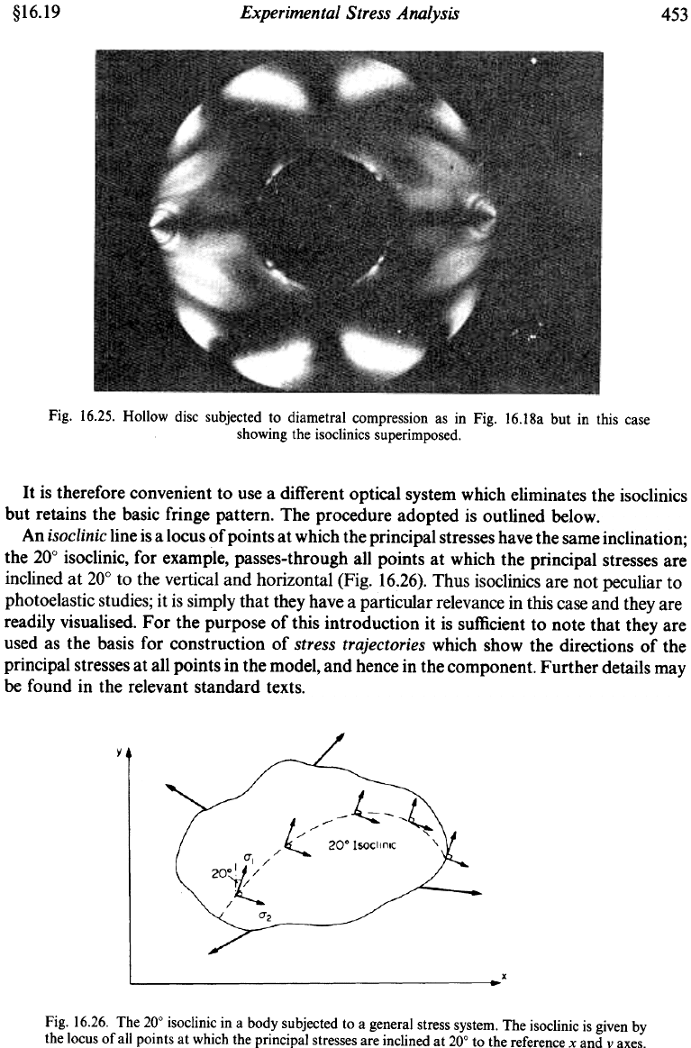
Fig. !6.25. Hollow disc subjected to diametra! compression as in Fig. !6.!8a but in this case
showing the isoc!inics superimposed.
It is therefore convenient to use a different optical system which eliminates the isoclinics
but retains the basic fringe pattern. The procedure adopted is outlined below.
An isoclinic line is a locus of points at which the principal stresses have the same inclination;
the 20° isoclinic, for example, passes-through all points at which the principal stresses are
inclined at 20° to the vertical and horizontal (Fig. 16.26). Thus isoclinics are not peculiar to
photoelastic studies; it is simply that they have a particular relevance in this case and they are
readily visualised. For the purpose of this introduction it is sufficient to note that they are
used as the basis for construction of stress trajectories which show the directions of the
principal stresses at all points in the model, and hence in the component. Further details may
be found in the relevant standard texts.
Fig. 16.26. The 20° isoclinic in a body subjected to a general stress system. The isoclinic is given by
the locus of all points at which the principal stresses are inclined at 20° to the reference x and vaxes.

454
Mechanics
of
Materials
$1 6.20
To prevent the isoclinics interfering with the analysis of stress magnitudes represented by
the basic fringe pattern, they are removed optically by inserting quarter-wave plates with
their axes at 45’
to
those of the polariser and analyser as shown in Fig. 16.24. These eliminate
all unidirectional properties
of
the light by converting it into
circularly polarised
light. The
amount of interference between the component rays emerging from the model, and hence the
fringe patterns, remains unchanged and is now clearly visible in the absence
of
the isoclinics.
16.20.
Stress separation procedures
The photoelastic technique has been shown to provide principal stress difference and hence
maximum shear stresses at all points in the model, boundary stress values and stress
directions. It has also been noted that there are occasions where the separate values of the
principal stresses are required at points other than at the boundary, e.g. in the design of
components using brittle materials. In this case it is necessary to employ one of the many
stress separation
procedures which are available. It is beyond the scope of this section to
introduce these in detail, and full information can
be
obtained if desired from standard
texts.“,
9.
l)
The principal techniques which find most application are (a) the oblique
incidence method, and (b) the shear slope or “shear difference” method.
16.21.
Three-dimensional photoelasticity
In the preceding text, reference has been made to models of uniform thickness, i.e. two-
dimensional models. Most engineering problems, however, arise in the design of components
which are three-dimensional. In such cases the stresses vary not only as
a
function of the
shape in any one plane but also throughout the “thickness” or third dimension. Often a
proportion
of
the more simple three-dimensional model
or
loading cases can be represented
by equivalent two-dimensional systems, particularly if the models are symmetrical, but there
remains a greater proportion which cannot be handled by the two-dimensional approach.
These, however, can also
be
studied using the photoelastic method by means of the so-called
stress-jireezing
technique.
Three-dimensional photoelastic models constructed from the same birefringent material
introduced previously are loaded, heated to a critical temperature and cooled very slowly
back to room temperature. It is then found that a fringe pattern associated with the elastic
stress distribution in the component has been locked or “frozen” into the model. It is then
possible to cut the model into thin slices of uniform thickness, each slice then being examined
as if it were a two-dimensional model. Special procedures for model manufacture, slicing
of
the model and fringe interpretation are required, but these are readily obtained with practice.
16.22.
Reflective coating technique(I2’
A
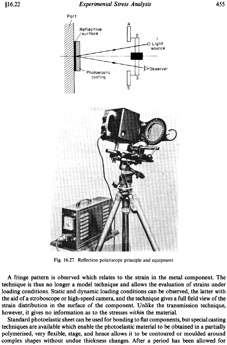
special adaptation of the photoelastic technique utilises a thin sheet of photoelastic
material which is bonded onto the surface
of
a metal component using a special adhesive
containing an aluminium pigment which produces a reflective layer. Polarised light is
directed onto the photoelastic coating and viewed through an analyser after reflection
off
the
metal surface using
a
r&ction
poluriscope
as shown in Fig. 16.27.
Experimental Stress Analysis
§16.22
455
Fig. 16.27. Reflection polariscope principle and equipment.
A fringe pattern is observed which relates to the strain in the metal component. The
technique is thus no longer a model technique and allows the evaluation of strains under
loading conditions. Static and dynamic loading conditions can be observed, the latter with
the aid of a stroboscope or high-speed camera, and the technique gives a full field view of the
strain distribution in the surface of the component. Unlike the transmission technique,
however, it gives no information as to the stresses within the material.
Standard photoelastic sheet can be used for bonding to flat components, but special casting
techniques are available which enable the photoelastic material to be obtained in a partially
polymerised, very flexible, stage, and hence allows it to be contoured or moulded around
complex shapes without undue thickness changes. After a period has been allowed for
456
Mechanics
of’
Materials
$1
6.23
complete polymerisation to occur in the moulded position, the sheet is removed and bonded
firmly back into place with the reflective adhesive.
The reflective technique is particularly useful for the observation of service loading
conditions over wide areas of structure and is often used to highlight the stress concentration
positions which can subsequently become the subject of detailed strain-gauge investigations.
16.23.
Other methods
of
strain measurement
In addition to the widely used methods of experimental stress analysis or strain
measurement covered above, there are a number of lesser-used techniques which have
particular advantages in certain specialised conditions. These techniques can
be
referred to
under the general title of grid methods, although in some cases a more explicit title would
be
“interference methods”.
The standard
grid technique
consists of marking a grid, either mechanically or chemically,
on the surface of the material under investigation and measuring the distortions of this grid
under strain.
A
direct modification of this procedure, known as the
“replica” technique,
involves the firing of special pellets from a gun at the grid both before and during load. The
surface of the pellets are coated with “Woods metal” which is heated in the gun prior to firing.
Replicas of the undeformed and deformed grids are then obtained in the soft metal on contact
with the grid-marked surface. These are viewed in a vernier comparison microscope to obtain
strain readings.
A further modification of the grid procedure, known as the
moirC technique,
superimposes
the deformed grid on an undeformed master (or vice versa). An interference pattern, known
as
moire fringes,
similar to those obtained when two layers of net curtain are superimposed,
is produced and can be analysed to yield strain values.
X-rays
can be used to obtain surface strain values from measurements of crystal lattice
deformation.
Acoustoelasticity,
based on a principle similar to photoelasticity but using
polarised ultrasonic sound waves, has been proposed but is not universally accepted to date.
Holography,
using the laser as a source of coherent light, and again relying on the
interference obtained between holograms of deformed and undeformed components, has
recently created considerable interest, but none of these techniques appear at the moment to
represent a formidable challenge to the major techniques listed earlier.
Bibliography
1.
A.
J.
Durelli,
E.
A.
Phillips and
C.
H. Tsao,
Analysis of Stress and Strain,
McGraw-Hill, New York,
1958.
2.
Magnaflux Corporation,
Principles of Stresscoat.
3.
E.
J.
Hearn,
Brittle Lacquersfor Strain Measurement,
Merrow Publishing Co., Watford, England,
1971.
4.
C. C. Perry and H.
P.
Lissner,
Strain Gauge Primer,
McGraw-Hill, New York.
5.
T.
Potma,
Strain Gauges,
Iliffe, London,
1967.
6.
E.
J.
Hearn,
Strain Gauges,
Merrow Publishing
Co.,
Watford, England,
1971.
7.
R. Murray and
P.
Stein,
Strain Gauge Techniques,
M.I.T. Press, Cambridge, Mass.,
1956.
8.
E. J. Hearn,
Photoelasticity,
Merrow Publishing Co., Watford, England,
1971.
9.
M.
M. Frocht,
Photoelasticity,
vols. I and 11, Wiley,
1961.
10.
H. T. Jessop and
F.
C. Harris,
Photoelasticity,
Cleaver-Hume,
1949.
11.
E.
G.
Coker and
L.
N.
G.
Filon,
Photoelasticity,
Cambridge University Press,
1957.
12.
F. Zandman,
S.
Redner, J. W. Dally,
Photoelastic Coatings
Iowa State/S.E.S.A.
1977.
13.
J.
Pople/B.S.S.M.
Strain Measurement Reference
Book.
B.S.S.M.
Newcastle, England.
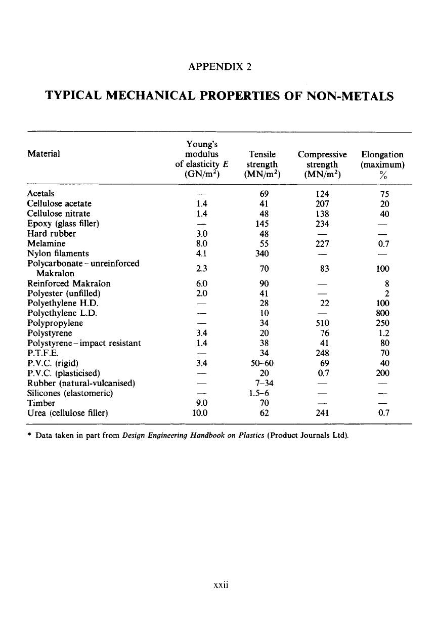
APPENDIX
2
TYPICAL MECHANICAL PROPERTIES
OF
NON-METALS
Material
Young’s
modulus Tensile Compressive Elongation
of
elasticity
E
strength strength (maximum)
(GN/mz) (MN/mz) (MN/mZ)
%
Acetals
Cellulose acetate
Cellulose nitrate
Epoxy (glass filler)
Hard rubber
Melamine
Nylon filaments
Polycarbonate
-
unreinforced
Makralon
Reinforced Makralon
Polyester (unfilled)
Polyethylene
H.D.
Polyethylene
L.D.
Polypropylene
Polystyrene
Polystyrene
-
impact resistant
P.T.F.E.
P.V.C. (rigid)
P.V.C. (plasticised)
Rubber (natural-vulcanised)
Silicones (elastomeric)
Timber
Urea (cellulose filler)
-
1.4
1.4
3.0
8.0
4.1
2.3
6.0
2.0
-
-
3.4
1.4
3.4
-
9.0
10.0
69
41
48
145
48
55
340
70
90
41
28
10
34
20
38
34
50-60
20
7-34
1.5-6
70
62
1
24
207
138
234
221
-
83
-
22
510
76
41
248
69
0.7
-
-
241
75
20
40
-
0.7
100
8
2
100
800
250
1.2
80
70
40
200
-
-
0.7
*
Data taken
in
part
from
Design Engineering
Handbook
on
Plastics
(Product
Journals
Ltd).
xxii

APPENDIX
3
OTHER PROPERTIES
OF
NON-METALS*
Material
Acetal
Acrylic
Nylon
66
Polycarbonate
Polyethylene
LD
Polyethylene
HD
Polypropylene
Polystyrene
PTFE
PVC
EPOXY
Melamine
Phenolic
Polyesterjglass
Silicone
Urea
Organic
Solvents
X
Varies
Varies
X
X
X
X
Varies
Varies
X
X
X
X
x
-0
x
-0
x
-0
Chemical resistance
Acids
Weak
X
X
X
X
X
X
X
X
X
X
X
X
X-0
0
X-0
X-0
Strong
00
X-0
00
0
X00
X-0
X-0
X-0
X-0
00
000
00
00
00
X
X
Alkalis
Weak
X
X
X
x
-0
X
X
X
X
X
X
X
X
(roo
0
0-00
(Mo
Strong
X
X
X
00
X
X
X
X
X
X
0
0
00
00
00
00
x
-
Resistant,
0
-slightly attacked,
00
-markedly attacked
Max.
useful
temp.
('C)
90
90
150
120
90
120
150
95
240
80
430
100-200
200
250
180
90
*
Data taken
from
Design Engineering Handbook on Plastics. (Product Journals Ltd).
xxiii

INDEX
A.C. system 443
Acoustic gauge 444
Acoustoelasticity 456
Active gauge
436, 440, 442, 443
Allowable stresses 308
Area
first moment
of
67
second moment of 62, 68
Auto frettage 233
Axis neutral 66
Balanced circuit 437
Balanced section 72
Beams
bending stress in 64
built-in 140-147
cantilever
97, 98,
101,
109, 110
continuous
115
curved 284
shear stress in 154166
circular 66
moment 41-56
of beams 62-79
plus direct stress 74
plus torsion 187
simple theory of 64
Bending
Birefringence 446
Boundary stress 429
Brittle materials
Built-in beams 140-147
Bulk modulus 198. 202
8, 402, 404, 412
Calibration 433
Capacitance gauge 444
Carriage spring 309
Carrier frequency system 444
Castigliano 255, 266, 269, 303
Centroid 64, 70
Circular shafts 176-190
Clapeyron’s “three-moment” equation
1
15
Close-coiled spring 299
Combined modulus 29
Complementary energy 257
Complex strain 361
Complex stress 326
Composite beam 70
Compound bars 27
Compound beams 70
Compound shafts 182-184
Compound tubes 224
Concrete 71
reinforced 71
Concrete columns 76, 77
Constants, elastic
3, 9, 361, 363, 267
Continuous beams
11
5
Contraflexure 48
Crack detection 433
Creep 15, 432
Criterion of failure 401
Critical section 72
Crossed set-up 446
Cross-sensitivity 437
Curvature, radius of 62
Cylinders
compound 224
plastic yielding 223
thick 215
thin 198
Dark field 446
D.C. system 443
De Forrest 432
Deflections
bending 92-123
impact 264
shear 269
temperature effects
119
Delta rosette 382
Deviatoric stress 263
Dilatational stresses 386
Direct integration method 97
Distortion energy 385
Distortional stresses 386
Double cantilever 146
Double integration method 89
Ductile materials 8, 14, 402, 404, 41
1
Ductility 4, 8
Dummy gauge 436, 438
Dye-etchant 433
Dynamic strain 434
Eccentric loading 74
Economic section 73
Elastic constants 361, 367
Elastic limit 4
Elastic modulus 3
Elasticity 3
Elongation 8
Encastred (encastre) beams 14&147
Endurance limit 17
Energy method 112
Equivalent modulus 29
Equivalent moment 187
Equivalent torque 187, 188
xxv
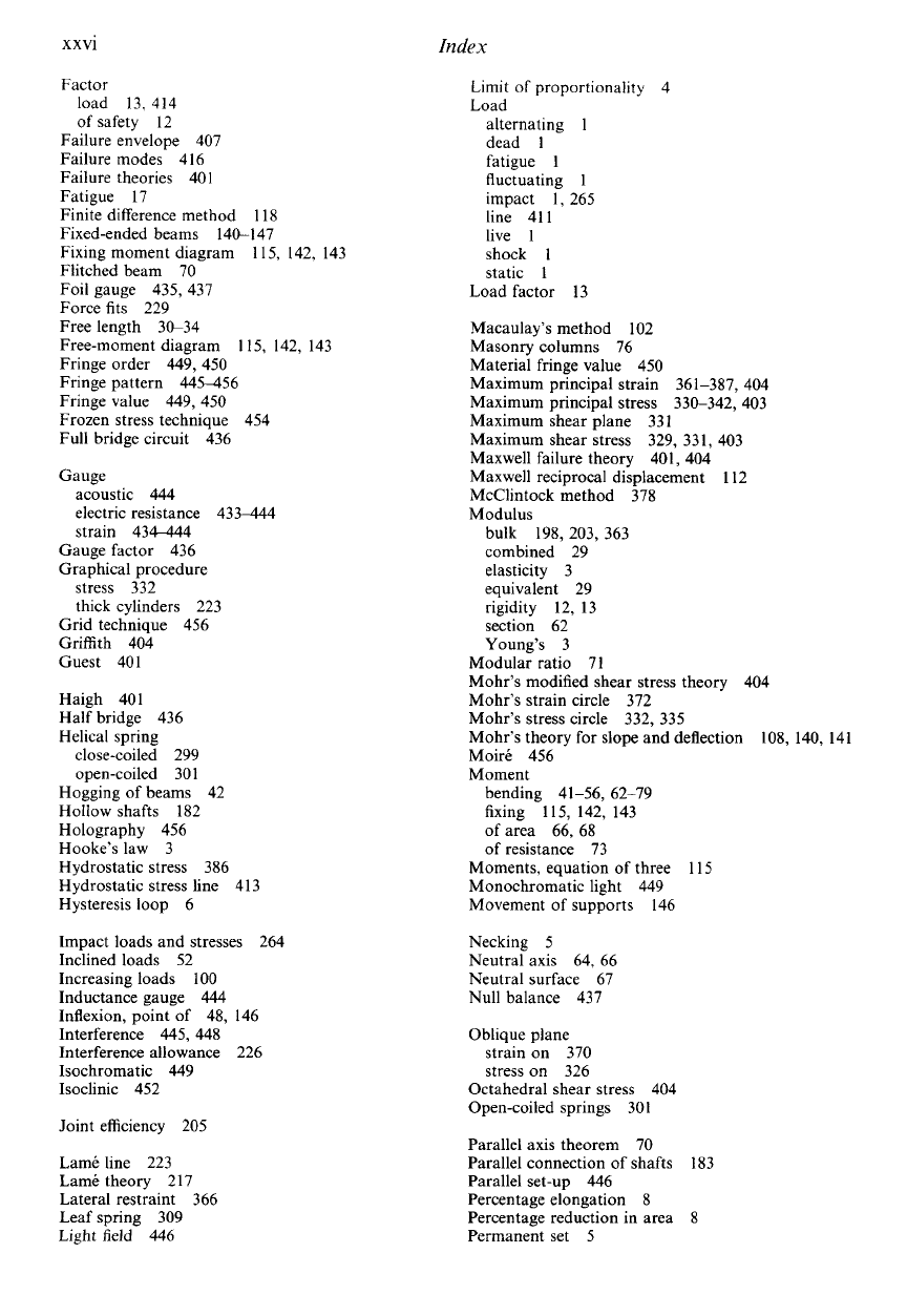
XXVl
Index
Factor
load 13, 414
of safety 12
Failure envelope 407
Failure modes 416
Failure theories 401
Fatigue 17
Finite difference method 118
Fixed-ended beams 140-147
Fixing moment diagram
Flitched beam 70
Foil gauge 435, 437
Force fits 229
Free length 30-34
Free-moment diagram 115, 142, 143
Fringe order 449, 450
Fringe pattern 445456
Fringe value 449,
450
Frozen stress technique 454
Full bridge circuit 436
Gauge
115, 142, 143
acoustic 444
electric resistance 433-444
strain 43-4
Gauge factor 436
Graphical procedure
stress 332
thick cylinders 223
Grid technique 456
Griffith 404
Guest 401
Haigh 401
Half bridge 436
Helical spring
close-coiled 299
open-coiled 301
Hogging of beams 42
Hollow shafts 182
Holography 456
Hooke’s law 3
Hydrostatic stress 386
Hydrostatic stress line 413
Hysteresis loop 6
Impact loads and stresses 264
Inclined loads 52
Increasing loads
100
Inductance gauge 444
Inflexion, point of 48, 146
Interference 445, 448
Interference allowance 226
Isochromatic 449
Isoclinic 452
Joint efficiency 205
Lame line 223
Lame theory 217
Lateral restraint 366
Leaf spring 309
Light field 446
Limit of proportionality
4
Load
alternating
1
dead
1
fatigue
1
fluctuating
1
impact
I,
265
line 411
live
1
shock
1
static
1
Load factor 13
Macaulay’s method
102
Masonry columns 76
Material fringe value 450
Maximum principal strain 361-387, 404
Maximum principal stress 330-342, 403
Maximum shear plane 331
Maximum shear stress 329, 331, 403
Maxwell failure theory 401, 404
Maxwell reciprocal displacement 112
McClintock method 378
Modulus
bulk 198, 203, 363
combined 29
elasticity 3
equivalent 29
rigidity 12, 13
section 62
Young’s 3
Modular ratio 71
Mohr’s modified shear stress theory 404
Mohr’s strain circle 372
Mohr’s stress circle 332, 335
Mohr’s theory
for
slope and deflection
Moirt 456
Moment
108, 140, 141
bending 41-56, 62-79
fixing
115,
142, 143
of area 66, 68
of resistance 73
Moments, equation
of
three 115
Monochromatic light 449
Movement of supports 146
Necking 5
Neutral axis 64, 66
Neutral surface 67
Null balance 437
Oblique plane
strain on 370
stress on 326
Octahedral shear stress 404
Open-coiled springs 301
Parallel axis theorem 70
Parallel connection of shafts 183
Parallel set-up 446
Percentage elongation 8
Percentage reduction in area 8
Permanent set 5
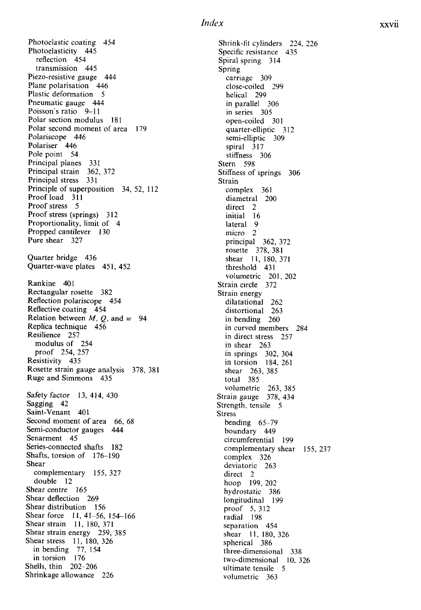
Idex
xxvii
Photoelastic coating 454
Photoelasticity 445
reflection 454
transmission 445
Piezo-resistive gauge 444
Plane polarisation 446
Plastic deformation 5
Pneumatic gauge 444
Poisson's ratio 9-1
1
Polar section modulus 181
Polar second moment of area
Polariscope 446
Polariser 446
Pole point 54
Principal planes 331
Principal strain 362, 372
Principal stress 33
1
Principle of superposition 34, 52, 112
Proof load 31
1
Proof stress
5
Proof stress (springs) 3 12
Proportionality, limit of 4
Propped cantilever 130
Pure shear 327
Quarter bridge 436
Quarter-wave plates 451, 452
Rankine 401
Rectangular rosette 382
Reflection polariscope 454
Reflective coating 454
Relation between
M,
Q,
and
w
94
Replica technique 456
Resilience 257
179
modulus
of
254
proof 254, 257
Resistivity 435
Rosette strain gauge analysis
Ruge and Simmons 435
Safety factor 13, 414, 430
Sagging 42
Saint-Venant 401
Second moment
of
area 66, 68
Semi-conductor gauges 444
Senarment 45
Series-connected shafts 182
Shafts, torsion of 176190
Shear
complementary 155, 327
double 12
378, 381
Shear centre 165
Shear deflection 269
Shear distribution 156
Shear force
11,
41-56, 154-166
Shear strain
11,
180, 371
Shear strain energy 259, 385
Shear stress 11, 180, 326
in bending 77, 154
in torsion 176
Shells, thin 202-206
Shrinkage allowance 226
Shrink-fit cylinders 224. 226
Specific resistance 435
Spiral spring 3 I4
Spring
carriage 309
close-coiled 299
helical 299
in parallel 306
in series 305
open-coiled 301
quarter-elliptic 3 12
semi-elliptic 309
spiral 317
stiffness 306
Stern 598
Stiffness of springs 306
Strain
complex 361
diametral 200
direct 2
initial 16
lateral 9
micro 2
principal 362, 372
rosette 378, 381
shear
I
I,
180,
371
threshold 43
1
volumetric 20
I,
202
Strain circle 372
Strain energy
dilatational 262
distortional 263
in bending 260
in curved members 284
in direct stress 257
in shear 263
in springs 302, 304
in torsion 184, 261
shear 263, 385
total 385
volumetric 263, 385
Strain gauge 378, 434
Strength, tensile 5
Stress
bending 65-79
boundary 449
circumferential 199
complementary shear 155, 237
complex 326
deviatoric 263
direct 2
hoop 199,202
hydrostatic 386
longitudinal 199
proof 5, 312
radial
198
separation 454
shear
11.
180,
326
spherical 386
three-dimensional 338
two-dimensional
IO,
326
ultimate tensile 5
volumetric 363
