Hearn E.J. Mechanics of Materials. Volume 1
Подождите немного. Документ загружается.

816.10
Experimental Stress Analysis
443
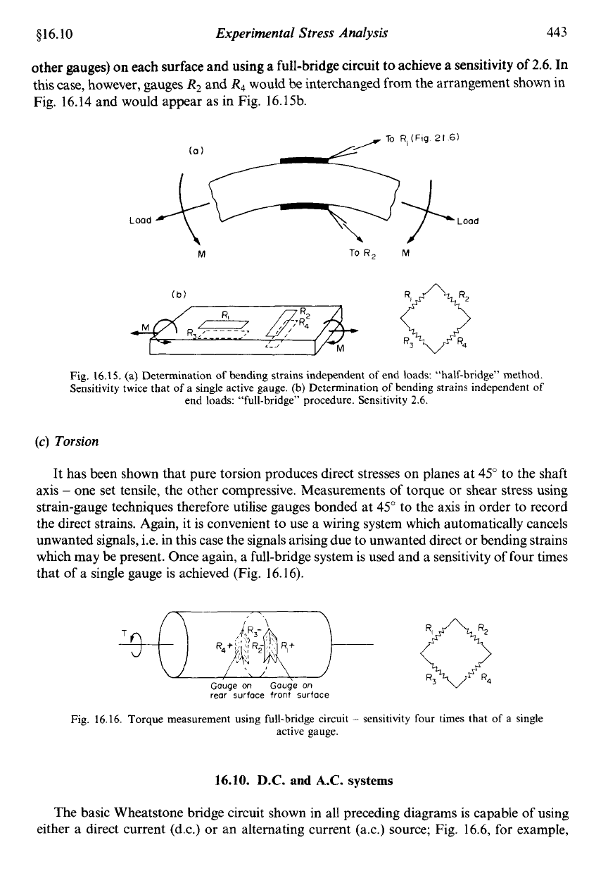
other gauges) on each surface and using a full-bridge circuit
to
achieve
a
sensitivity of
2.6.
In
this case, however, gauges
R2
and
R4
would be interchanged from the arrangement shown
in
Fig. 16.14 and would appear as in Fig. 16.15b.
Lood
M
To
R,
M
V
1.1
Fig.
16.1
5.
(a) Determination of bending strains independent
of
end loads: "half-bridge" method.
Sensitivity twice that of a single active gauge. (b) Determination
of
bending strains independent
of
end loads: "full-bridge'' procedure. Sensitivity
2.6.
(c)
Torsion
It has been shown that pure torsion produces direct stresses on planes at
45"
to the shaft
axis
-
one set tensile, the other compressive. Measurements of torque or shear stress using
strain-gauge techniques therefore utilise gauges bonded at 45" to the axis in order to record
the direct strains. Again, it is convenient
to
use a wiring system which automatically cancels
unwanted signals, i.e. in this case the signals arising due to unwanted direct or bending strains
which may be present. Once again, a full-bridge system is used and a sensitivity of four times
that of a single gauge is achieved (Fig. 16.16).
-+o-
0
Gouge
on
Gouge
on
rear surface front surface
Fig.
16.16.
Torque
measurement using full-bridge circuit
-
sensitivity four times that of a single
active gauge.
16.10.
D.C.
and
A.C.
systems
The basic Wheatstone bridge circuit shown in all preceding diagrams is capable of using
either a direct current (d.c.) or an alternating current (a.c.) source; Fig. 16.6, for example,
444
Mechanics
of
Materials
$16.1
1
subjected
to
shows the circuit excited by means
of
a standard battery (d.c.) source. Figure
16.17,
however,
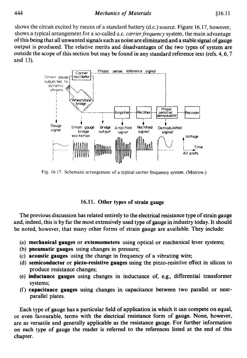
shows a typical arrangement for a so-called ax.
carrier
frequency
system, the main advantage
of
this being that all unwanted signals such as noise are eliminated and a stable signal of gauge
output
is
produced. The relative merits and disadvantages of the two types of system are
outside the scope of this section but may
be
found in any standard reference text (refs.
4,6,7
and
13).
Fig.
16.17.
Schematic arrangement
of
a typical
carrier
frequency
system.
(Merrow.)
16.11.
Other
types
of
strain gauge
The previous discussion has related entirely to the electrical resistance type of strain gauge
and, indeed, this is by far the most extensively used type of gauge in industry today.
It
should
be
noted, however, that many other forms of strain gauge are available. They include:
(a)
mechanical gauges
or
extensometers
using optical or mechanical lever systems;
(b)
pneumatic gauges
using changes in pressure;
(c)
acoustic gauges
using the change in frequency of a vibrating wire;
(d)
semiconductor
or
piezo-resistive gauges
using the piezo-resistive effect in silicon to
(e)
inductance gauges
using changes in inductance of, e.g., differential transformer
(f)
capacitance gauges
using changes in capacitance between two parallel or near-
produce resistance changes;
systems;
parallel plates.
Each type of gauge has a particular field of application in which it can compete on equal,
or even favourable, terms with the electrical resistance form of gauge. None, however,
are as versatile and generally applicable as the resistance gauge. For further information
on each type of gauge the reader is referred to the references listed at the end of this
chapter.
§16.12
Experimental Stress Analysis 445
16.12. Photoelasticity
In recent years, photoelastic stress analysis has become a technique of outstanding
importance to engineers. When polarised light is passed through a stressed transparent
model, interference patterns or fringes are formed. These patterns provide immediate
qualitative information about the general distribution of stress, positions of stress
concentrations and of areas of low stress. On the basis of these results, designs may be
modified to reduce or disperse concentrations of stress or to remove excess material from
areas oflow stress, thereby achieving reductions in weight and material costs. As photoelastic
analysis may be carried out at the design stage, stress conditions are taken into account before
production has commenced; component failures during production, necessitating expensive
design modifications and re-tooling, may thus be avoided. Even when service failures do
occur, photoelastic analysis provides an effective method of failure investigation and often
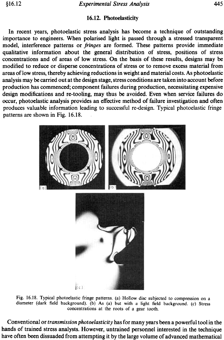
produces valuable information leading to successful re-design. Typical photoelastic fringe
patterns are shown in Fig. 16.18.
Fig. 16.18. Typical photoelastic fringe patterns. (a) Hollow disc subjected to compression on a
diameter (dark field background). (b) As (a) but with a light field background. (c) Stress
concentrations at the roots of a gear tooth.
Conventional or transmission photoelasticity has for many years been a powerful tool in the
hands of trained stress analysts. However, untrained personnel interested in the technique
have often been dissuaded from attempting it by the large volume of advanced mathematical
446
Mechanics
of
Materials
516.13
and optical theory contained in reference texts on the subject. Whilst this theory is, no doubt,
essential for a complete understanding of the phenomena involved and of some of the more
advanced techniques, it is important to accept that a wealth of valuable information can
be
obtained by those who are not fully conversant with all the complex detail.
A
major feature of
the technique is that it allows one to effectively “look into” the component and pin-point
flaws or weaknesses in design which are otherwise difficult or impossible to detect. Stress
concentrations are immediately visible, stress values around the edge
or
boundary of the
model are easily obtained and, with a little more effort, the separate principal stresses within
the model can also be determined.
16.13.
Plane-polarised light
-
basic polariscope arrangements
Before proceeding with the details of the photoelastic technique it is necessary to introduce
the meaning and significance of
plane-polarised light
and its use in the equipment termed
polariscopes
used for photoelastic stress analysis. If light from an ordinary light bulb is passed
through a polarising sheet or
polariser,
the sheet will act like a series
of
vertical slots
so
that
the emergent beam will consist of light vibrating in one plane only: the plane of the slots. The
light is then said to be
plane polarised.
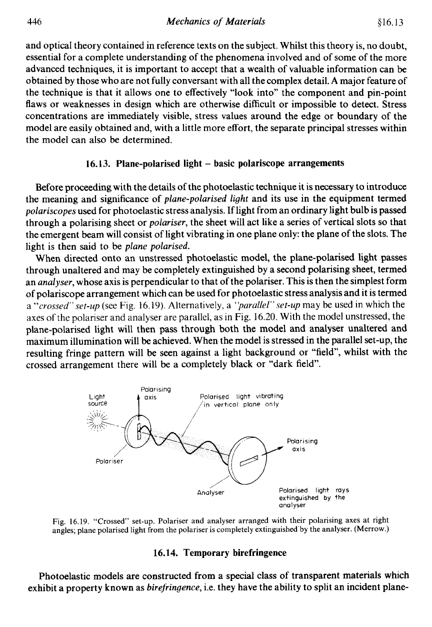
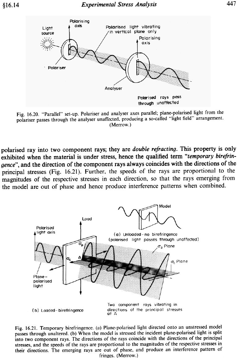
When directed onto an unstressed photoelastic model, the plane-polarised light passes
through unaltered and may be completely extinguished by a second polarising sheet, termed
an
analyser,
whose axis is perpendicular to that of the polariser. This is then the simplest form
of polariscope arrangement which can be used for photoelastic stress analysis and it is termed
a
“crossed”
set-up
(see Fig. 16.19). Alternatively, a
‘parullel”set-up
may be used
in
which the
axes
of
the polariser and analyser are parallel, as in Fig. 16.20. With the model unstressed, the
plane-polarised light will then pass through both the model and analyser unaltered and
maximum illumination will be achieved. When the model is stressed in the parallel set-up, the
resulting fringe pattern will be seen against a light background or “field, whilst with the
crossed arrangement there will
be
a completely black
or
“dark field”.
Polarising
Light Polarised light vibrating
source
t
axis
/in vertical plane only
Polarising
axis
Poloriser
Anulyser Polarised light rays
extinguished by the
analyser
Fig.
16.19.
“Crossed” set-up. Polariser and analyser arranged with their polarising axes at right
angles, plane polarised light
from
the polariser
is
completely extinguished
by
the analyser. (Merrow.)
16.14.
Temporary birefringence
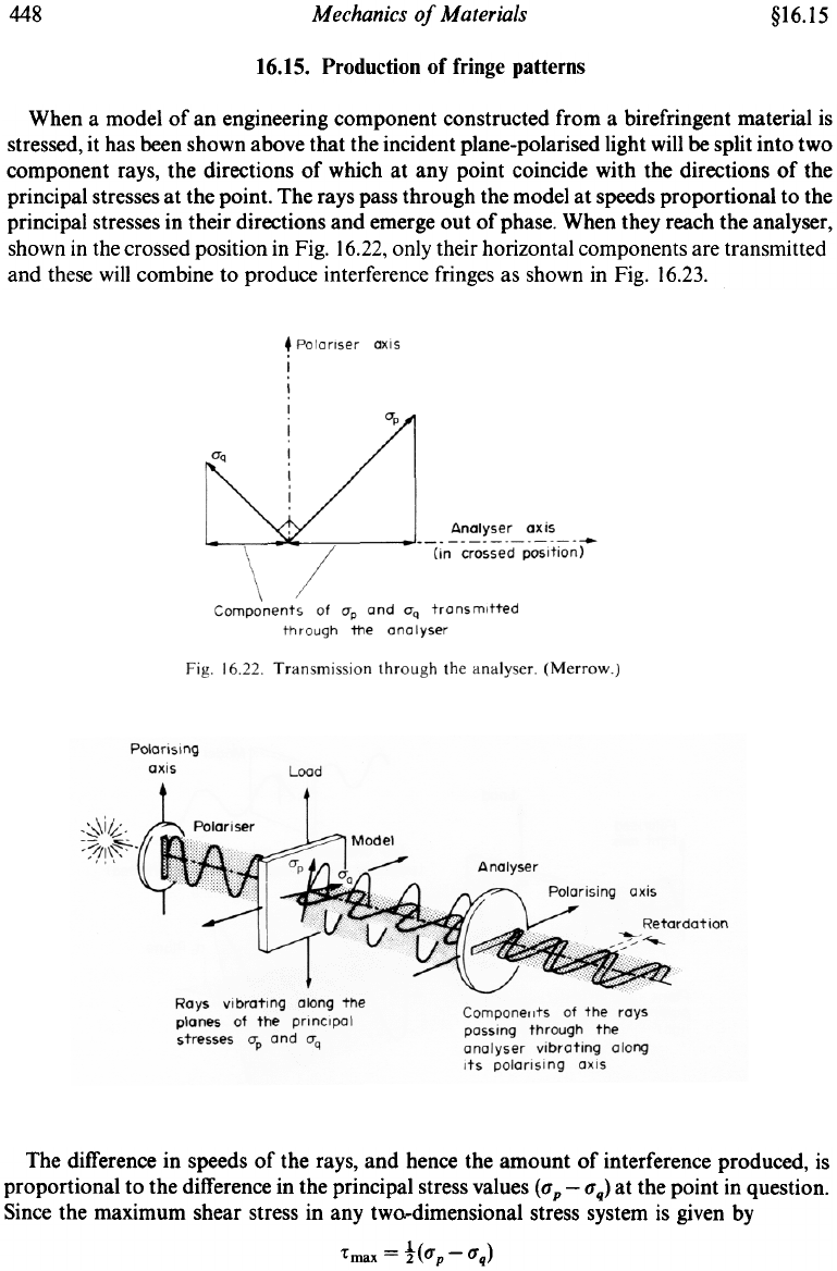
Photoelastic models are constructed from a special class of transparent materials which
exhibit a property known as
birefringence,
i.e. they have the ability to split an incident plane-
Experimental Stress Analysis
447
§16.14
Fig. 16.20. "Paralle\" set-up. Polariser and analyser axes paral1el; plane-polarised light from the
polariser passes through the analyser unaffected, producing a so-cal1ed "light field" arrangement.
(Merrow.)
polarised ray into two component rays; they are double refracting. This property is only
exhibited when the material is under stress, hence the qualified term "temporary birefrin-
gence", and the direction of the component rays always coincides with the directions of the
principal stresses (Fig. 16.21 ). Further, the speeds of the rays are proportional to the
magnitudes of the respective stresses in each direction, so that the rays emerging from
the model are out of phase and hence produce interference patterns when combined.
Fig. 16.21. Temporary birefringence. (a) Plane-polarised lighl direcled onlo an unslressed model
passes through unaltered. (b) When the model is stressed Ihe incidenl plane-polarised light is split
into two component rays. The directions of the rays coincide with the directions of the principal
stresses, and the speeds of the rays are proportional to the magnitudes of Ihe respeclive stresses in
their directions. The emerging rays are out of phase, and produce an interference pattern of
fringes. (Merrow.)
448
Mechanics of Materials
§16.1S
16.15. Production of fringe patterns
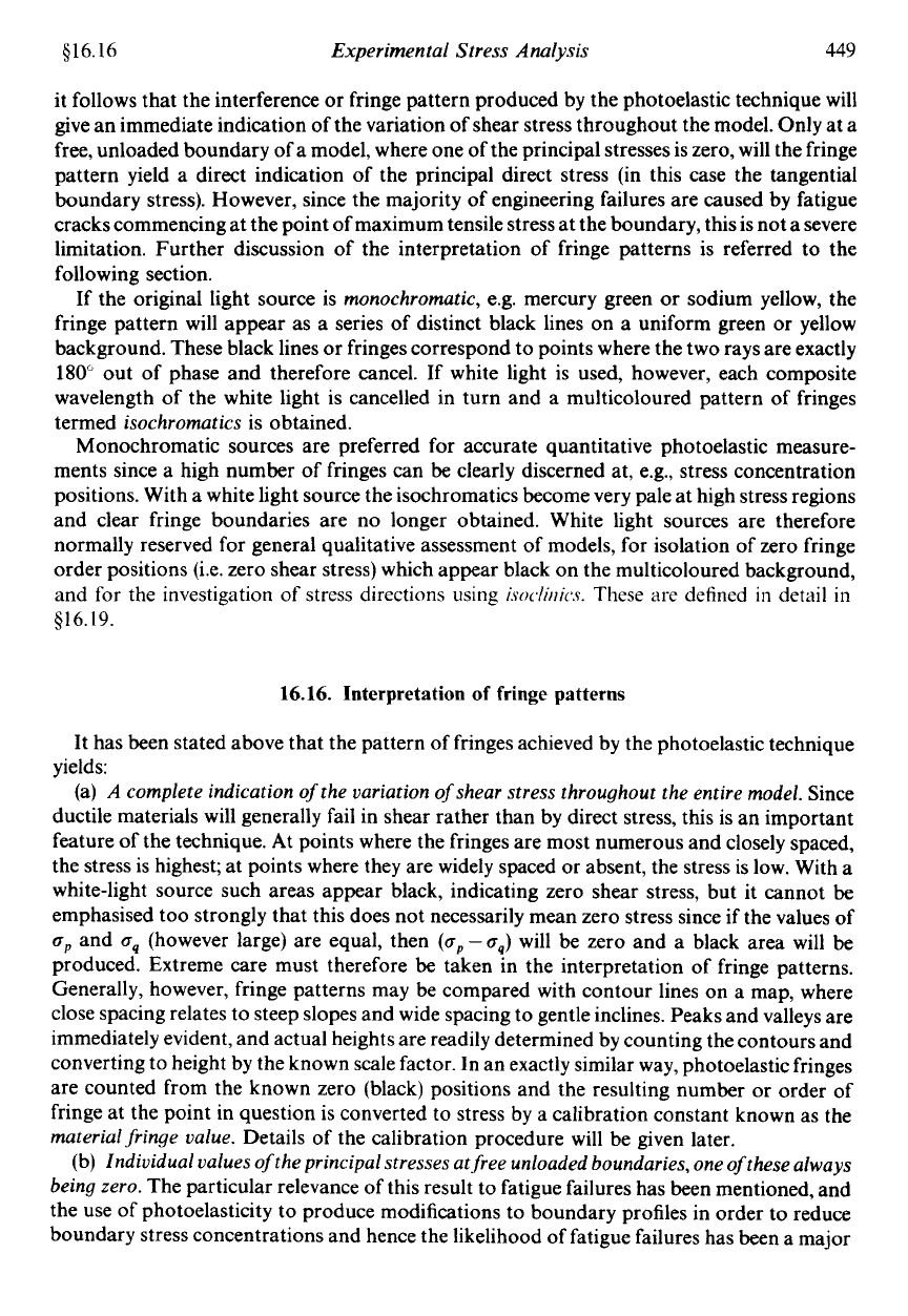
When a model of an engineering component constructed from a birefringent material is
stressed, it has been shown above that the incident plane-polarised light will be split into two
component rays, the directions of which at any point coincide with the directions of the
principal stresses at the point. The rays pass through the model at speeds proportional to the
principal stresses in their directions and emerge out of phase. When they reach the analyser ,
shown in the crossed position in Fig. 16.22, only their horizontal components are transmitted
and these will combine to produce interference fringes as shown in Fig. 16.23.
The difference in speeds of the rays, and hence the amount of interference produced, is
proportional to the difference in the principal stress values ( O" p -O" q) at the point in question.
Since the maximum shear stress in any tw0...dimensional stress system is given by
!max = t(O"p-O"q)
516.16
Experimental Stress Analysis
449
it follows that the interference or fringe pattern produced by the photoelastic technique will
give an immediate indication of the variation of shear stress throughout the model. Only at
a
free, unloaded boundary of a model, where one of the principal stresses is zero, will the fringe
pattern yield a direct indication of the principal direct stress (in this case the tangential
boundary stress). However, since the majority of engineering failures are caused by fatigue
cracks commencing at the point of maximum tensile stress at the boundary, this is not a severe
limitation. Further discussion of the interpretation of fringe patterns is referred to the
following section.
If the original light source is
monochromatic,
e.g. mercury green or sodium yellow, the
fringe pattern will appear as a series of distinct black lines on a uniform green
or
yellow
background. These black lines or fringes correspond to points where the two rays are exactly
180"
out of phase and therefore cancel. If white light is used, however, each composite
wavelength of the white light is cancelled in turn and a multicoloured pattern
of
fringes
termed
isochromatics
is obtained.
Monochromatic sources are preferred for accurate quantitative photoelastic measure-
ments since a high number of fringes can be clearly discerned at, e.g., stress concentration
positions. With a white light source the isochromatics become very pale at high stress regions
and clear fringe boundaries are no longer obtained. White light sources are therefore
normally reserved for general qualitative assessment
of
models, for isolation of zero fringe
order positions (Le. zero shear stress) which appear black on the multicoloured background,
and for the investigation
of
stress directions using
i.soc/i~ii~s.
These are defined
in
detail
in
916.19.
16.16.
Interpretation of fringe patterns
It has been stated above that the pattern of fringes achieved by the photoelastic technique
yields:
(a)
A
complete indication
of
the variation
of
shear stress throughout the entire model.
Since
ductile materials will generally fail in shear rather than by direct stress, this is an important
feature of the technique. At points where the fringes are most numerous and closely spaced,
the stress is highest; at points where they are widely spaced
or
absent, the stress
is
low. With a
white-light source such areas appear black, indicating zero shear stress, but it cannot
be
emphasised too strongly that this does not necessarily mean zero stress since if the values
of
a,,
and
aq
(however large) are equal, then
(a,,
-
oq)
will be zero and a black area will be
produced. Extreme care must therefore
be
taken in the interpretation of fringe patterns.
Generally, however, fringe patterns may
be
compared with contour lines on a map, where
close spacing relates to steep slopes and wide spacing to gentle inclines. Peaks and valleys are
immediately evident, and actual heights are readily determined by counting the contours and
converting to height by the known scale factor. In an exactly similar way, photoelastic fringes
are counted from the known zero (black) positions and the resulting number or order of
fringe at the point in question is converted to stress by a calibration constant known as the
material fringe value.
Details of the calibration procedure will be given later.
(b)
Individual values
of
the principal stresses at free unloaded boundaries, one
of
these always
being zero.
The particular relevance of this result to fatigue failures has been mentioned, and
the use of photoelasticity
to
produce modifications to boundary profiles in order
to
reduce
boundary stress concentrations and hence the likelihood of fatigue failures has been a major
450
Mechanics
of
Materials
$16.17
use of the technique. In addition to the immediate indication of high stress locations, the
photoelastic model will show regions of low stress from which material can
be
conveniently
removed
without weakening the component to effect a reduction in weight and material cost.
Surprisingly, perhaps, a reduction in material at or near a high stress concentration can also
produce a significant reduction in maximum stress. Re-design can be carried out on a “file-it-
and-see’’ basis, models being modified or re-shaped within minutes in order to achieve the
required distribution of stress.
Whilst considerable valuable qualitative information can
be
readily obtained from
photoelastic models without any calculations at all, there are obviously occasions where the
precise values of the stresses are required. These are obtained using the following basic
equation of photoelasticity,
nf
t
ap-aq
=
-
(16.5)
where
op
and
oq
are the values of the maximum and minimum principal stresses at the point
under consideration,
n
is the fringe number
or
fringe order
at the point,
f
is the
material fringe
value
or
coeficient,
and
t
is the model thickness.
Thus with a knowledge of the material fringe value obtained by calibration as described
below, the required value
of
(op
-
cq)
at any point can
be
obtained readily by simply counting
the fringes from zero to achieve the value
n
at the point in question and substitution in the
above relatively simple expression.
Maximum shear stress or boundary stress values are then easily obtained and the
application of one of the so-called
stress-separation
procedures will yield the separate value of
the principal stress at other points in the model with just a little more effort. These may
be
of
particular interest in the design of components using brittle materials which are known to be
relatively weak under the action
of
direct stresses.
16.17.
Calibration
The value of
which, it will
be
remembered, is analogous to the height scale
for
contours
on a survey map, is determined by a simple calibration experiment in which the known stress
at some point in a convenient model is plotted against the fringe value at that point under
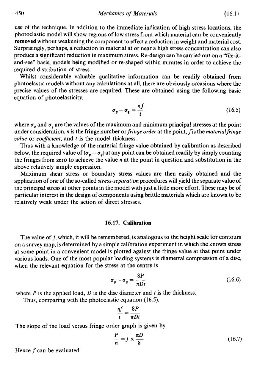
various loads. One of the most popular loading systems is diametral compression
of
a disc,
when the relevant equation
for
the stress at the centre is
where
P
is the applied load,
D
is the disc diameter and
t
is the thickness.
Thus, comparing with the photoelastic equation (1
6.5),
nf
-
8P
--
-
t
zDt
The slope of the load versus fringe order graph is given by
P
nD
-=fxs
n
Hence
f
can be evaluated.
(16.6)
(16.7)
$16.18
Experimental Stress Analysis
45
1
16.18. Fractional fringe order determination
-
compensation techniques
The accuracy of the photoelastic technique is limited, among other things, to the accuracy
with which the fringe order at the point under investigation can
be
evaluated. It is not
sufficiently accurate to count to the nearest whole number of fringes, and precise
determination
of
fractions of fringe order at points lying between fringes is required.
Conventional methods for determining these fractions of fringe order are termed
compens-
ation techniques
and allow estimation of fringe orders to an accuracy of one-fiftieth of a
fringe. The two methods most often used are the Tardy and Senarmont techniques. Before
either technique can be adopted, the directions of the polariser and analyser must be aligned
with the directions of the principal stresses at the point. This is achieved by rotating both
units together in the plane polariscope arrangement until an
p isoclinic
($16.19) crosses the
point. In most modern polariscopes facilities exist to couple the polariser and analyser
together in order to facilitate synchronous rotation. The procedure for the two techniques
then varies slightly.
(a)
Tardy method
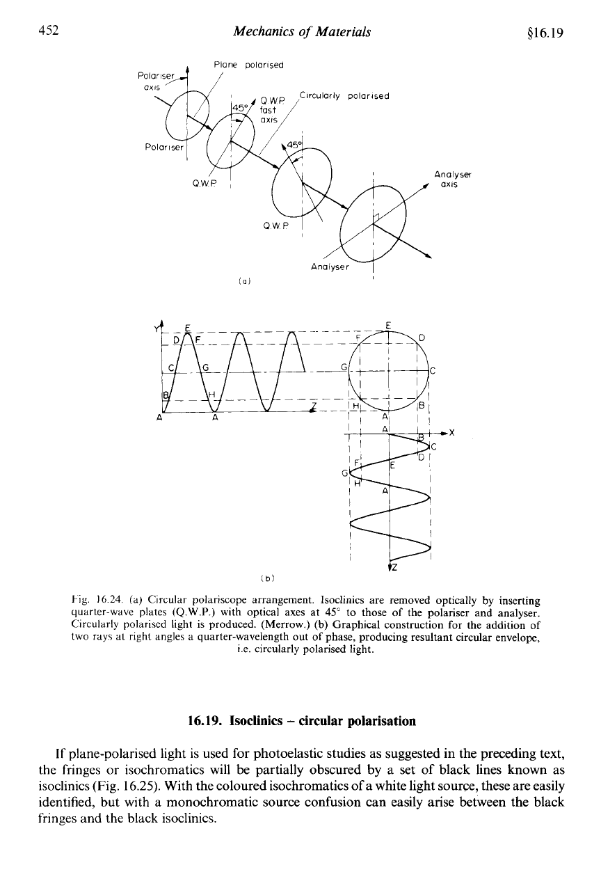
Quarter-wave plates are inserted at 45" to the polariser and analyser as the dark field
circular polariscope set-up of Fig. 16.24. Normal fringe patterns will then
be
visible in the
absence
of
isoclinics.
(b)
Senarmont method
The polariser and analyser are rotated through a further
45"
retaining the dark field, thus
moving the polarising axes at
45"
to the principal stress directions at the point. Only one
quarter-wave plate is then inserted between the model and the analyser and rotated to again
achieve a dark field. The normal fringe pattern is then visible as with the Tardy method.
Thus, having identified the integral value
n
of the fringe order at the point, i.e. between
1
and
2,
or
2
and
3,
for instance, the fractional part can now be established for both methods in
the same way.
The analyser is rotated on its own to produce movement of the fringes. In particular, the
nearest
lower order
of fringe is moved to the point of interest and the angle
8
moved by the
analyser recorded.
eo
The fringe order at the chosen point is then
n+-
180"'
N.B.-Rotation of the analyser in the opposite direction
4°
would move the nearest
highest
order
fringe
(n
+
1)
back to the point. In this case the fringe order at the point would be
4
@+I)---
180
It can be shown easily by trial that the sum of the two angles
8
and
4
is always
180".
prefer to use Tardy, others to use Senarmont.
There is little to choose between the two methods in terms of accuracy; some workers
452
Mechanics
of
Materials
516.19
Analyser
axis
(b)
l-
ig.
16.24.
(a) Circular polariscope arrangement. Isoclinics are removed optically by inserting
quarter-wave plates
(Q.W.P.)
with optical axes at
45"
to those of the polariser and analyser.
Circularly polariscd light is produced. (Merrow.)
(b)
Graphical construction for the addition of
two
rays at
right
angles a quarter-wavelength out
of
phase, producing resultant circular envelope,
i.e. circularly polarised light.
16.19.
Isoclinics
-
circular polarisation
If
plane-polarised light is used for photoelastic studies as suggested in the preceding text,
the fringes or isochromatics
will
be partially obscured by a set of black lines known as
isoclinics (Fig.
16.25).
With the coloured isochromatics
of
a white light sourw, these are easily
identified, but with a monochromatic source confusion can easily arise between the black
fringes and the black isoclinics.
