Hearn E.J. Mechanics of Materials. Volume 1
Подождите немного. Документ загружается.

Complex
Stresses
353
Fig.
13.32
Example
13.6
(B)
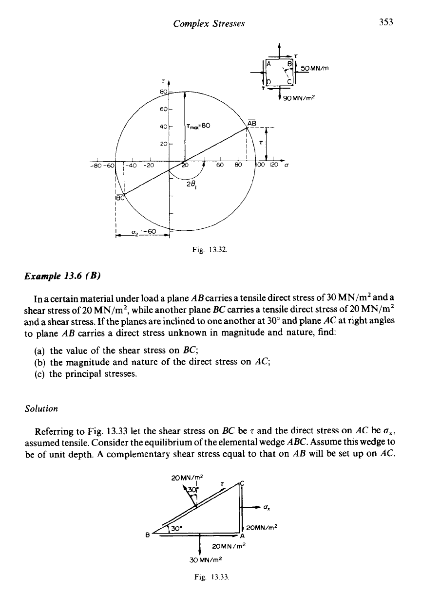
In a certain material under load a plane ABcarries a tensile direct stress of
30
MN/mZ and a
shear stress of
20
MN/m2, while another plane
BC
carries a tensile direct stress
of
20
MN/m2
and a shear stress.
If
the planes are inclined to one another at
30"
and plane
AC
at right angles
to plane
AB
carries a direct stress unknown in magnitude and nature, find:
(a) the value
of
the shear stress on
BC;
(b) the magnitude and nature of the direct stress on
AC;
(c)
the principal stresses.
Solution
Referring to Fig.
13.33
let the shear stress on
BC
be
5
and the direct stress on
AC
be
ox,
assumed tensile. Consider the equilibrium of the elemental wedge
ABC.
Assume this wedge
to
be of unit depth.
A
complementary shear stress equal to that on
AB
will
be
set up on
AC.
X)
MN/m2
Fig.
13.33
354
Mechanics
of
Materials
(a)
To find
2,
resolve forces vertically:
30x(ABx l)+20x(ACx
1)=20x(BCxl)cos30"+~x(BCx
l)sin30"
Now AB
=
BC cos 30 and AC
=
BC sin 30
..
30 x BCcos 30 +20 x BCsin30
=
20 x BCcos30+
7
x BCsin30
1
2
30- +20
x
-
=
20
x
-
+
7
x
-
1
J3
2
2
J3
2
30J3
+
20
=
20J3
+
7
7
=
lOJ3
+
20
=
37.32 MN/mZ
..
The required shear stress is 37.32 MN/m2.
(b)
To find
ox,
resolve forces horizontally:
20x(ABx l)+a,x(ACx
l)+~x(BCxl)cos30"=20x(BCx
l)sin30"
20xBCcos30"+a,xBCsin30"+~xBCcos30"
=20xBCsin30"
1 J3 1
2 2 2
20
x
-
+
u,
x
-+
7
x
-
=
20 x
-
J3
2
20J3
-k
B,
+
J3
x
37.32
=
10
..
B,
=
10- J3
x
57.32
=
10-99.2
=
-
89.2 MN/m2, i.e. compressive
(c) The principal stresses are now given
by
fJ1,z
=
f
(a,
+
Cy)
f
fJC(a,
-
+
4?&1
=
+{(
-
89.2
+
30)
k
J[(
-
89.2
-
30)2 +4 x 2023)
=
5{-5.92+J[(-11.92)2+16]}
=
5[
-5.92+ ,/l58]
=
5[
-
5.92
12.571
..
a1
=
33.25MN/mZ
c2
=
-
92.45 MN/m2
The principal stresses are 33.25 MN/m2 tensile and 92.45 MN/m2 compressive.
Example
13.7
(B)
A
hollow steel shaft
of
100 mm external diameter and
50
mm internal diameter transmits
0.75
MW at 500 rev/min and is also subjected to an axial end thrust of
50
kN. Determine the
maximum bending moment which can
be
safely applied in conjunction with the applied
torque and thrust if the maximum compressive principal stress
is
not to exceed 100 MN/m2
compressive. What will then be the value
of:
(a) the other principal stress;
(b)
the maximum shear stress?
Complex
Stresses
Solution
355
The torque on the shaft may be found from
power
=
T
x
o
0.75
x
lo6
x
60
2a
x
500
..
T=
=
14.3
x
lo3
=
14.3
kNm
The shear stress in the shaft at the surface is then given by the torsion theory
Tz
-
J
=E
TR
14.3
x
103
x
50
x
10-3
x
2
.5=-=
J
a(504
-
254)10-12
=
0.78
x
lo8
=
78
MN/m2
The direct stress resulting from the end thrust is given by
load
-5Ox
lo3
area
n(502
-
252)
gd=--
-
=
-
8.5
x
lo6
=
-8.5MN/m2
The bending moment to be applied will produce a direct stress in the same direction as
o,,.
Thus the total stress in the
x
direction is
6,
=
bb
+
bd
the greatest value of
0,
being obtained where the bending stress is of the same sign as the end
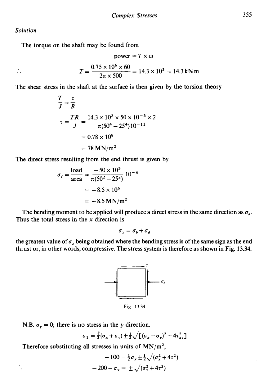
thrust or, in other words, compressive. The stress system is therefore as shown in Fig.
13.34.
Fig.
13.34
N.B.
oy
=
0;
there
is
no stress in the
y
direction.
61
=
+47:,1
Therefore substituting all stresses in units of MN/m2,
-
100
=
$7,
&
)J(aZ
+
4.52)
..
-
200
-
6,
=
f
J(6:
+
4.52)
356
Mechanics
of
Materials
..
Therefore stress owing to bending
~i,
=
gX
-
od
=
-
39.2
-
(-
8.5)
=
-
30.7
MN/m2
(i.e. compressive)
But from bending theory
MY
30.7
x
lo6
x
n(504-254)10-'2
o*
=
~
I
..
M=
50~10-~x4
=
2830
Nm
=
2.83
kNm
i.e. the bending moment which can be safely applied is
2.83
kN
m.
(a) The other principal stress
62
=
$ax
+$J(CJZ
+
472)
=
-
19.6 +$J(39.2'
+
24320)
=
-
19.6+
80.5
=
60.9
MN/m2
(tensile)
(b) The maximum shear stress is given by
7max
=
-az)
=
$(
-
100
-
60.9)
=
-
80.45
MN/m2
i.e. the maximum shear stress is
80.45
MN/mZ.
Example
13.8
A
beam of symmetrical I-section is simply supported at each end and loaded at the centre of
its
3
m span with a concentrated load of
100
kN. The dimensions of the cross-section are:
flanges
150
mm wide by
30
mm thick; web
30
mm thick; overall depth
200
mm.
For the transverse section at the point of application of the load, and considering a point at
the top of the web where it meets the flange, calculate the magnitude and nature of the
principal stresses. Neglect the self-mass of the beam.
Complex
Stresses
357
Solution
At any section of the beam there will
be
two sets of stresses acting simultaneously:
(1) bending stresses
(2) shear stresses
together with their associated complementary shear stresses
of
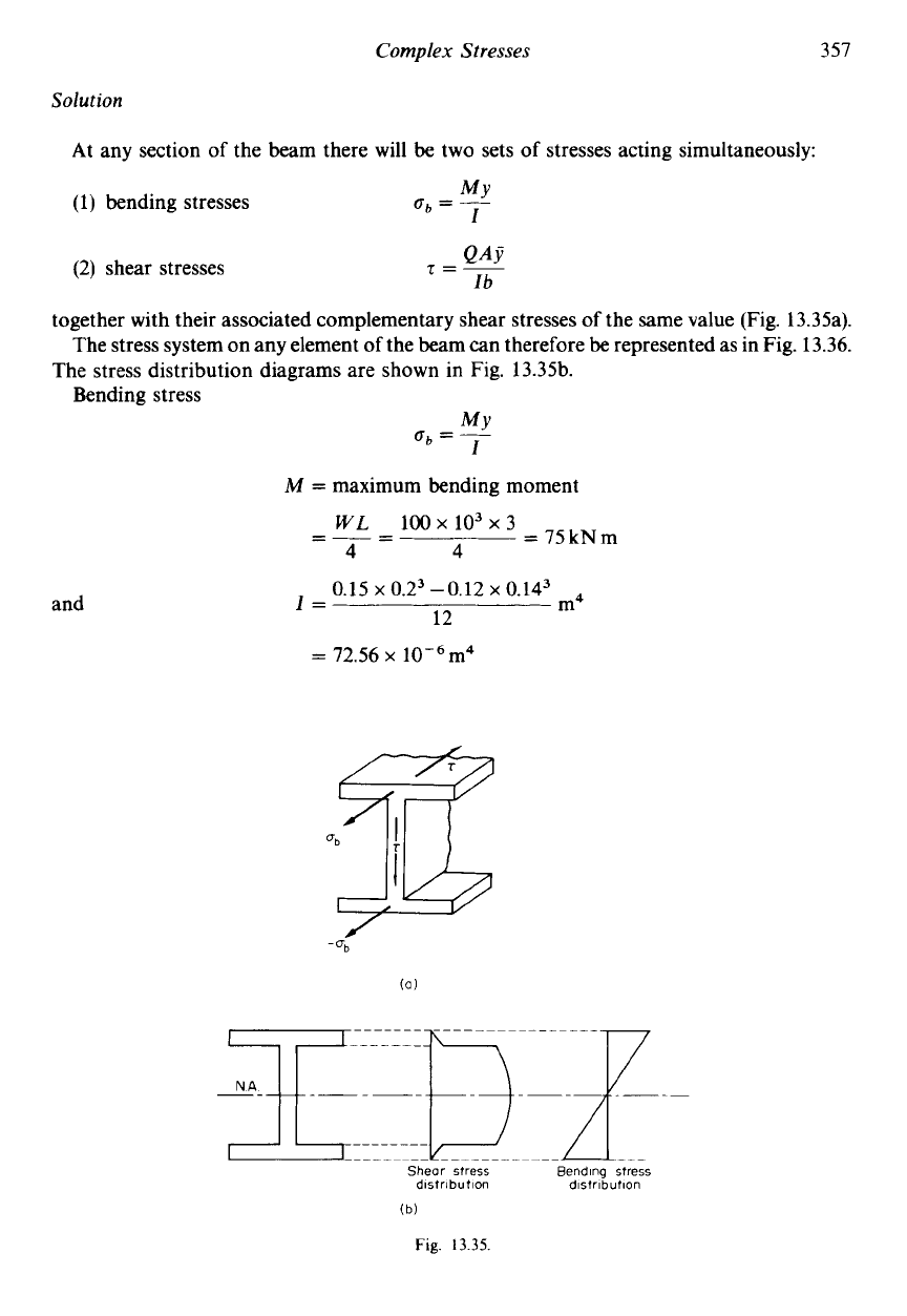
the same value (Fig. 13.35a).
The stress system on any element
of
the beam can therefore
be
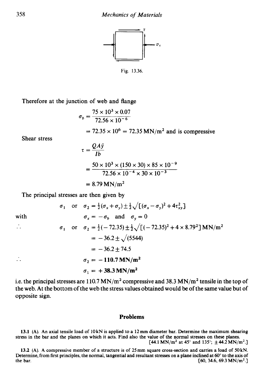
represented as in Fig. 13.36.
The stress distribution diagrams are shown in Fig. 13.35b.
Bending stress
MY
ob
=
~
I
M
=
maximum bending moment
=
75kNm
WL
100~10~x3
=--
-
4
4
and
0.15 x
0.23
-0.12 x 0.143
12
m4
I=
=
72.56 x lOW6m4
Shear stress
Bending stress
distribution
distribution
Fig.
13.35.
358
Mechanics
of
Materials
Fig.
13.36.
Therefore at the junction
of
web and flange
75
x
103
x
0.07
a*
=
72.56
x
=
72.35
x
lo6
=
72.35 MN/m2 and
is
compressive
Shear stress
50
x
lo3
x
(150
x
30)
x
85
x
lo-'
- -
72.56
x
10-4
x
30
x
10-3
=
8.79 MN/m2
The principal stresses are then given by
a1
or
a2
=3(a,+ay)f~J[(.,-.y)2+4t~y]
with
a,
=
-ab
and
ay
=
0
..
a1
or
a2
=
*(-
72.35)+3J[( -72.3q2 +4
x
8.792] MN/m2
=
-
36.2
f
J(5544)
=
-36.2f74.5
..
a2
=
-
110.7
MN/m2
o1
=
+
38.3
MN/m2
i.e. the principal stresses are 110.7 MN/m2 compressive and
38.3
MN/m2 tensile in the top
of
the web. At the bottom of the web the stress values obtained would
be
of the same value but of
opposite sign.
Problems
13.1
(A). An axial tensile load
of
10
kN
is applied to a 12 mm diameter
bar.
Determine the maximum
shearing
C44.1 MN/m2 at
45"
and 135";
k
44.2 MN/m2.]
13.2
(A).
A
compressive member
of
a
structure is
of
25mm square cross-section and carries a load
of
50
kN.
Determine, from first principles, the normal, tangential and resultant stresses on
a
plane inclined at 60" to the axis
of
the bar.
[60,
34.6,
69.3
MN/m2.]
stress in the bar and the planes on which it acts. Find also the value of the normal stresses
on
these planes.
Complex
Stresses
359
13.3
(A). A rectangular block of material is subjected to a shear stress
of
30 MN/m2 together with its associated
complementary shear stress. Determine the magnitude of the stresses
on
a
plane inclined at 30" to the directions of
the applied stresses, which may
be
taken as horizontal.
C26, 15 MN/m2.]
13.4 (A). A material is subjected to two mutually perpendicular stresses, one
60
MN/m2 compressive and the
other 45 MN/m2 tensile. Determine the direct, shear and resultant stresses
on
a
plane inclined at
60"
to the plane
on
which the 45 MN/m2 stress acts.
C18.75, 45.5, 49.2 MN/m2.]
13.5
(A/B). The material of Problem 13.4 is now subjected to an additional shearing stress of 10MN/m2.
Determine the principal stresses acting
on
the material and the maximum shear stress.
[46,
-
61, 53.5 MN/m2.]
13.6 (A/B). At
a
certain section in a material under stress, direct stresses of 45 MN/m2 tensile and 75 MN/m2
tensile act
on
perpendicular planes together with a shear stress
T
acting
on
these planes. If the maximum stress in the
material is limited to 150MN/mZ tensile determine the value of
T.
C88.7 MN/m2.]
13.7 (A/B). At a point in
a
material under stress there is a compressive stress of 200 MN/m2 and a shear stress
of
300
MN/m2 acting
on
the same plane. Determine the principal stresses and the directions of the planes
on
which they
act.
[216MN/mZ at 54.2" to 200MN/m2 plane; -416MN/mZ at 144.2O.I
13.8
(A/B). Atacertain point inamaterial thefol1owingstressesact:a tensilestressof 150 MN/mZ,acompressive
stress of 105 MN/m2 at right angles to the tensile stress and a shear stress clockwise in effect of 30 MN/m2. Calculate
the principal stresses and the directions
of
the principal planes.
C153.5,
-
108.5MN/m2; at 6.7" and 96.7" counterclockwise to 150MN/m2 plane.]
13.9 (B). The stresses across two mutually perpendicular planes at a point in an elastic
body
are 120 MN/m2
tensile with 45 MN/m2 clockwise shear, and 30 MN/m2 tensile with 45 MN/m2 counterclockwise shear. Find (i) the
principal stresses, (ii) the maximum shear stress, and (iii) the normal and tangential stresses
on
a plane measured at
20" counterclockwise to the plane
on
which the 30 MN/m2 stress acts. Draw sketches showing the positions of the
stresses found above and the planes
on
which they act relative to the original stresses.
C138.6, 11.4, 63.6, 69.5, -63.4MN/m2.]
13.10 (B). At a point in a strained material the stresses acting
on
planes at right angles to each other are
200 MN/m2 tensile and
80
MN/m2 compressive, together with associated shear stresses whch may be assumed
clockwise in effect
on
the
80
MN/m2 planes. If the principal stress is limited
to
320 MN/m2 tensile, calculate:
(a) the magnitude of the shear stresses;
(b)
the directions
of
the principal planes;
(c) the other principal stress;
(d) the maximum shear stress.
[219 MN/m2, 28.7 and 118.7" counterclockwise to 200 MN/m2 plane;
-
200MN/m2; 260 MN/m2.]
13.11
(B).
A
solid shaft
of
125 mm diameter transmits 0.5 MW at 300rev/min. It is
also
subjected to
a
bending
moment of 9 kN m and to
a
tensile end load. If the maximum principal stress is limited to 75 MN/m2, determine the
permissible end thrust. Determine the position of the plane on which the principal stress acts, and draw a diagram
showing the position of the plane relative to the torque and the plane of the bending moment.
[61.4kN 61" to shaft axis.]
13.12 (B). At a certain point in a piece of material there are two planes at right angles to one another
on
whch
there are shearing stresses of 150 MN/m2 together with normal stresses of 300 MN/m2 tensile
on
one plane and
150 MN/m2 tensile
on
the other plane. If the shear stress
on
the 150 MN/m2 planes is taken as clockwise in effect
determine for the given point:
(a) the magnitudes of the principal stresses;
(b)
the inclinations of the principal planes;
(c) the maximum shear stress and the inclinations of the planes
on
which it acts;
(d) the maximum strain if
E
=
208 GN/m2 and Poisson's ratio
=
0.29.
C392.7, 57.3 MN/m2; 31.7". 121.7"; 167.7 MN/m2, 76.7", 166.7'; 1810p.1
13.13
(B). A 250mm diameter solid shaft drives a screw propeller with an output of 7 MW. When the forward
speed
of
the vessel is 35 km/h the speed of revolution of the propeller is 240rev/min. Find the maximum stress
resulting from the torque and the axial compressive stress resulting from the thrust
in
the shaft; hence find for a point
on
the surface of the shaft (a) the principal stresses, and
(b)
the directions of the principal planes relative to the shaft
axis. Make a diagram to show clearly the direction of the principal planes and stresses relative to the shaft axis.
[U.L.]
C90.8,
14.7, 98.4, -83.7MN/m2; 47" and 137".]
13.14 (B).
A
hollow shaft
is
460mm inside diameter and 25 mm thick. It is subjected to an internal pressure of
2 MN/m2, a bending moment of 25 kN m and a torque of 40 kN m. Assuming the shaft may
be
treated as a thin
cylinder, make a neat sketch of an element of the shaft, showing the stresses resulting from all three actions.
Determine the values
of
the principal stresses and the maximum shear stress. C21.5, 11.8, 16.6 MN/m2.]
360
Mechanics
of
Materials
13.15
(B).
In a piece
of
material a tensile stress
ul
and a shearing stress 7 act on a given plane. Show that the
principal stresses are always of opposite sign.
If
an additional tensile stress
u2
acts on a plane perpendicular to that
of
13.16
(B).
A
shaft
l00mm
diameter is subjected to a twisting moment
of
7kNm, together with a bending
C47.3,
-
26.9 MN/m2; 37.1 MN/mZ.]
13.17
(B).
A
material is subjected to a horizontal tensile stress of 90MN/mZ and a vertical tensile stress of
120
MN/mZ, together with shear stresses of 75 MN/m2, those on the 120 MN/mZ planes being counterclockwise in
effect. Determine:
ul
,
find the condition that both principal stresses may be
of
the same sign.
CU.L.1
[T
=
J(.l%).I
moment of
2
kN m. Find, at the surface of the shaft, (a) the principal stresses, (b) the maximum shear stress.
(a) the principal stresses;
(b) the maximum shear stress;
(c) the shear stress which, acting alone, would produce the same principal stress;
(d) the tensile stress which, acting alone, would produce the same maximum shear stress.
C181.5,
28.5 MN/mZ; 76.5 MN/m2;
181.5
MN/m2;
153
MN/mZ.]
13.18
(B).
Two planes
AB
and
BC
in an elastic material under load are inclined at 45"
to
each other. The loading
On
AB,
150
MN/mZ direct stress and
120
MN/m2 shear.
On
BC,
80
MN/m2 shear and a direct stress
u.
on the material is such that the stresses on these planes are
as
follows:
Determine the value of the unknown stress
u
on
BC
and hence determine the principal stresses which exist in the
material.
[lW, 214,
-
74 MN/mZ.]
13.19
(B).
A
beam
of I-section,
500
mm
deep and
200
mm
wide, has flanges
25
mm
thck and web 12
mm
thick. It
carries a concentrated load
of
300 kN at the Centre of a simply supported span of 3
m.
Calculate the principal stresses
set up in the
beam
at the point where the web meets the flange.
C83.4,
-
6.15 MN/mZ.]
13.20
(B).
At a certain point on the outside of a shaft which is subjected to a torque and a bending moment the
shear stresses are
100
MN/m2 and the longitudinal direct stress is
60
MN/m2 tensile. Find, by calculation
from
first
principles or by graphical construction which must be justified:
(a) the maximum and minimum principal stresses;
(b) the maximum shear stress;
(c) the inclination of the principal stresses to the original stresses.
Summarize the answers clearly
on
a diagram, showing their relative positions to the original stresses.
[E.M.E.U.] C134.4, -74.4MN/mZ; 104.4MN/m2; 35.5".]
13.21
(B).
A
short vertical column is firmly fixed at the base and projects a distance of 300mm
from
the base. The
column is of I-section,
200mm
deep by l00mm wide, tlanges lOmm thick, web 6mm thick.
An inclined load of
80
kN acts on the top
of
the column in the centre of the section and in the plane containing the
central line
of
the web; the line of action is inclined at 30 degrees to the vertical. Determine the position and
magnitude of the greatest principal stress at the base of the column.
[U.L.] [48 MN/m2 at junction of web and flange.]
CHAPTER
14
COMPLEX STRAIN
AND
THE ELASTIC CONSTANTS
Summary
The
relationships between the elastic constants
are
E
=
2G(1
+v)
and
E
=
3K(1-2v)
Poisson's ratio
v
being defined as the ratio of lateral strain to longitudinal strain and bulk
modulus
K
as the ratio of volumetric stress to volumetric strain.
The
strain in the
x
direction
in a material subjected to three mutually perpendicular stresses
in the
x,
y
and
z
directions is given by
Qx
0
0,
1
&
=--v-L,-v-=-((a
-VQ -VQ)
"E
E
EE"
"
Similar equations apply for
E,
and
E,.
since
Thus the
principal strain
in a given direction can
be
found in terms of the principal stresses,
For a
two-dimensional
stress system (i.e.
u3
=
0),
principal stresses
can
be
found from known
principal strains, since
E
(-52
+
VEl)
(1
-
v2)
E
and o2
=
(81
+
YE21
(1
-
v2)
61
=
When the linear strains in two perpendicular directions are known, together with the
associated shear strain, or when three linear strains are known, the principal strains are easily
determined
by
the use of
Mohr's strain circle.
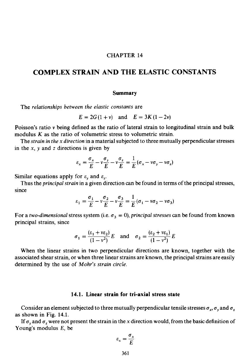
14.1. Linear strain for tri-axial stress state
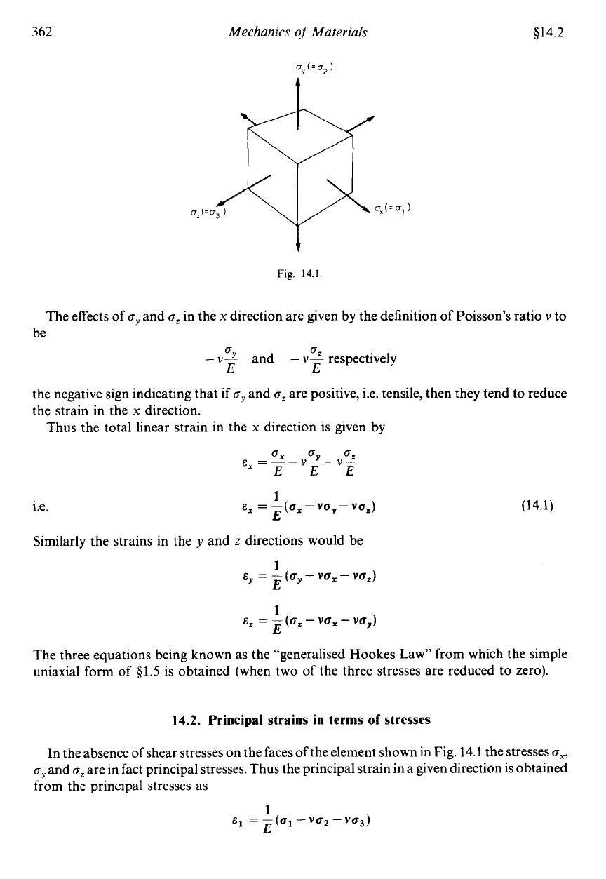
Consider an element subjected to three mutually perpendicular tensile stresses
Q,,
Q,
and
Q,
If
Q,
and
Q,
were not present the strain in the
x
direction would, from the basic definition
of
as shown in Fig. 14.1.
Young's modulus
E,
be
QX
E,
=
-
E
36
1
362
Mechankr
oj
Materials
g14.2
t
Fig.
14.1
The effects of
Q,
and
cZ
in the
x
direction are given by the definition of Poisson’s ratio
v
to
be
Q
0
-
v2
and
-
vP
respectively
E
E
the negative sign indicating that if
Q,
and
Q,
are positive, i.e. tensile, then they tend
to
reduce
the strain in the
x
direction.
Thus the total linear strain in the
x
direction is given by
E,
=
-((6,-VfJy-V~,)
1
E
Le.
(14.1)
Similarly the strains in the
y
and
z
directions would be
1
E
E,
=
-
(Qy
-
vox
-
va,)
E,
=
-(a,
1
-
vox
-
YOy)
E
The three equations being known as the “generalised Hookes Law” from which the simple
uniaxial form of $1.5 is obtained (when two of the three stresses are reduced to zero).
14.2.
Principal strains in
terms
of
stresses
In the absence of shear stresses on the faces of the element shown in Fig. 14.1 the stresses
ox,
CJ)
and
Q,
are in fact principal stresses. Thus the principal strain in a given direction is obtained
from the principal stresses as
1
E
E1
=
-
(ul
-
vu2
-
vu3)
