Hearn E.J. Mechanics of Materials. Volume 1
Подождите немного. Документ загружается.

$1
3.6
Complex Stresses
333
I
I
01
1
v
I
c
I
Fig.
13.9.
Mohr’s
stress
circle.
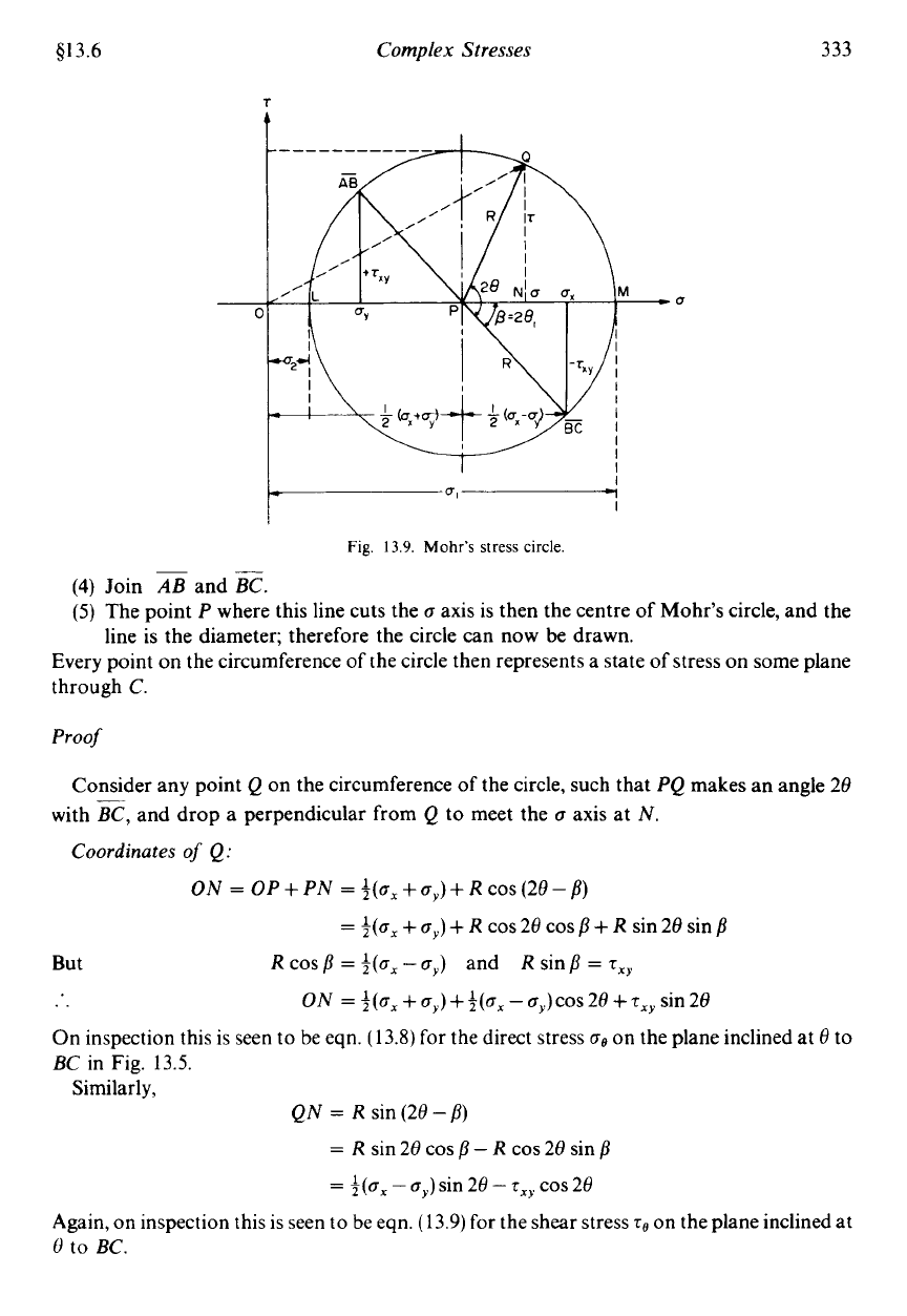
Join
AB
and
z.
The point
P
where this line cuts the
a
axis is then the centre of Mohr’s
line is the diameter; therefore the circle can now
be
drawn.
circle,
and the
Every point on the circumference of the circle then represents a state of stress on some plane
through
C.
Proof
Consider any point
Q
on the circumference of the circle, such that
PQ
makes an angle 28
with
E,
and drop a perpendicular from
Q
to
meet the
a
axis at
N.
Coordinates
of
Q:
ON
=
OP+PN
=
~(0,+a,)+R~0~(28-fl)
=
$(ax
+
a,)
+
R
cos 28 cos
p
+
R sin 28 sin
p
But R cos
p
=
+(a,
-
a,)
and
R
sin
p
=
T,~
..
On
inspection this
is
seen
to
be eqn.
(13.8)
for the direct stress
BC
in Fig. 13.5.
ON
=
+(ax
+
a,) ++(a,
-
a,)cos 28
+
T,,
sin
28
on the plane inclined at
8
to
Similarly,
QN
=
R
sin (28
-
p)
=
Rsin28cos~-Rcos28sin~
=
+(ax
-
a,)
sin 28
-
T,~
cos 28
Again, on inspection this is seen
to
be eqn. (13.9) for the shear stress
TO
on the plane inclined at
t)
to
BC.
334
Mechanics
of
Materials
613.7
Thus the coordinates
of
Q
are the normal and shear stresses on
a
plane inclined at
8
to
BC
in the original stress system.
N.B.-Single angle
ZPQ
is
28
on Mohr’s circle and not
8,
it is evident that
angles are
doubled on Mohr’s circle.
This is the only difference, however, as they are measured in the
same direction and from the same plane in both figures (in this case counterclockwise from
BC
).
-
Further points to note are:
(1)
The direct stress is a maximum when
Q
is at
M,
i.e.
OM
is the length representing the
maximum principal stress
a1
and
28,
gives the angle of the plane
8,
from
BC.
Similarly,
OL
is the other principal stress.
(2)
The maximum shear stress is given by the highest point on the circle and is represented
by the radius of the circle. This follows since shear stresses and complementary shear
stresses have the same value;
therefore the centre
of
the circle will always lie on the
a
axis
midway between
a,
and
a,.
(3)
From the above point the direct stress on the plane of maximum shear must
be
midway
between
a,
and
a,,,
i.e.
$(a,
+
a,).
(4)
The shear stress on the principal planes is zero.
(5)
Since the resultant of two stresses at
90”
can
be
found from the parallelogram of vectors
as the diagonal, as shown in Fig.
13.10,
the resultant stress on the plane at
8
to
BC
is
given by
OQ
on Mohr’s circle.
Fig.
13.10.
Resultant stress
(8,)
on
any
plane.
The graphical method of solution of complex stress problems using Mohr’s circle is
a
very
powerful technique since all the information relating to any plane within the stressed element
is
contained in the single construction. It thus provides
a
convenient and rapid means of
solution which is less prone to arithmetical errors and is highly recommended.
With the growing availability and power of programmable calculators and microcom-
puters it may be that the practical use of Mohr’s circle for the analytical determination
of
stress (and strain-see Chapter
14)
values will become limited. It will remain, however, a
highly effective medium for the teaching and understanding of complex stress systems.
A
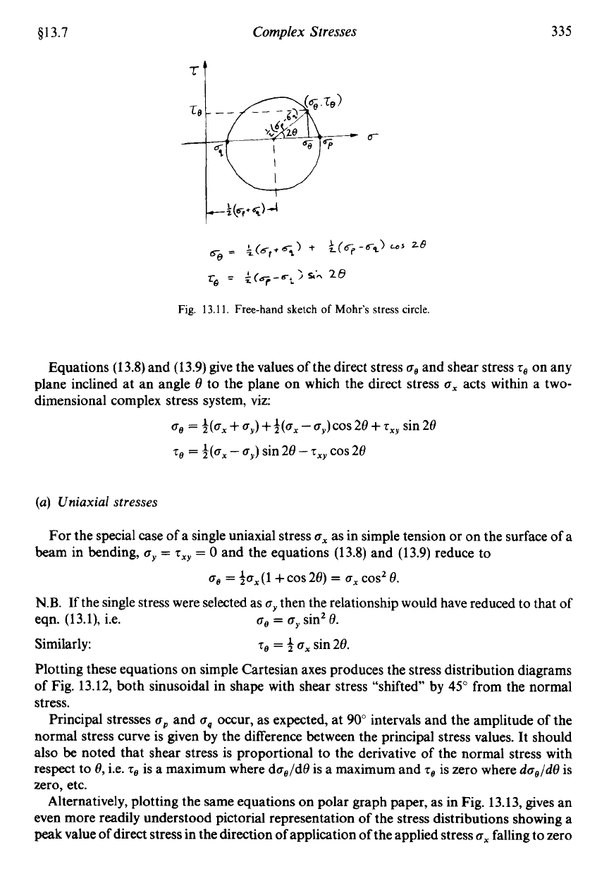
free-hand sketch
of
the Mohr circle construction, for example, provides a convenient
mechanism for the derivation (by simple geometric relationships) of the principal stress
equations
(13.1 1)
or
of
the equations for the shear and normal stresses on any inclined plane
in terms
of
the principal stresses as shown in Fig.
13.11.
13.7.
Alternative representations
of
stress distributions at a point
The way in which the stress at a point vanes with the angle at which a plane is taken through
the point may be better understood with the aid of the following alternative graphical
representations.
$13.7
Complex
Stresses
tt
335
'6
Fig.
13.11.
Free-hand
sketch
of
Mohr's
stress
circle.
Equations
(13.8)
and
(13.9)
give the values of the direct stress
ug
and shear stress
re
on any
plane inclined at an angle
8
to the plane on which the direct stress
u,
acts within a two-
dimensional complex stress system, viz:
ug
=
*(a,
+
a,)
+3(ux
-
0,)
cos
28
+
s,,
sin
28
q,
=
i(u,
-
cy)
sin
28
-
T~~
cos
28
(a)
Uniaxial
stresses
For the special case of a single uniaxial stress
ux
as in simple tension or on the surface of a
beam in bending,
u,
=
zxy
=
0
and the equations
(13.8)
and
(13.9)
reduce to
00
=
$0,
(1
+
COS
28)
=
6,
COS'
8.
N.B.
If the single stress were selected as
u,
then the relationship would have reduced
to
that of
eqn.
(13.1),
i.e.
ae
=
uy
sin'
8.
Similarly:
70
=
3
ox
sin
28.
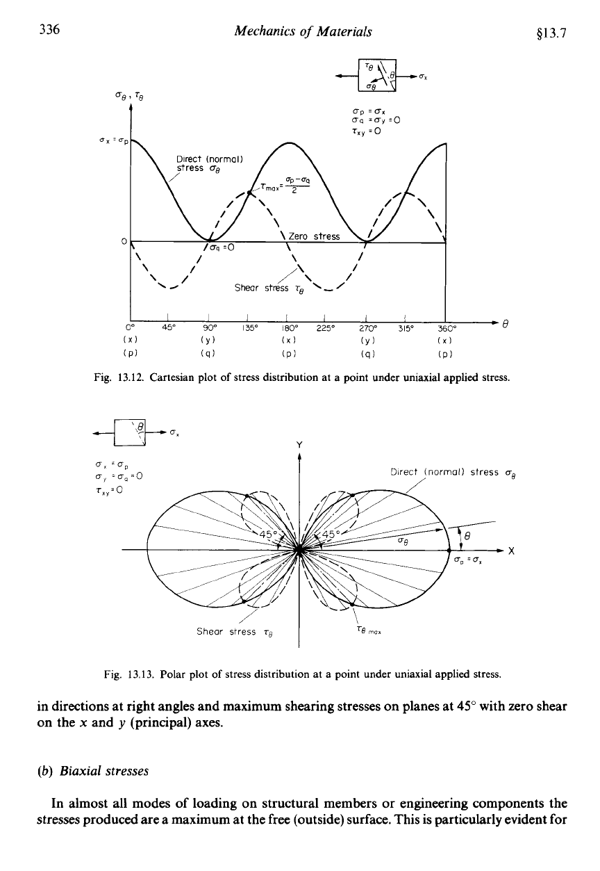
Plotting these equations on simple Cartesian axes produces the stress distribution diagrams
of Fig.
13.12,
both sinusoidal in shape with shear stress "shifted by
45"
from the normal
stress.
Principal stresses
op
and
oq
occur, as expected, at
90"
intervals and the amplitude
of
the
normal stress curve is given by the difference between the principal stress values. It should
also be noted that shear stress is proportional to the derivative of the normal stress with
respect to
8,
i.e.
70
is a maximum where doe/d8 is a maximum and
70
is zero where
da,/d8
is
zero, etc.
Alternatively, plotting the same equations on polar graph paper, as in Fig.
13.13,
gives an
even more readily understood pictorial representation of the stress distributions showing a
peak
value of direct stress in the direction of application of the applied stress
ox
falling to zero
336
Mechanics
of
Materials
$13.7
re
I
up
=ux
uq
=uy
=o
r,,
:O
1 1 1
I
1
I
I
O0
45"
90"
135'
180"
225'
270"
315'
?
3"8
IX)
(Y)
(X)
(Y)
(X)
(P)
(q)
(P)
(q)
(PI
Fig. 13.12. Cartesian plot
of
stress distribution at a point under uniaxial applied stress.
Y
Direct
(normal)
stress
us
/
X
Shear
stress
ro
Fig.
13.13.
Polar plot
of
stress distribution at a point under uniaxial applied stress.
in directions at right angles and maximum shearing stresses on planes at
45"
with zero shear
on the
x
and
y
(principal) axes.
(b)
Biaxial stresses
In almost all modes of loading on structural members
or
engineering components the
stresses produced are a maximum at the free (outside) surface. This is particularly evident for
$13.7
Complex
Stresses
337
the cases of pure bending or torsion as shown by the stress diagrams of Figs.
4.4
and
8.4,
respectively, but is also true for other more complex combined loading situations with the
major exception of direct bearing loads where maximum stress conditions can be sub-surface.
Additionally, at free surfaces the stress normal to the surface is always zero
so
that the most
severe stress condition often reduces, at worst, to a two-dimensional plane stress system
within the surface
of
the component. It should be evident, therefore that the biaxial stress
system is of considerable importance to practical design considerations.
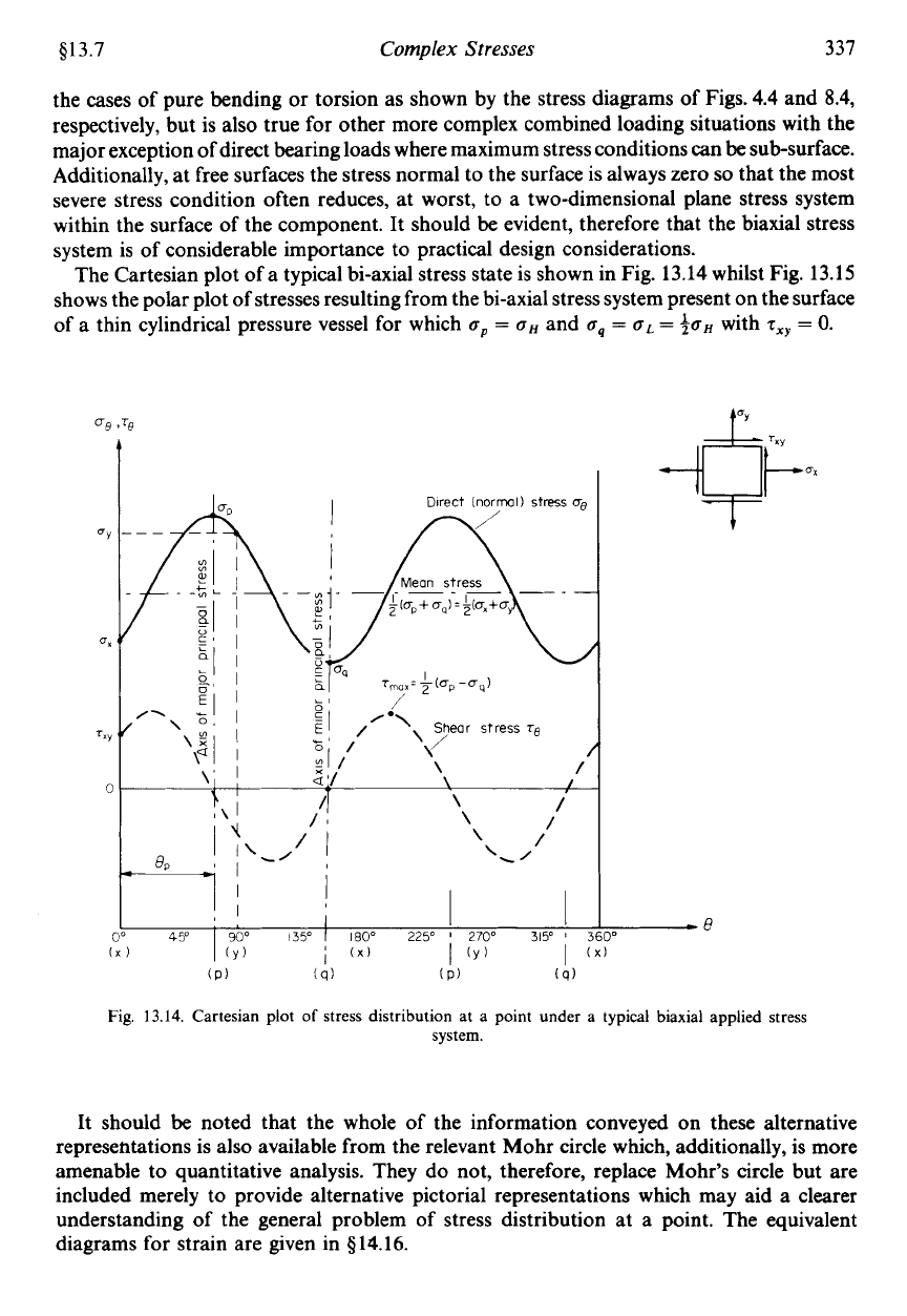
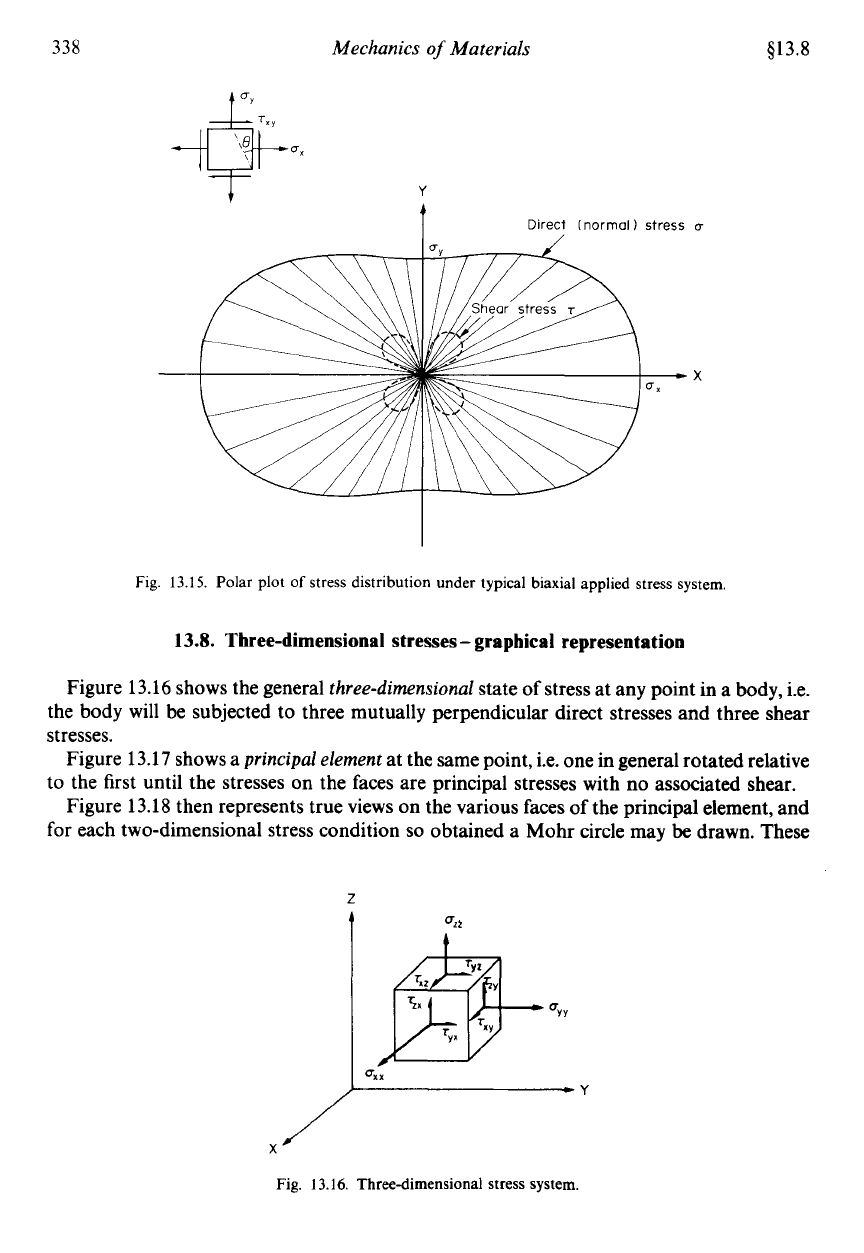
The Cartesian plot of a typical bi-axial stress state is shown in Fig.
13.14
whilst Fig.
13.15
shows the polar plot of stresses resulting from the bi-axial stress system present on the surface
of a thin cylindrical pressure vessel for which
oP
=
oH
and
oq
=
uL
=
3oH
with
t,,,
=
0.
Fig.
13.14.
Cartesian plot
of
stress distribution at a point under a typical biaxial applied stress
system.
It should be noted that the whole of the information conveyed on these alternative
representations is also available from the relevant Mohr circle which, additionally, is more
amenable to quantitative analysis. They do not, therefore, replace Mohr’s circle but are
included merely to provide alternative pictorial representations which may aid a clearer
understanding of the general problem of stress distribution at a point. The equivalent
diagrams for strain are given in
914.16.
338
Mechanics
of
Materials
Y
t
Direct
lnormol)
stress
u
813.8
Fig.
13.15.
Polar plot
of
stress distribution under typical biaxial applied stress system.
13.8.
Three-dimensional stresses
-
graphical
representation
Figure 13.16 shows the general
three-dimensional
state of stress at any point in a body, i.e.
the body will be subjected to three mutually perpendicular direct stresses and three shear
stresses.
Figure 13.17 shows a
principal element
at the same point, i.e. one in general rotated relative
to the first until the stresses
on
the faces are principal stresses with no associated shear.
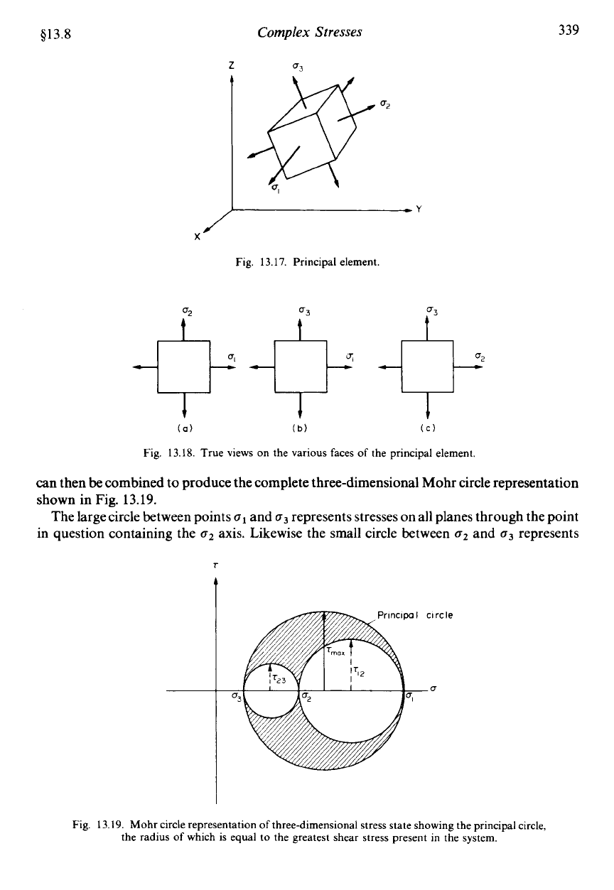
Figure 13.18 then represents true views on the various faces of the principal element, and
for each two-dimensional stress condition
so
obtained a Mohr circle may
be
drawn. These
F
QYY
Fig. 13.16. Three-dimensional
stress
system.
$13.8
Complex
Stresses
339
Fig. 13.17. Principal element.
Q3
Q-
(a)
(b)
(C)
Fig. 13.18. True views on the various faces of the principal element
can then
be
combined
to
produce the complete three-dimensional Mohr circle representation
shown in Fig.
13.19.
The largecircle between points
u1
and
o3
represents stresses on all planes through the point
in question containing the
o2
axis. Likewise the small circle between
o2
and
u3
represents
Fig. 13.19. Mohr circle representation of three-dimensional stress state showing the principal circle,
the radius
of
which is equal
to
the greatest shear stress present in the system.
340
Mechanics
of
Materials
$13.8
stresses on all planes containing the
o1
axis and the circle between
o1
and
o2
all planes
containing the
o3
axis.
There are, of course, an infinite number of planes passing through the point which do not
contain any of the three principal axes, but it can be shown that all such planes are repre-
sented by the shaded area between the circles. The procedure involved in the location of a
particular point in the shaded area which corresponds to any given plane is covered in
Mechanics ojMaterials
2.t
In practice, however, it is often the maximum direct and shear
stresses which will govern the elastic failure of materials. These are determined from the
larger of the three circles which is thus termed the
principal circle
(T,,.,~~
=
radius).
It is perhaps evident now that in many two-dimensional cases the maximum (greatest) shear
stress value will be missed by not considering
o3
=
0
and constructing the principal circle.
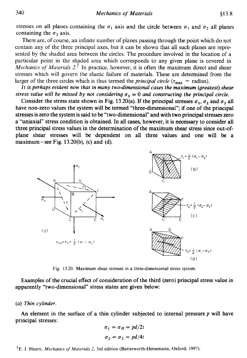
Consider the stress state shown in Fig. 13.20(a).
If
the principal stresses
ol,
o2
and
o3
all
have non-zero values the system will
be
termed “three-dimensional”; if one of the principal
stresses is zero the system is said to
be
“two-dimensional” and with two principal stresses zero
a “uniaxial” stress condition is obtained. In all
cases,
however, it is necessary to consider all
three principal stress values in the determination of the maximum shear stress since out-of-
plane shear stresses will be dependent on all three values and one will
be
a
maximum
-
see Fig. 13.20(b), (c) and (d).
1”
Fig.
13.20.
Maximum shear
stresses
in
a
three-dimensional
stress
system.
Examples
of
the crucial effect of consideration
of
the third (zero) principal stress value in
apparently “two-dimensional” stress states are given below:
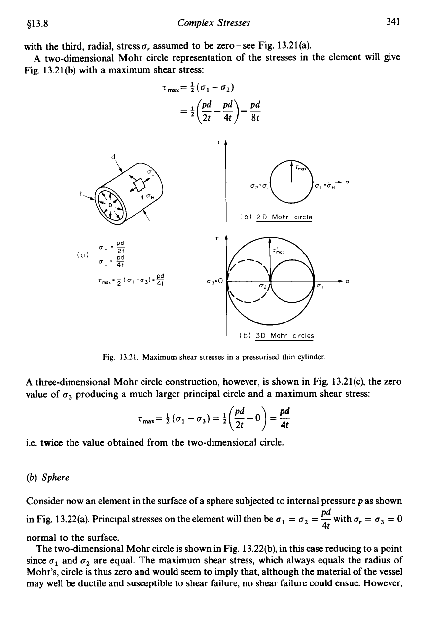
(a) Thin cylinder.
principal stresses:
An element in the surface of a thin cylinder subjected to internal pressurep will have
o1
=
OH
=
pd/2t
o2
=
aL
=
pd/4t
$E.
J.
Hearn,
Mechanics
of
Materials
2, 3rd
edition (Butterworth-Heinemann, Oxford,
1997).
413.8
Complex Stresses
34
1
with the third, radial, stress
o,
assumed to
be
zero-see Fig. 13.21(a).
Fig. 13.21(b) with
a
maximum shear stress:
A
two-dimensional Mohr circle representation of the stresses in the element will give
1
Tmax=T(o1-0~)
I
(b)
3D
Mohr
circles
Fig.
13.21.
Maximum
shear stresses
in
a
pressurised
thin cylinder
A
three-dimensional Mohr circle construction, however, is shown in Fig. 13.21(c), the zero
value of
o3
producing a much larger principal circle and a maximum shear stress:
Tmax=+(ol-uj)=$
--0
=-
(E
)
:
i.e.
twice
the value obtained from the two-dimensional circle.
(b)
Sphere
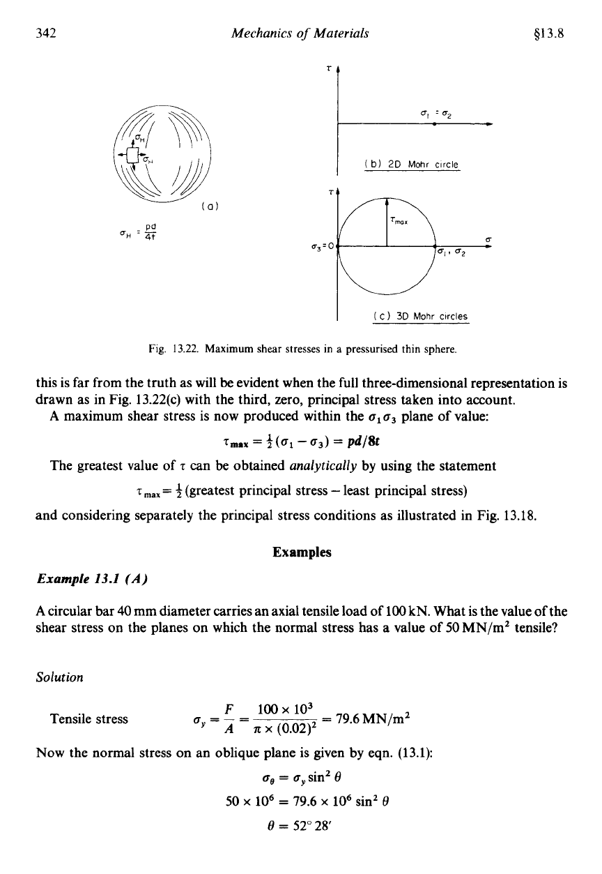
Consider now an element in the surface of a sphere subjected to internal pressure pas shown
in Fig. 13.22(a). Principal stresses on the element will then
be
o1
=
o2
=
-
with
or
=
o3
=
0
pd
4t
normal to the surface.
The two-dimensional Mohr circle is shown in Fig. 13.22(b), in this case reducing to a point
since
o1
and
u2
are equal. The maximum shear stress, which always equals the radius of
Mohr's, circle is thus zero and would seem to imply that, although the material of the vessel
may well
be
ductile and susceptible to shear failure, no shear failure could ensue. However,
342
Mechanics
of
Materials
$13.8
‘t
I
(
b)
2D
Mohr
circle
TI
.
Pd
UH
-
-
4t
I
(
C)
30
Mohr
circles
Fig.
13.22.
Maximum shear stresses in a
pressurised
thin
sphere.
this is far from the truth as will
be
evident when the full three-dimensional representation is
drawn as in Fig. 13.22(c) with the third, zero, principal stress taken into account.
A
maximum shear stress is now produced within the
olo3
plane
of
value:
T,,,
=
3
(01
-
03)
=
pd/8t
The greatest value
of
z
can be obtained
analytically
by using the statement
z
max
=
3
(greatest principal stress
-
least principal stress)
and considering separately the principal stress conditions as illustrated in Fig. 13.18.
Examples
Example
13.1
(A)
A
circular bar
40
mm diameter carries an axial tensile load of 100 kN. What is the value of the
shear stress on the planes on which the normal stress has
a
value of
50
MN/m’ tensile?
So
1
ut
ion
Tensile stress
=
79.6 MN/mZ
F
100
x
103
A
It
x
(0.02)’
=-=
Now
the normal stress on an oblique plane is given by eqn. (13.1):
og
=
o,
sin’
8
50
x
lo6
=
79.6
x
lo6
sin’
6
8
=
52”
28’
