Hawkes P.W., Spence J.C.H. (Eds.) Science of Microscopy. V.1 and 2
Подождите немного. Документ загружается.

Chapter 8 LEEM and SPLEEM 615
a magnetic stigmator (6). The primary image in the center of the beam
separator is imaged with a magnetic intermediate lens (9) and a pro-
jective lens (10) onto the fi nal screen, and the diffraction pattern by
adjusting the focal length of the intermediate lens. The purpose of the
electrostatic fi lter lens (11) was to fi lter out secondary and inelastically
scattered electrons but was later removed because it was found that the
dispersive properties of the magnetic beam separator (1) were suffi cient
to eliminate them from the image. A pair of multichannel plates (12)
enhances the image intensity on the fl uorescent screen (8), allowing
observation and image recording with a video camera (13) at very low
beam currents. Both illumination and imaging columns are equipped
with defl ectors and stigmators, some of which are indicated (16). Emis-
sion microscopy is possible with thermionic emission by heating the
specimen, with photoelectrons generated by a 100-W high-pressure Hg
arc lamp (14) and with secondary electrons using an auxiliary electron
gun (15).
While Figure 8–9 shows the principle of the LEEM system, more
recent instruments differ considerably in detail. For example, a transfer
lens, which transfers the diffraction pattern from the back focal plane
of the objective lens toward the front of the intermediate lens, is now
inserted just behind the beam separator, so that the illuminating beam
does not have to pass through the contrast aperture as in the original
design. The electrostatic triode lens is now replaced by lenses with
better resolution such as the electrostatic tetrode lens, the magnetic
diode lens, or the magnetic triode lens, which will be briefl y discussed
below. The beam separator has been improved in a variety of ways,
such as by close-packed or separated multiple magnetic prisms, con-
centric square or round pole pieces, or a Wien fi lter, resulting in defl ec-
tion angles ranging from 16° to 90° compared to the original 60°. In
addition, energy fi lters have been added to instruments so that they
can also be used for AEEM, low electron energy loss microscopy
(LEELM), energy-fi ltered SEEM, and spectroscopic PEEM.
Before discussing these components of an LEEM instrument, a short
account of the various designs is appropriate. The fi rst major develop-
ment after the original instrument and a similar one
43
also used a beam
separator with 60° defl ection but with close-packed multiple magnetic
prisms and only magnetic lenses, including the objective lens, a LaB
6
cathode, and a transfer lens so that the contrast aperture could be
placed behind the beam separator.
44
The magnetic prism on the
illumination side of the instrument can be excited differently from that
on the exit side so that a higher beam energy is possible than on the
imaging side, which allows AEEM when an energy fi lter is added to
the instrument. The dense packing of the magnetic lenses together
with the shielding of the beam separator and the specimen region
makes the magnetic shielding used in the more open earlier instru-
ments unnecessary. The addition of an energy fi lter allows not only
AEEM but in combination with synchrotron radiation also spectro-
scopic X-ray PEEM.
13,45,46
From this instrument the presently most wide-
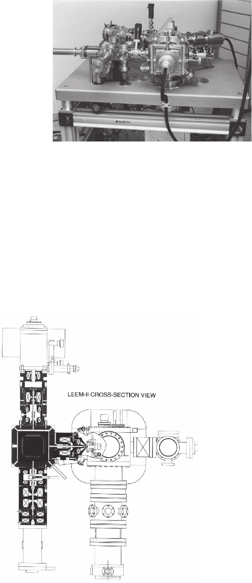
spread commercial instrument shown in Figure 8–10 developed later.
The version with energy fi lter, the SPELEEM, which is presently the
616 E. Bauer
most versatile instrument, has been described repeatedly
47
in connec-
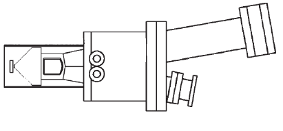
tion with PEEM. Therefore, a cross section of the presently best home-
built pure LEEM instrument (Figure 8–11)
48
is shown here. Similar to
the previous instrument (Figure 8–10) it has densely packed magnetic
lenses both in the illumination (top) and in the imaging (bottom)
section. However, it uses a beam separator with 90° defl ection that is
incorporated in the vacuum system (center). The objective lens (right
Figure 8–10. Commercial LEEM instrument. The illumination column is on
the right side and the imaging column on the left side. The 60° beam separator
is hidden behind the specimen chamber in the center, which also contains the
objective lens. (Courtesy of ELMITEC GmbH.)
Figure 8–11. Cross
section of a LEEM
instrument with a 90°
separator. The illumina-
tion column with the
fi eld emission gun is on
top and the imaging
column is at the bottom.
The right side shows the
specimen chamber, air-
lock, and part of the
pumping system.
48
Chapter 8 LEEM and SPLEEM 617
side) is a magnetic diode and consists of two sections with opposing
image rotation. A commercial cold fi eld emission electron gun (top)
with an energy spread of about 0.25 eV allows a theoretical resolution
of 0.4 nm at 10 eV. The right side is the specimen chamber and a prepa-
ration chamber plus airlock. This instrument presently holds the
resolution record (0.5 nm) among the instruments without aberration
correction.
The instruments described above are free-standing instruments.
There has long been the wish to add a LEEM instrument to existing
UHV systems. To be practical, such LEEM systems must be much
smaller and have small defl ection angles. Two solutions were chosen:
one uses a simple beam separator with a small defl ection angle (10°)
49
and the other one uses three defl ections by 45°.
50
In both cases the
instrument is mounted on an 8-in.-diameter UHV fl ange and can be
attached to a UHV system via a 6-in.-diameter UHV fl ange. All lenses
are electrostatic, including the electrostatic tetrode lens. In contrast to
magnetic lenses, electrostatic lenses can be easily fl oated at high voltage.
Therefore the complete electron optics can be at high voltage so that
the specimen can be near ground potential, whereas in the magnetic
lens systems the specimen is at high voltage. Because of the compact
design, high-voltage insulation requirements allow fi nal energies of
only 5 keV, in contrast to the 15–20 keV used in the larger systems. Only
the extraction electrode of the tetrode lens can be increased to 15 kV.
External fi elds are screened by internal µ-metal screening. Figure 8–12
shows the mechanical confi guration of one of these fl ange-on LEEM
instruments.
49
Its overall length is 60 cm and its weight is about 20 kg.
Several other LEEM instrument designs have been proposed and in
part realized. One design
51
included some interesting features such as
a combined magnetic-electrostatic beam separator that allows different
energies to be used in the illumination and imaging beams, an electro-
static tetrode combined with a Schwarzschild-type optical mirror objec-
tive, which focuses UV radiation onto the specimen for PEEM, and a 70°
spherical condenser for electron energy fi ltering. Unfortunately it never
came into operation. In another design that is used in a commercial
instrument
52
the beam separation is achieved by a Wien fi lter into which
the illumination beam enters at an angle of 36° while the imaging beam
runs along its optical axis. A second Wien fi lter is used as an energy
fi lter. This instrument has been used mainly for PEEM, MEM, and
6˝ FLANGE
VACUUM
CHAMBER
APERTURE
MANIPULATOR
FLANGES
BASIS
FLANGE 8˝
ELECTRON
GUN UNIT
IMAGE
INTENSIFIER
UNIT
MAGNETIC
SCREENING
OBJECTIVE
LENS
BEAM
SEPARATOF
SPECIMEN
Figure 8–12. Schematic of the mechanical confi guration of a fl ange-on LEEM
system.
49
618 E. Bauer
metastable impact electron emission microscopy (MIEEM). Apparently
the diffi culty of aligning the incident beam normal to the surface and
keeping the imaging beam on axis makes systematic LEEM studies with
acceptable resolution diffi cult. A similar problem has to be overcome in
an instrument in which the beam separator is replaced by a W single
crystal.
53
This crystal is tilted 45° against the optical axis and refl ects a
low-energy electron beam from a side-mounted gun along the optical
axis. Exact normal incidence on the sample requires that the refl ector is
on the optical axis, which would obstruct the imaging beam. This
instrument, called a double refl ection electron emission microscope
(DREEM), is also commercially available. Other LEEM instruments
have been built as well but their design has not been published.
All instruments discussed up to now suffer from the large chromatic
and spherical aberration of the objective lens. That these aberrations
can be corrected with an electron mirror has been known for some time
but only during the past decade have efforts been made to develop
aberration-corrected instruments. Simultaneously, however, the aber-
rations of the beam separator have to be corrected. This has led to the
design of a complex system
54,55
that has already been realized in the
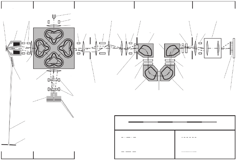
so-called SMART (Spectromicroscope for All Relevant Techniques)
instrument,
17,56,57
schematically shown in Figure 8–13. Similar to the
SPELEEM system, the instrument is designed for a wide range of opera-
tion modes,
58
one of which is LEEM. The centerpiece is the beam separa-
objective beam separator transfer optics energy filter projector / detector
X-ray optics
X-ray
illumination
X-ray
mirror
mirror corrector
axial ray
optic axis
field ray
dispersion ray
0 100 200 300 400 500 600 mm
specimen
objective
lens
electric-magnetic
deflectors
field emission gun
deflector D1
condensor lens
transfer lens T1 field aperture energy selection slit projector lens
dipole P1
quadrupole
T3
D5
H6
H5
H4
P3
P4
P2
H3
H2
dodecapole
L5 T2L3 L4 D4D3D2
beam
separator
aperture
hexapole H1
electric-magnetic
deflectors/dodecapoles
outer
electrodes
tetrode
mirror
monochromator exit slit
inner
electrode
L2
field
lens L1
channel plate
slow scan CCD
Figure 8–13. Schematic of the electron-optical confi guration of the SMART system.
56
Chapter 8 LEEM and SPLEEM 619
tor to which the illumination system, a fi eld emission gun, the objective
lens, and the mirror corrector are attached via fi eld lenses (L). Beyond
the beam separator fi ve electrostatic lenses transfer either the diffrac-
tion pattern in the plane of the contrast aperture between L
3
and L
4
or
the primary image at various magnifi cations into the entrance of the
Ω-type energy fi lter where the fi eld limiting aperture is located. With
the energy selection slit inserted, the subsequent projective lens system
produces an energy fi ltered image or diffraction pattern on the Channel
plate-fl uorescent screen unit, which is fi beroptically coupled to the CCD
camera. Numerous defl ectors (D
i
) allow precise alignment and several
n-pole elements (n = 2, 6, 12) are used for the correction of residual
aberrations. The instrument operates at 15 kV and is expected to have
a resolution in LEEM of 1 nm at 10 eV.
Unless aberrations of the beam separator, the energy fi lter, other optical
components or vibrations, electromagnetic fi elds, charging, or other dis-
turbances are resolution limiting the chromatic and spherical aberra-
tions of the objective lens determine the resolution. The aberrations of the
accelerating fi eld of the cathode lens cause much higher limiting values
of the resolution than in transmission microscopy. These values can be
calculated analytically by assuming that the lens may be separated into
a homogeneous fi eld in front of the specimen, which produces a virtual
image behind the specimen, and an einzel lens, which produces a real
image of the virtual image. Realistic calculations have to consider the
cathode lens as a unit and have been made by many authors. A compari-
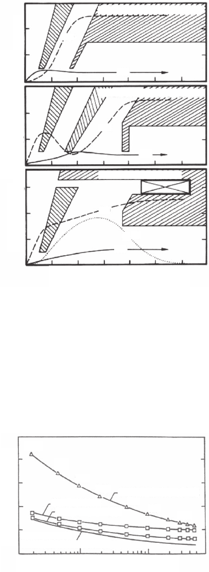
son of the resolution obtainable with an electrostatic triode, electrostatic
tetrode, and magnetic triode lens (Figure 8–14) shows that the electro-
static tetrode and the magnetic triode lenses are much better than the
original triode lens because in the latter the fi eld strength at the sample
is low under focusing conditions (1.18–0.52 kV/mm vs. 10 kV/mm in the
other two lens types) (Figure 8–15).
59
The data are for the optimum aper-
ture, which is determined by minimizing the contributions of the aber-
ration discs due to diffraction at the angle-limiting aperture, chromatic
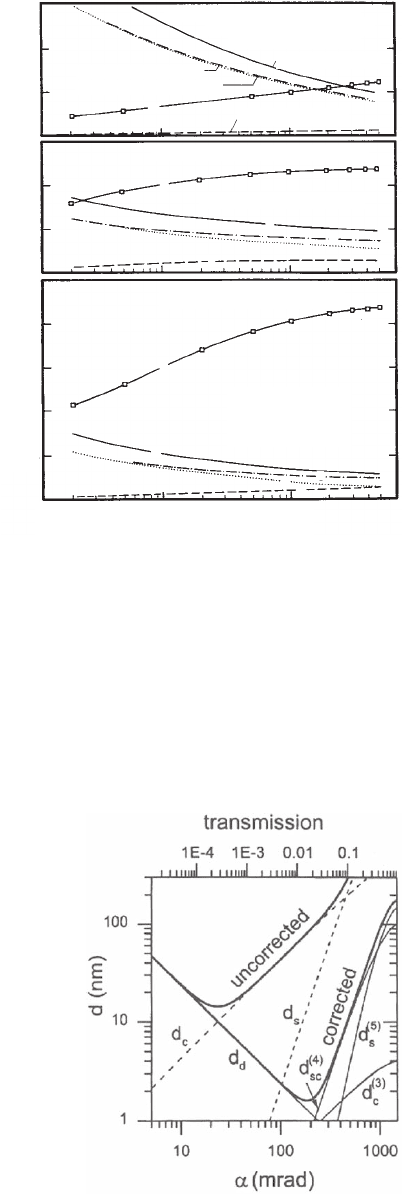
and spherical aberrations. These contributions can be seen in Figure 8–16
together with the radius of the optimum aperture. From these fi gures it
is clear that the magnetic triode is superior to the electrostatic tetrode
both in resolution and transmission. Transmission does not play an
important role in LEEM but is important in XPEEM with photoelectrons
and secondary electrons, which have a wide angular distribution. Today
the magnetic diode, which differs from the triode only in that both pole
shoes are at the same potential, is the standard in the best LEEM instru-
ments without aberration correction while the electrostatic tetrode is the
domain of the smaller, purely electrostatic LEEM instruments. In the
multimethod instruments
15–17,44,56,57
combined electrostatic–magnetic
cathode lenses, such as the magnetic triode, are useful because they
allow the fi eld strength at the specimen to be varied. Such a lens with a
design somewhat different from that shown in Figure 8–14 is used in the
4 Electron Optics
620 E. Bauer
SMART instrument. Because the chromatic and spherical aberrations of
the objective lens are corrected in this instrument by the mirror corrector,
the largest aberrations are now those of the energy fi lter. The resolution
improvement obtained by correction is shown in Figure 8–17 as a func-
tion of angular acceptance for a start energy of 10 eV, an energy width of
b. ELECTROSTATIC TRIODE
c. ELECTROSTATIC TETRODE
d. MAGNETIC TRIODE
TADIAL POSITION (mm)
2
4
2
4
2
24681012
4
6
AXIAL POSITION (mm)
E(Z)
E(Z)
E(Z)
r(Z)
r(Z)
r(Z)
B
Z
(Z)
Figure 8–14. Schematic confi gurations of LEEM cathode lenses. One-half of
the electrodes/pole pieces, the electron energy E(z), and the electron ray path
r(z) is shown.
59
1.18
1.15
1.12
1.08
.98
FOCUSSED E.S. TRIODE
.87
.52
E.S. TETRODE
MAGNETIC TRIODE
HOMOGENEOUS
(NON-FOCUSSING) FIELD
INITIAL ENERGY (eV)
RESOLUTION δ (nm)
1
5
10
15
20
10 100
Figure 8–15. Comparison of the resolution of the lenses shown in Figure 8–14
for a fi nal energy of 20 keV, an energy spread of 0.5 eV, and optimized
aperture.
59
Chapter 8 LEEM and SPLEEM 621
2 eV, and a fi nal energy of 15 keV.
57
The dashed lines show the contribu-
tions of the aberrations of the uncorrected lens and the thin solid lines
those of the energy fi lter. For LEEM instruments with LaB
6
or fi eld emis-
sion guns that have lower energy widths, the resolution is still improved
by about a factor of 5. The main advantage of aberration correction, the
large increase in transmission, however, comes to bear only in emission
microscopy, in particular in AEEM and XPEEM.
b. ELECTROSTATIC TRIODE
c. ELECTROSTATIC TETRODE
d. MAGNETIC TRIODE
FIELD STRENGTH 1.18→ .58 kV/mm
FOR FOCUS AT INFINITY
FIELD STRENGTH 10
kV/mm
FIELD STRENGTH 10 kV/mm
a – NET RESOLUTION
b – DIFFRACTION
c – CHROMATIC
d – SPHERICAL
ϒ – APERTURE RADIUS
NET RESOLUTION δ
0
DIFFRACTION .6 λ
0
/α
opt
CHROMATIC C
CO
α
opt
∆E/E
0
SPHERICAL C
SO
α
opt
3
INITIAL ENERGY (eV)
110100
5
10
5
10
5
10
15
20
RESOLUTION COMPONENT (nm) OR RADIUS (µm)
ϒ
ϒ
ϒ
a
a
b
b
c
c
d
d
Figure 8–16. Energy
dependence of the contri-
butions of the spherical,
chromatic, and diffrac-
tion aberrations (dashed,
dotted, and dash–dotted
lines) to the resolution
(solid line) at the optimum
aperture with radius r
for the lenses shown in
Figure 8–14. In the triode
the fi eld strength has to
be changed for forming a
real image; in the other
two lenses 10 kV/mm has
been choosen. Energy
spread 0.5 eV.
59
Figure 8–17. Resolution limit d as a
function of the acceptance angle α
without and with correction of the
spherical and chromatic aberra-
tions. Data for the system shown in
Figure 8–13 for 10 eV start energy
and 2 eV energy spread. In the
uncorrected system d is limited by
the chromatic and spherical aberra-
tions (dashed lines) and in the cor-
rected system by higher order
aberrations (solid lines).
57
622 E. Bauer
The next critical component of a LEEM instrument is the beam sepa-
rator. Early beam separators
3,43
aimed only at the reduction of the uni-
directional beam dispersion in the defl ection plane. This was achieved
with a D-shaped cutout in the round pole pieces.
60
The focusing action
of the fringing fi eld of the magnet was compensated by magnetic
quadrupoles. In contrast to these fi rst separators, which tried to elimi-
nate its focusing action, later separators made use of it in order to
obtain optimum image and diffraction pattern transfer in close-packed
magnetic prism arrays. They consist of an array of inner pole pieces
surrounded by a single outer pole piece with different relative excita-
tions. Such arrays act almost like round lenses. They transfer image
and diffraction planes stigmatically and distortion free to correspond-
ing planes behind the separator but at different settings.
61,62
A 90°
defl ector with four inner prisms was suggested for the addition of a
mirror corrector
62
and a 60° defl ector with three inner prisms was real-
ized in the fi rst fully magnetic LEEM instrument.
44
If illumination and
imaging beam have the same energy as in LEEM—in contrast to the
more versatile instruments—then a single inner pole surrounded by
an outer pole ring are suffi cient. Both square
48,54,63–65
and round 90°
64,66
separators have been proposed and built. With proper geometry and
excitation ratio, astigmatic and distortion-free imaging can be achieved
for image and diffraction plane with the same settings. For an aberra-
tion-corrected microscope the aberrations of these separators would
limit the resolution and have to be corrected. This is achieved in the
highly symmetric beam separator seen in Figure 8–13.
67–69
In small
fl ange-on LEEM instruments the design of the beam separator is deter-
mined less by minimizing aberrations than by geometry and space
considerations.
49,50
For example, to achieve parallel illumination and
imaging beams within a minimum of space, the beams were translated
achromatically
70
by magnets with fi eld boundaries perpendicular to
the beam and electrostatic cylinder lenses in order to achieve
stigmatic focusing.
50
Finally a Wien fi lter may also be used as a beam
separator
71
though with some alignment diffi culties.
Although the use of electron mirrors for the correction of lens aber-
rations was proposed many years ago
72,73
and suggested for the correc-
tion of the cathode lens aberrations in LEEM and PEEM instruments
in the early 1990s
54,61,74
serious efforts have been made only in the past
10 years
75–77
and only one instrument, the SMART, is presently equipped
with a mirror corrector and is in its testing stage.
An energy fi lter is not needed in simple LEEM instruments with suf-
fi ciently large separator defl ection angles because at low energies, at
which the energy of the secondary electrons differs little from that of the
elastically refl ected electrons used for the LEEM image, the secondary
electron intensity is small compared to the diffracted beam intensity.
With increasing energy, when the elastically backscattered intensity
decreases and the secondary electron intensity increases, the dispersive
action of the sector fi eld defl ects the secondary electrons suffi ciently so
that only a small fraction passes through the contrast aperture. Like-
wise, inelastic scattering in the high LEEM energy range occurs mainly
in the forward direction so that it can be seen in the backward direction
Chapter 8 LEEM and SPLEEM 623
only through diffraction, either via energy loss before or after diffrac-
tion. Therefore it is a second-order effect. Furthermore, the dispersion of
the beam separator and the momentum transfer in the energy loss
ensure that most inelastically scattered electrons do not pass through
the contrast aperture. In the low LEEM energy range inelastic scattering
is less in the forward direction but in general is weak, so that it does not
contribute noticeably to image formation. The main advantage of having
an energy fi lter in a LEEM instrument is that it eliminates the secondary
and inelastically scattered electrons in the LEED pattern. In many cases
this is not important but in materials with high secondary electron yield
it improves the LEED pattern dramatically. Also, for quantitative analy-
sis of the background in LEED patterns an energy fi lter is useful.
The main motivation for adding an energy fi lter to a LEEM
instrument is its importance in multimethod instruments such as the
SPELEEM or the SMART. It allows LEEM to be combined with low-
electron energy loss spectroscopy and microscopy. Furthermore,
when higher beam energy can be used in the illumination beam
than in the imaging beam, Auger electron emission spectroscopy
(AEES) and AEEM are possible too. These various operation modes of
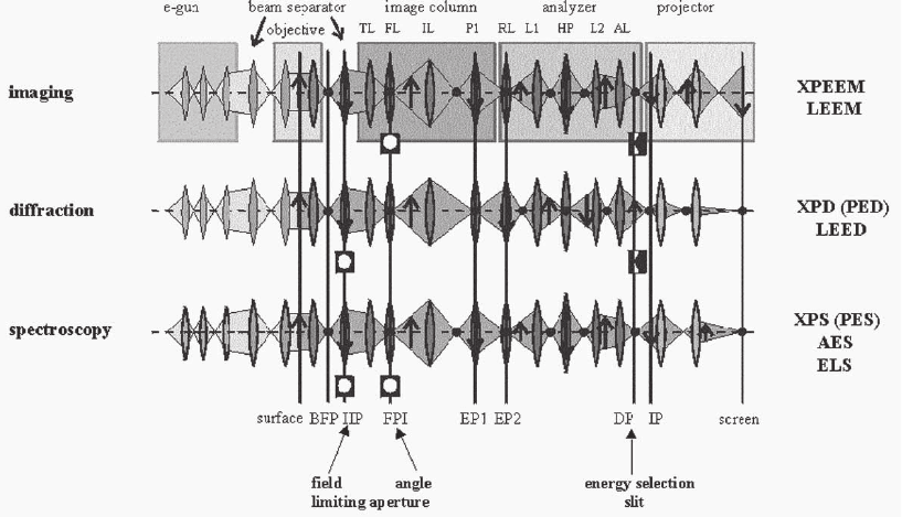
such an instrument are schemetically shown in Figure 8–18.
15,47
In
SEEM, whether excited by electrons, X-ray photons, or energetic ion/
neutrals, it allows selection of a narrow energy window from the wide
Figure 8–18. The three fundamental operation modes of a SPELEEM system. The various sections of
the instrument are shown folded into one plane. In imaging and diffraction the energy selection slit
is inserted in the dispersive plane DP and the image/diffraction pattern behind DP is imaged with
the projector. The intermediate lens IL is used to switch between imaging and diffraction, simultane-
ously with the exchange of the contrast aperture in FPI and the fi eld-limiting aperture in IIP. For fast
spectroscopy both apertures are inserted, the energy selection slit is removed, and the dispersive plane
is imaged by the projector.
15
(See color plate.)
624 E. Bauer
secondary electron energy distribution. This leads to a noticeable reso-
lution improvement, also in the aberration-corrected systems, in which
the correction rapidly deteriorates at low energies with decreasing
energy.
57
A number of different energy fi lters are used in these multi-
method instruments: one hemispherical analyzer, two hemispherical
analyzers, a Wien fi lter, or an Omega fi lter. As they are not essential
for LEEM they will not be discussed here.
For imaging with LEEM several contrast mechanisms are available,
depending upon the specimen to be imaged. The fundamental contrast
is diffraction contrast in crystalline samples or backscattering contrast
in amorphous or fi ne-grained crystalline materials. The origin of the
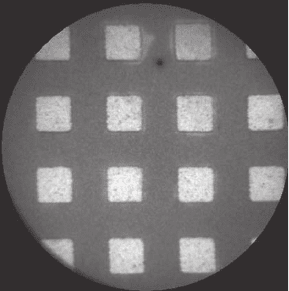
backscattering contrast is evident from Figure 8–1. An example of its
consequences is shown in Figure 8–19. Because of the higher backscat-
tering cross section of Co at the selected energy the fi ne-grained poly-
crystalline Co squares appear bright compared to the Si surrounding,
which is covered with native oxide. A slight preferred orientation of the
Co layer enhances the contrast.
78
In general, however, larger crystals or
single crystalline layers with a well-defi ned orientation are studied. In
this case not only the specular beam [(00) beam] but other diffracted
beams may be used for imaging. An atomically fl at single crystal surface
without steps and other defects produces contrast only when regions
with different crystal structure are present. A standard example is the
Si(111) surface when the unreconstructed (1 × 1) and reconstructed (7 ×
7) structure coexist. Here, both normal and lateral periodicity differ and
produce strong contrast (Figure 8–20a).
79
The Si(100) surface recon-
structs with the formation of dimer rows whose orientation rotates from
terrace to terrace by 90°, with constant normal periodicity. Here, the two
resulting (2 × 1) domains are equivalent at normal incidence and well-
centered aperture. Contrast is obtained by either tilting the incident
beam or shifting the aperture somewhat in the direction of one of the
rows. Using the ½ order spot of one of the domains gives maximum
contrast (Figure 8–20b).
80
Similar domain contrast can be obtained on all
Figure 8–19. Backscattering contrast
from 20-nm-thick Co squares on an Si
substrate. The electron energy is 5.1 eV
and the diameter of fi eld of view is
10 µm.
78
5 Contrast
