Hawkes P.W., Spence J.C.H. (Eds.) Science of Microscopy. V.1 and 2
Подождите немного. Документ загружается.

605
8
LEEM and SPLEEM
Ernst Bauer
Low-energy electron microscopy (LEEM: http://www.leem-user.com)
is an imaging method that makes use of elastically backscattered elec-
trons with energies below about 100 eV, frequently with less than 10 eV.
In contrast to transmission electron microscopy (TEM), which gener-
ally works with electrons in the 100 keV range where backscattering is
negligible, the backscattering cross sections for low-energy electrons
are large enough to make them useful for surface imaging. This was
already evident in the classical diffraction experiments of Davission
and Germer,
1
but it took 35 years before the use of slow diffracted
electrons for surface imaging was suggested
2
and another 23 years
before convincing images could be published.
3
Thus, although diffrac-
tion of slow electrons and imaging with slow emitted electrons with
resolution in the micrometer range were demonstrated
4
before TEM
reached submicron resolution,
5
LEEM became a viable imaging method
only much later.
The reasons for this late appearance of LEEM in electron microscopy
are 2-fold: (1) for LEEM well-defi ned surfaces are necessary, which in
general requires ultrahigh vacuum (UHV) and effi cient surface clean-
ing procedures. Although these have been available for some time in
glass systems such as in Farnsworth’s low-energy electron diffraction
(LEED) systems,
6–8
glass systems are not very user friendly and metal
UHV technology did not come into widespread use until the beginning
of the 1960s. In fact, the fi rst display type LEED system that started the
revival of LEED was a glass system
9,10
as was the fi rst unsuccessful
model of an LEEM system.
2
(2) There was the widespread belief in the
electron microscope community based on the fundamental theoretical
work of Recknagel on emission electron microscopy
11
that the chro-
matic aberration of the objective lens would limit the resolution to such
an extent that LEEM would be unattractive. This of course was a mis-
understanding as already pointed out in the early phase of the develop-
ment of LEEM.
12,13
In the decades since then LEEM has developed slowly
into a powerful surface imaging technique as recounted elsewhere.
14
1 Introduction

606 E. Bauer
In the past 10 years developments concentrated on the combination
of LEEM with X-ray induced photoemission electron microscopy
(XPEEM), which resulted in the spectroscopic photoemission and
low-energy electron microscope (SPELEEM),
15,16
and on the correction
of the aberrations of the objective lens.
17
Despite these efforts LEEM is
still far behind the technological state that TEM has now reached.
This chapter reviews the basics of LEEM, its present state of art, and
its applications. An associated imaging method, spin-polarized LEEM
(SPLEEM), which gives magnetic information, will also be discussed.
Other methods, such as mirror electron microscopy (MEM), which
gives information mainly on the local surface potential, Auger electron
emission microscopy (AEEM), which gives chemical information,
electron energy loss microscopy (EELM), which gives some electronic
information, and secondary electron emission microscopy (SEEM),
will be mentioned only briefl y because they have been used much less
frequently, although they are also useful. Photoelectron emission
microscopy (PEEM), in particular XPEEM, is included only in connec-
tion with the discussion of SPELEEM because it is the subject of another
chapter.
To understand the possibilities and limitations of LEEM and of the
associated techniques, a fundamental understanding of the interac-
tions of slow electrons with condensed matter is necessary. The follow-
ing interactions have to be taken into account: elastic scattering, inelastic
scattering, and quasielastic scattering (phonon and in magnetic materi-
als magnon scattering). The interactions of slow electrons with matter
are vastly different from those of fast electrons. In ferromagnetic
materials they depend in addition upon the relative orientation of the
spin of the incident electrons and the electrons in the matter.
Consider fi rst elastic scattering. Because of its low velocity
vEm= 2/
the interaction time of a slow electron is much longer than of the fast
electrons used in TEM and an n-electron atom may no longer be con-
sidered as undisturbed but becomes an n + 1 electron system during the
interaction. Therefore the incident electron experiences the temporary
excitations of the n-electron atom. This can be taken into account by
adding a correlation potential to the potential of the ground state n-
electron atom. Similarly the repulsive interactions between electrons
with the same spin due to the Pauli principle cause a spin-dependent
potential that also has be added. As a consequence, the scattering of slow
electrons by the atoms that constitute the condensed matter can no
longer be described by the fi rst Born approximation, which assumes a
static atom in the ground state and which is a good approximation at
high energies. Instead, a partial wave analysis is necessary, taking into
account the exchange and correlation potentials.
18,19
No calculations of
this type for condensed atoms, whose potentials are truncated by overlap
with the neighbor atoms, are available. Fortunately the magnitudes of
the correlation and exchange potential decrease rapidly with energy so
2 Electron Beam–Specimen Interactions
Chapter 8 LEEM and SPLEEM 607
that they may be neglected in the energy range of conventional LEED
studies (usually above 30 eV). In LEEM, however, they should be taken
into account. This is a formidable task that has not been mastered up to
now. Therefore, only some results of partial wave analysis calculations
for truncated ground state potentials will be given here.
In the partial wave analysis
20
the incident plane wave and the outgo-
ing scattered wave are expanded into spherical harmonics centered
at the atom, and the phase differences η
l
between the incident and
outgoing partial waves are calculated. In the nonrelativistic case the
scattering amplitude is given by
f(θ, k) = (1/2ik)Σ(2l + 1)[exp(2iη
l
− 1)]P
l
(cos θ) (1)
with the sum over l extending from zero to infi nity. k is the wave
number and the P
l
’s are Legendre polynomials. The intensity distribu-
tion of the scattered electrons as a function of scattering angle θ and
energy
Ek∼
is then simply ∼|f(θ, k)|
2
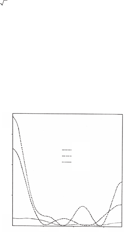
. Figure 8–1 shows the angular
distribution of the scattered intensity of 50 eV electrons, calculated in
this manner for realistic solid state Ag, Al, and Cu atomic potentials.
18
It shows that not only is the total scattering cross section of Cu (Z = 29)
smaller than that of Al (Z = 13), but also its back-scattering cross section,
and that Al scatters nearly as much as the much heavier Ag atom
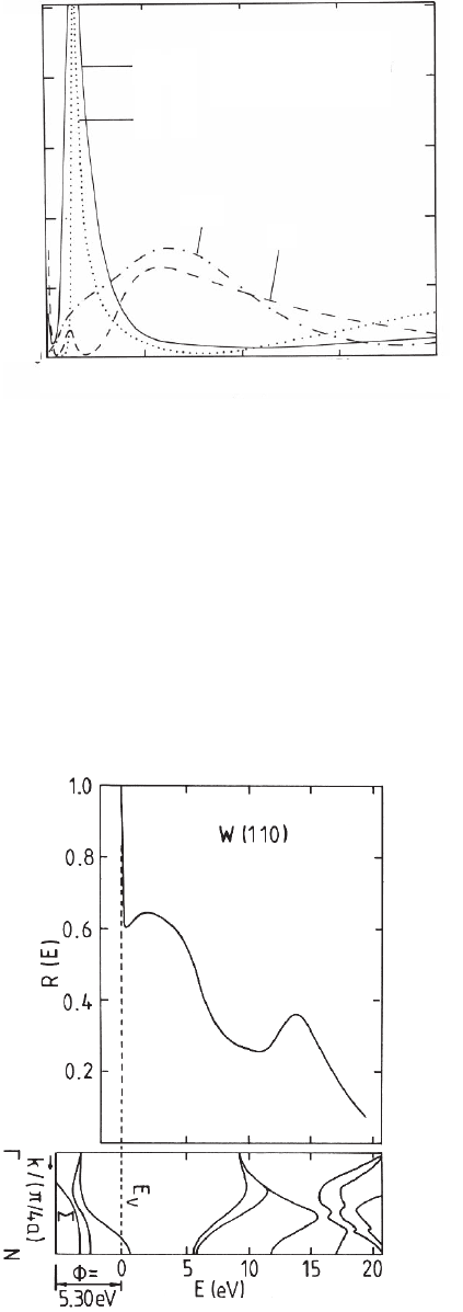
(Z = 47). The scattering is, however, strongly energy dependent. This is
illustrated for the scattering into a 30° cone around the backward direc-
tion in Figure 8–2,
19
which shows that at very low energies Cu scatters
nearly as strongly as W (Z = 74) while Al and Ag scatter much more
weakly in the backward direction. It should be noted that the zero of
the energy is the inner potential resulting from the overlap of the free
atom potentials so that the maxima of the W and Cu backscattering
cross sections are just around the vacuum level.
Figure 8–1. Angular distribution of 50 eV electrons elastically scattered from
Ag, Al, and Cu atoms in the solid state.
18
Ag
15
10
5
0° 50°
υ
150°
100°
Al
Cu
I (u) (a
0
2
)
608 E. Bauer
In condensed matter the electrons are, of course, not only scattered
within one atom but also by the atoms surrounding it, causing strong
multiple scattering. This is taken into account in LEED in the dynamic
theory of electron diffraction.
21,22
Another way to look at the problem
of scattering in a periodic system is in terms of the band structure
theory if we assume that the n + 1-electrons system (n crystal electrons
+ incident electron) does not differ signifi cantly from the n-electron
system (Koopman’ theorem
23
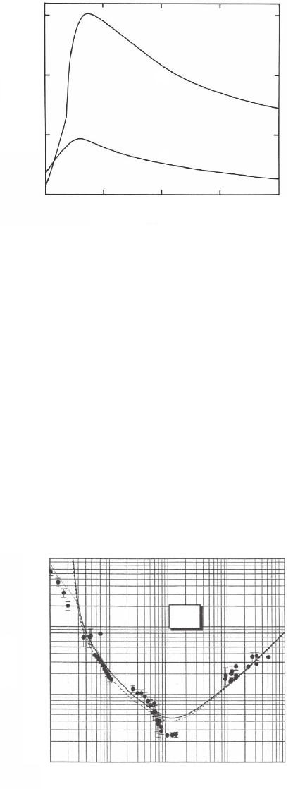
). Then the 180° backscattering from a
single crystal surface is determined by the band structure E(k) perpen-
dicular to the surface. This is illustrated in Figure 8–3 for the W(110)
surface.
24
The band structure in the [110] (ΓN) direction has a wide
Backscattering into
angular region from
150° to 180°
W
Cu
Ag
0
050100 150 200
1
2
Al
E (eV)
QR (Å
2
)
Figure 8–2. Energy
dependence of the
backscattering into a
30° cone around the
backward direction for
Ag, Al, Cu, and W
atoms in the solid
state.
19
Figure 8–3. Normal incidence
specular refl ectivity of a W(110)
surface (top) and band struc-
ture along the surface normal
(bottom).
24
Chapter 8 LEEM and SPLEEM 609
band gap between about 1 and 6 eV above the vacuum level. An elec-
tron incident in this direction, therefore, does not fi nd allowed states
in the crystal and forms an evanescent wave. The extinction length of
this electron wave in the crystal is quite short in the center of the gap,
only about two monolayers,
25
so that the electron is refl ected before it
is attenuated signifi cantly by inelastic scattering. This, together with
the strong backscattering cross section, causes the high refl ectivity at
about 2–3 eV. The second refl ectivity peak is due to the low density of
states in the crystal as indicated by the steep bands. The band structure
infl uence is strongly orientation dependent. For example, on the W(100)
surface the band gap is located between 3 and 5 eV above the vacuum
level,
24,26
which causes a pronounced refl ectivity peak at about 4 eV.
This is preceded by a deep refl ectivity minimum, which is caused by
the strong inelastic scattering of the electron that could otherwise
penetrate deeply into the crystal. A second refl ectivity peak occurs
around 8 eV where the density of state in the crystal is small. This
simple picture neglects the infl uence of surface effects. For quantitative
agreement between experiment and theory the surface barrier,
27
surface
resonances,
24
and reconstruction have to be taken into account. For
LEEM these details are not important, at least at the present state of
art, because they determine mainly the refl ected intensity and have
little infl uence on the contrast.
The main factor that determines the high surface sensitivity of LEEM
is in general not the infl uence of the band structure and of elastic scat-
tering but the strong attenuation of slow electrons by inelastic scatter-
ing. Inelastic scattering is due to single electron excitations (electron
hole pair creation) and collective electron excitations (plasmon cre-
ation). In the energy range of LEEM single electron excitations mainly
involve valence band and weakly bound outer shell core electrons. The
universal inelastic mean free path (IMFP) curves usually found in the
literature are of rather limited value at the low energies used because
they do not take into account the differences in the electronic structure
of the various materials. Therefore, only some general features will be
discussed and some specifi c examples will be given. In materials that
may be described approximately by a free electron gas imbedded in a
homogeneous background of equal charge (“jellium model”) the IMFP
is a function of k/k
F
(k
F
Fermi wave number) with the electron density
as parameter.
18,19,28
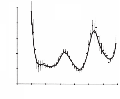
As an example, the attenuation length µ = (IMFP)
−1
of Al, for which the free electron approximation is good, is shown in
Figure 8–4 together with the attenuation coeffi cient ν due to elastic
backscattering, assuming a random distribution of Al atoms with bulk
density (“randium model”).
29,30
The initial rise of µ until the volume
plasmon creation threshold at E
T
= 17.5 eV (above vacuum level) is due
to single electron excitations. The maximum of µ and the corresponding
minimum of about 0.3 nm of the IMPF at about 37 eV is mainly due to
plasmon losses. Figure 8–4 also shows that attenuation by elastic back-
scattering is much weaker above E
T
than that by inelastic scattering.
For most metals the jellium approximation is not useful, in particu-
lar for transition and noble metals. For example, in contrast to jellium,
transition metals have a high density of unoccupied states just above
610 E. Bauer
the Fermi level into which excitations can occur. The deviation from
jellium can be partially taken into account by replacing the ω depen-
dence in the Lindhard dielectric function ε
L
(ω, q), which is used in the
jellium calculations, by that obtained in the experiment for zero
momentum q transfer, that is by optical data for which q = 0. Results
of such calculations
31
give typically minimum IMFPs in metals of
0.3–0.5 nm at energies between 30 and 120 eV for Mg and Au, respec-
tively, with a rapid increase at low energies to values as high as 2.4 nm
in Si and 3.5 nm in W at 10 eV, for example. Figure 8–5 illustrates the
agreement between theory and experiment that can be obtained in
this approximation.
32
The deviations below E − E
F
= 5 eV are irrelevant
for LEEM because the work function of Au is about 5 eV; those above
50 eV are probably due to inaccurate 5p and 4f ionization cross
0.1
0.2
0.3
50 100 150 200
E
Vac
(eV)
µ
µ,ν (Å
–1
)
ν
Figure 8–4. Energy dependence of the attenuation coeffi cients µ,ν of slow elec-
trons in Al by inelastic scattering and elastic backscattering, respectively.
29
10
0
10
0
10
–1
10
1
10
1
10
2
10
2
10
3
10
4
E–E
F
(eV)
λ
in
(nm)
Au
Figure 8–5. Energy dependence of the inelastic mean free path of electrons
in Au. The points and dots are experimental data and the dashed and solid
lines are theoretical data using different approximations.
32
Chapter 8 LEEM and SPLEEM 611
sections. The agreement is surprisingly good considering that the q
dependence of ε has been approximated by simple expressions and
that correlation and exchange have not been taken into account. At
energies below several 10 eV these are of comparable importance for
inelastic scattering as for elastic scattering, in particular the infl uence
of the detailed band structure and of nondirect (q # 0) transitions.
33
For example, inclusion of exchange in the dielectric model of the IMFP
gives IMFP values that are by a factor of 1.3 and more larger than
without exchange.
34
The IMFPs calculated in this approximation for insulators are even
larger, such as 6 nm at 10 eV for KCl.
31
For several groups of insulators
with large band gaps (condensed noble gases, N
2
, and organic dielec-
trics such as benzene or methane) no electronic excitations are possible
at low energies. Here the (quasi)elastic mean free path (EMFP) deter-
mines the sampling depth. EMFP measurements in the energy range
from 2 to 15 eV give EMFPs up to 10 nm.
35
An example is shown for
solid Xe in Figure 8–6.
36
Thus the MFP may be very long at low ener-
gies (≤10 eV) while at energies between about 30 eV and 100 eV, depend-
ing upon the material, it may be only a few tenths of a nm. The large
mean free paths (MFPs) at very low energies are, however, not general.
They depend strongly on the density of unoccupied states into which
bound electrons can be excited as clearly evident in an insulator with
wide band gaps.
35
These are extreme cases inasmuch as their band
gaps are so large that the density of unoccupied states becomes
signifi cant only at several electronvolts above the vacuum level. At the
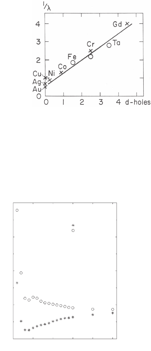
other extreme are transition metals with their unfi lled d bands with
high density of states just above the Fermi level. Here the IMFPs are
very short as seen in Figure 8–7
37
in which the reciprocal values of the
IMFPs are plotted as a function of the number of d holes. The values
shown are for electrons with energies between 5 and 10 eV above the
Fermi energy. For Fe the IMFP is only about 0.5 nm and for Gd only
Solid Xe
T = 45 K
2
2
6
10
345678
Electron Energy (eV)
Mean Free Path (nm)
Figure 8–6. Energy dependence of the elastic mean free path of slow electrons
in solid Xe.
36
612 E. Bauer
0.25 nm. In ferromagnetic materials the density of unoccupied states
differs between majority and minority spin states, which causes
corresponding differences in the excitation probabilities. Calculations
that take this into account show a signifi cant difference between the
IMFPs of incident electrons with majority and minority spin as seen
in Figure 8–8.
38
The zero of the energy is the Fermi energy; the work
Figure 8–7. Reciprocal inelastic mean free path in nm
−1
of electrons with ener-
gies between 5 and 10 eV above the Fermi level as function of the number of
holes in the 3d and 4d shell.
37
spin down
0
5
10
15
20
0.0 5.0 10.0 15.0 20.0 25.0
Electron Energy (eV)
IMFP(Å)
spin up
Figure 8–8. Energy
dependence of the inelas-
tic mean free path of
majority and minority
spin electrons in Fe.
38
Chapter 8 LEEM and SPLEEM 613
function of Fe is 4.5 eV so that 1 eV above the vacuum level the IMFPs
are only 0.6 and 0.2 nm for majority and minority spin electrons,
respectively. At 10 eV above the vacuum level the corresponding values
are 0.45 and 0.3 nm, which are much lower than the 1.6 nm obtained
from the dielectric theory discussed above. For more information see
Bauer.
39
While the knowledge of reliable absolute numbers for elastic and
inelastic mean free paths at low energy is still limited, the infl uence
of phonon and magnon excitation on the effective sampling depth is
much less understood. Both processes involve only small energy
losses up to several 100 meV but can occur with large momentum
transfer. In LEEM only the electrons in a diffraction spot and its
immediate environment contribute to the image formation. Therefore
energy losses with momentum transfer larger than that determined
by the radius of the contrast aperture cause an attenuation of the
intensity contributing to the image formation. At not too high tem-
peratures this can be taken into account by the Debye–Waller factor.
At higher temperatures multiphonon and -magnon excitations occur
that cause an increased attenuation, which may be described by an
anharmonic Debye–Waller factor.
40
In this conventional description of
the infl uence of phonons on the scattering from surfaces there is no
thickness dependence. However, in thin fi lms the number of electrons
scattered outside the contrast aperture increases with increasing
thickness so that an effective attenuation coeffi cient could be defi ned.
This has not been done to date for several reasons: (1) there are no
numbers for the cross sections for phonon and magnon scattering that
could be compared with those for inelastic scattering, (2) with increas-
ing temperature there is frequently atomic disordering that causes
diffuse scattering, and (3) at high temperatures thin fi lms usually
break up into three-dimensional crystals before attenuation by these
processes becomes signifi cant. A rough idea of the infl uence of thermal
vibrations on the attenuation length may be obtained from the analy-
sis of LEED patterns from Cu single crystal surfaces. At 50 eV the total
attenuation length, which includes elastic backscattering, inelastic
scattering, and phonon scattering, from the (111) surface is 0.33 nm at
300 K versus 0.34 nm at 0 K.
41
The difference is well within the limits
of error of the values so that at least at this energy phonon scattering
does not limit the sampling depth.
According to the present state of understanding the sampling depth
of LEEM and SPLEEM is primarily determined by inelastic and elastic
backscattering. Depending upon the energy and electronic structure
of the material, the sampling depth may be as small as a few tenths of
a nanometer, for example, around the plasmon excitation maximum,
in transition metals with a high density of unoccupied states above the
Fermi level, or in band gaps along the k direction normal to the surface.
On the other hand, sampling depths as large as several nanometers
can occur at very low energies, for example, in insulators and free
electron like metals. In many cases this allows tuning of the sampling
depth by proper choice of the energy, which makes LEEM and SPLEEM
ideal for imaging of surfaces and thin fi lms.
614 E. Bauer
The electron optics of an LEEM/SPLEEM instrument in the imaging
section is essentially the same as in emission electron microscopes,
which date back to the 1930s. In these microscopes the specimen is the
cathode of a so-called cathode lens in which the slow emitted electrons
are accelerated in a high fi eld to the fi rst of several image-forming elec-
trodes of an electrostatic lens or to the entrance of a magnetic lens. This
lens is the objective lens of the microscope, which produces a primary
image with fast electrons. The subsequent electron optics is basically
the same as in TEM. In fact, the fi rst objective lens used in LEEM was a
modifi ed version of an electrostatic triode lens developed for PEEM.
42
To do LEEM with such a system fast electrons have to be injected from
the high-energy side of the objective lens along its optical axis. In the
cathode lens they are decelerated to the desired low energy at the speci-
men. To be able to produce an image, this incident beam has to be sepa-
rated from the refl ected beam by a beam divider. As a consequence an
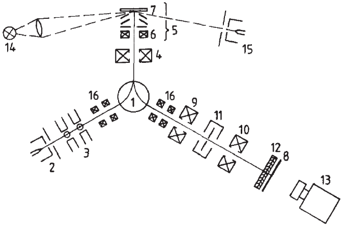
LEEM or SPLEEM system has a bent optical axis. A schematic of the fi rst
instrument is shown in Figure 8–9.
3
The beam separator (1) defl ects the
incident beam from a fi eld emission gun (2) that is focused by two
quadrupoles (3), the defl ection fi eld (1), and optionally by a collimator
lens (4) into the back focal plane of the objective lens (5). They reach the
specimen (7) on parallel trajectories with an energy that is determined
by the adjustable potential difference between fi eld emitter and speci-
men. The specimen is imaged by the elastically refl ected electrons into
the center of the beam separator, its diffraction pattern into the back
focal plane of the objective lens where the angle-limiting contrast aper-
ture is located. The astigmatism of the objective lens is corrected with
Figure 8–9. Schematic of the fi rst LEEM instrument. For explanation see text.
3
3 Instrumentation
