Hawkes P.W., Spence J.C.H. (Eds.) Science of Microscopy. V.1 and 2
Подождите немного. Документ загружается.

Chapter 8 LEEM and SPLEEM 625
reconstructed surfaces on which reconstruction domains exist with dif-
ferent azimuthal orientations. All surfaces have steps or step bunches
that will produce another contrast to be described below.
In general surfaces are heterogeneous not only in crystallography
but also in composition and topography. Composition differences are
usually connected with crystallographic differences and produce,
together with backscattering differences, diffraction contrast in the (00)
beam. Also here imaging with nonspecular beams is useful for identify-
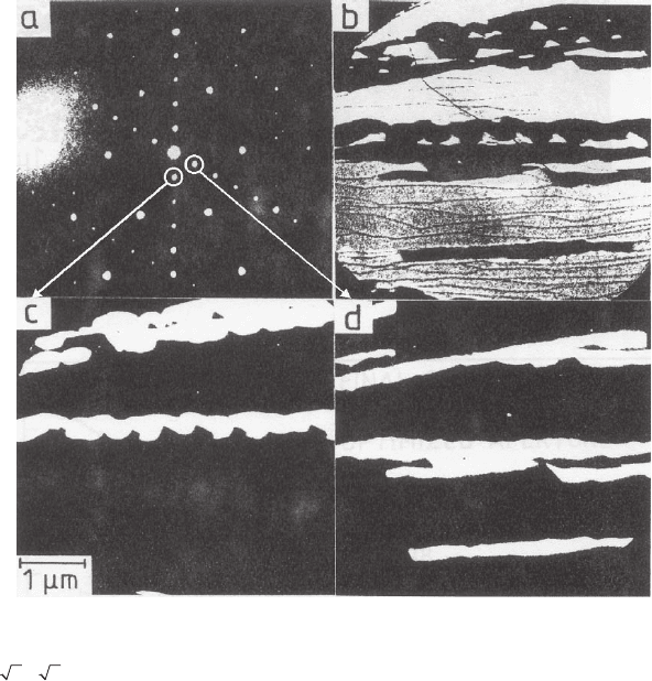
ing different coexisting phases as illustrated in Figure 8–21,
81
which is
from an Si(111) surface covered with a submonolayer of Au. The three
LEEM images are taken with the (00) beam and with nonspecular beams
(1/5-order beams) of (5 × 2) superstructure domains. This allows the
identifi cation of the dark regions between the bright (
33×
)-R30°
structure regions in the specular image with different (5 × 2) domains.
Topography distorts the electric fi eld distribution on the surface.
This causes the usual topographic contrast, which is most evident near
zero electron energy. Topography also produces diffraction contrast.
This happens when surface elements are inclined against the average
surface, for example, in small crystals on an otherwise fl at surface. In
a LEEM instrument the positions of the LEED spots from a fl at surface
do not change with energy as they do in an ordinary LEED system.
This is due to the fact that the observed LEED pattern is a magnifi ed
image of the LEED pattern in the back focal plane of the objective lens,
where the electrons have a constant high energy E = (h
2
/2m)k
2
inde-
pendent of their start energy. Because the wave number k is propor-
tional to the refractive index n, we have
k sin θ = k
o
sin θ
o
(2)
where θ and θ
o
are the angles of the electron trajectories with the
optical axis in the back focal plane and at the surface, respectively. For
two-dimensional diffraction
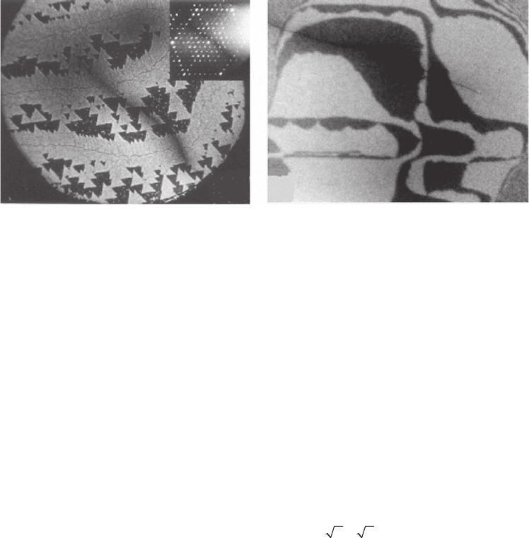
Figure 8–20. Diffraction contrast from Si surfaces. a) Si(111). (Normal incidence) contrast due to dif-
ferent normal periodicity of coexisting (1 × 1) (dark) and (7 × 7) (bright) structure. Electron energy
10 eV, diameter of fi eld of view 6 µm. Inset: LEED pattern.
79
b) (Oblique incidence) contrast due to dif-
ferent azimuthal orientation of coexisting (2 × 1) and (1 × 2) domains. Electron energy 6 eV, image
width 3 µm.
80
a)
b)
626 E. Bauer
k sin θ
o
= 2πh (3)
where h is the distance of the LEED spot h = (h
1
, h
2
) from the (00) beam,
which is on the optical axis at normal incidence. Combining the two
equations leads to
k sin θ = 2πh (4)
Thus the angular distance θ of the LEED spot h in the back focal plane
is independent of the start energy E
o
= (h
2
/2m)k
2
o
and depends only on
the fi nal energy E = (h
2
/2m)k
2
. This is no longer true when the surface
normal is inclined against the optical axis. Then the specular beam is
off-axis and the diffracted beams h move toward the specular beam
with increasing energy. The simple geometric relations at normal inci-
dence, which lead to E
o
-independent spot positions, are no longer valid
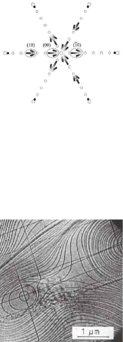
so that the spots move now in the back focal plane. An example of these
spot movements is shown in Figure 8–22.
82
A simple geometric analysis
allows deduction of the inclination of the surface.
Faceted surfaces, that is surfaces on which all surface elements are
tilted, so that no specular beam is on the optical axis, can be imaged
either by selecting an energy at which one of the diffracted spots passes
Figure 8–21. Phase identifi cation by dark-fi eld imaging. The LEED pattern (a)
of the Au submonolayer on Si(111) shows a hexagonal pattern from the
(
33×
)-R30° phase and two linear patterns from the (5 × 2) phase. The
bright-fi eld image (b) shows dark regions that are identifi ed as (5 × 2) regions
by imaging with (1/5, 0), spots (c and d). Electron energy in (a) 30 eV and in
(b–d) 6 eV.
81
Chapter 8 LEEM and SPLEEM 627
through the optical axis or by tilting the illuminating beam or by shift-
ing the contrast aperture off axis into one of the specular beams. For
large tilt angles only the fi rst mode is practical.
Another important contrast mechanism is the interference contrast
on fl at surfaces with height differences such as atomic steps. The step
contrast was already observed in the early studies (Figure 8–23
1
) and
attributed to destructive interference between the wave fi elds refl ected
from the adjoining terraces within the lateral coherence length (Figure
Figure 8–22. Drawing of the movements of LEED spots from faceted Cu sili-
cide crystallites on a Si(111) surface. The open circles are from the Si(111)-δ(7
× 7) structure. The small solid and shaded circles are from the crystallites.
Increasing shading shows the movement of the spots with energy increasing
from 3 to 10.5 eV.
82
Figure 8–23. Monatomic steps on an MO(110) surface. Electron energy
14 eV.
3

628 E. Bauer
8–24a). Detailed model calculations based on Fresnel diffraction from
two adjoining straight edges shifted relative to each other by the step
height produce all salient features of the step contrast.
83,84
Here some
results of the general theory of image formation by a typical magnetic
cathode lens will be given.
85
In the absence of aberrations the refl ection
of slow electrons from a point source would produce an interference
pattern that extends far out from the step. This would make image
interpretation in the presence of several steps diffi cult. The spherical
aberration reduces the range of the interference pattern signifi cantly
and the chromatic aberration reduces it to one intensity maximum next
to the step at energy spreads as low as 0.5 eV. The intensity distribution
around the step depends upon the phase difference between the waves
refl ected from both sides of the step, that is upon the step height and
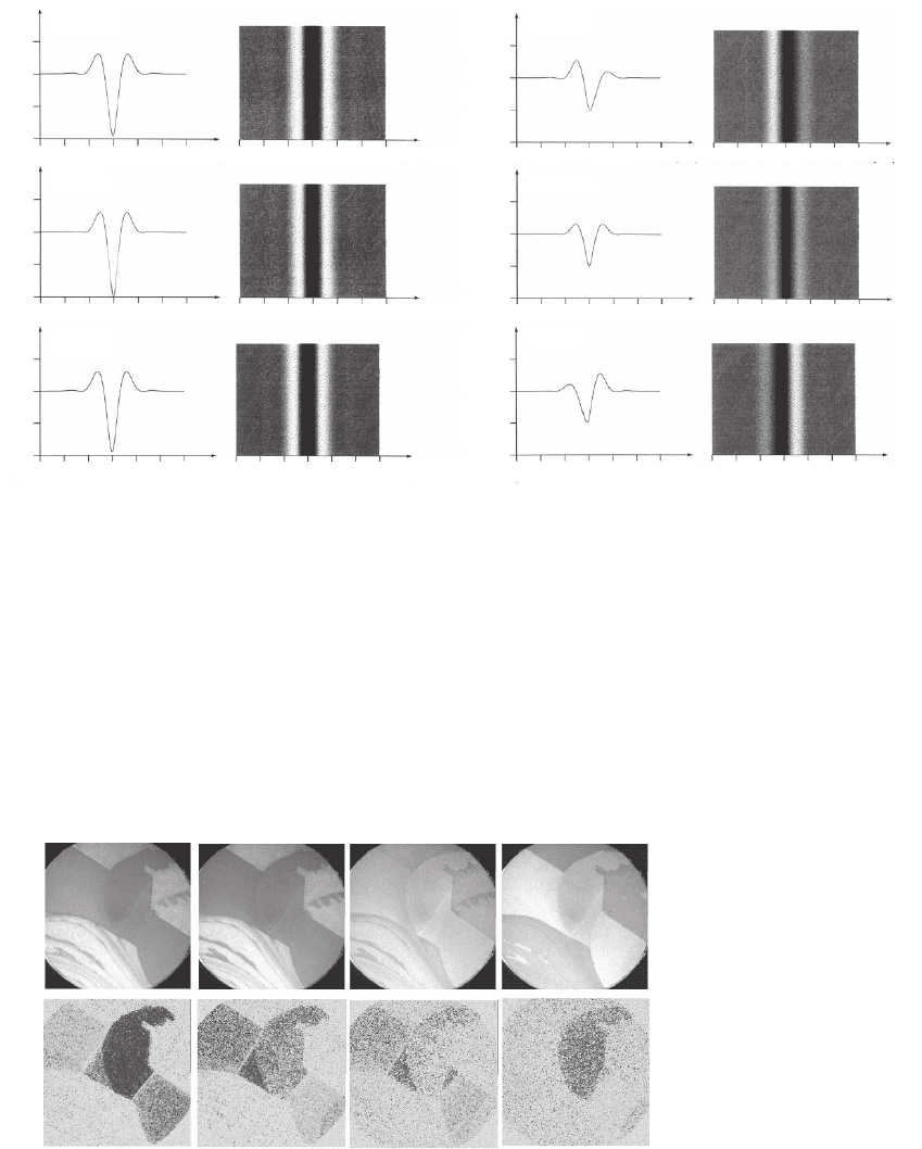
the wave length, and upon the defocus. This is illustrated in Figure 8–
25
85
for two phase shifts ∆ϕ = nπ (n = 0.5, 1) and several defocus values
∆z* = ∆z(C
s
λ)
−1/2
, where ∆z is the geometric defocus, C
s
the spherical
aberration constant, and λ the wavelength. ∆z* = 0, 1 corresponds to the
Gaussian image and to the Scherzer focus, respectively. For integer n
the step contrast is symmetric and optimum at ∆z* = 0; for noninteger
n it is asymmetric, with the bright edge changing from one side of
the step to the other when the sign of the defocus changes. Optimum
contrast is achieved for slight defocus.
A third contrast mechanism, the quantum size contrast, is also based
on wave interference, which not necessarily requires crystal periodic-
ity. In a thin fi lm bounded by two parallel surfaces the wave refl ected
from the bottom surface can interfere constructively or destructively
with that refl ected from the top surface similar to a Fabry–Perot inter-
ferometer, depending upon the wavelength λ, the thickness t, and the
phase shifts ϕ upon refl ection at the surfaces (Figure 8–24b). Construc-
tive interference and therefore enhanced refl ect ivity occurs whenever
n(λ/2) + ϕ = t, where n is an integer and λ is the wavelength in the fi lm,
which differs from the vacuum wavelength by the inner potential. As
a consequence, regions with different thickness appear in the image
with different brightness. This was fi rst observed in Cu fi lms on
Mo(110)
86
and has been studied since in detail in several other systems
with the goal to determine the band structure k(E) above the vacuum
Figure 8–24. Conditions for phase contrast in LEEM. (a) Step contrast. (b) Quantum size contrast. The
penetration of the electron wave upon refl ection is indicted.
Chapter 8 LEEM and SPLEEM 629
level,
83,87,88,89
spin-dependent electron refl ectivity effects,
90
or to under-
stand specifi c features in thin fi lm growth.
91,92,93
To determine the band structure, the constructive interference con-
dition above is rewritten by replacing λ by k = 2π/λ, which leads to
k(E)t − k(E)ϕ(E) = nπ. The energy-dependent phase term can be elimi-
nated by choosing fi lm thickness pairs t
1
, t
2
for which this condition is
fulfi lled (with different n), which gives a set of k(E) values. With proper
growth conditions regions with different thickness can be obtained
(Figure 8–26
87
) and analyzed quasisimultaneously. After subtraction of
I
∆ z* = –2
∆
z* = –2
∆
z* = 0
∆
z* = 0
∆ z* = 2 ∆ z* = 2
1.50
1.00
0.50
0.00
I
1.50
1.00
0.50
0.00
I
1.50
1.00
0.50
0.00
I
1.50
1.00
0.50
0.00
I
1.50
1.00
0.50
0.00
I
1.50
1.00
0.50
0.00
–30 –30–20 –20–10 –100010 1020 2030 30x[nm]
x[nm]
–30 –30–20 –20–10 –100010 1020 2030 30x[nm] x[nm]
–30 –30–20 –20–10 –100010 1020 2030 30
x[nm]
x[nm]
–30 –30–20 –20–10 –100010 1020 2030 30
x[nm]
x[nm]
–30 –30–20 –20–10 –100010 1020 2030 30
x[nm]
x[nm]
–30 –30–20 –20–10 –100010 1020 2030 30
x[nm]
x[nm]
Figure 8–25. Step contrast for the phase differences ∆ϕ = π (left) and ∆ϕ = 0.5π (right) between the
waves refl ected from the terraces next to the step for zero defocus and small positive and negative
defocus.
85
5.2 eV 6.4 eV 9.6 eV 11.4 eV
6ML
7ML
8ML
Figure 8–26. Quantum size contrast between regions with different thickness
of an Fe fi lm on W(110), taken with different electron energies, that is wave-
lengths. The images in the top row show the intensity and those at the bottom
the magnetic signal (exchange asymmetry). Blue and red correspond to oppo-
site magnetization directions.
88
(For the bottom row, see color plate.)
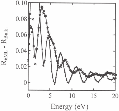
630 E. Bauer
the refl ectivity of a thick fi lm, which does not show quantum size
effects, the oscillations of the refl ectivity due to constructive and
destructive interference can clearly be seen. This is illustrated in Figure
8–27
91
for a ferromagnetic fi lm in which the band structures of the
majority and minority spin electrons differ by the exchange splitting.
The refl ectivity curve for the minority spin electrons is shifted relative
to that of the majority electrons due to this splitting and is also damped
which allows rapid image acquisition, the high surface sensitivity, which
strongly accentuates the topmost layer in imaging, both discussed in
have made LEEM one of the most powerful methods for surface studies,
in particular of the thermodynamics of surfaces and of the kinetics of
surface processes. While most of this information came from detailed
studies of semiconductor surfaces, mainly from Si(111) and Si(100) sur-
faces, important insight into surface processes have also been obtained
from various metal surfaces and oxide surfaces such as the TiO
2
(110)
surface. The information obtained from such studies ranges from the
chemical potential of adatoms, diffusion across terraces and steps,
anisotropic step free energy, step stiffness, step mobility, step–step
interactions, surface free energy and surface stress, vacancy exchange
between the bulk and the surface to nucleation, growth, phase transi-
Figure 8–27. Quantum size oscillations of the refl ectivity of spin-up (•) and
spin-down (*) electrons in a six-monolayer-thick Fe fi lm on W(110) as a func-
tion of energy.
88
6 Applications
more strongly due to the shorter IMFP of the minority electrons men-
6.1 General Comments
tioned in Section 2.
The high intensity available in LEEM studies of single-crystal surfaces,
Section 2, and the various contrast mechanisms described in Section 5
Chapter 8 LEEM and SPLEEM 631
tions, self-organization, faceting, segregation, oxidation, and other
surface and thin fi lm phenomena. Only some examples can be men-
tioned in the following subsections. These are organized according
to the material, but the references will provide access to most of the
relevant work done up to now. For illustrations results of the early,
exploratory work will be used because the later quantitative studies
require much more discussion.
The Si(111) surface is probably the surface most studied with LEEM,
mainly because of its phase transition from the reconstructed (7 × 7)
to the disordered “(1 × 1)” at 1100 K or 1135 K, depending upon author.
In precise LEED diffractometer measurements,
94
see also
95
the super-
structure spots disappeared at 1120 K and an intensity fi t assuming a
continuous transition gave a critical temperature of 1100 K ± 1 K.
However, no critical scattering was observed, which put into question
earlier conclusions that the phase transition was second order. The fi rst
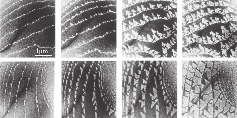
LEEM measurements
79,80,96
demonstrated with out doubt that the transi-
tion was fi rst order as seen in the nucleation and growth of the (7 × 7)
structure (Figure 8–28). The growth rate of the (7 × 7) domains was
found to increase linearly with undercooling ∆T and for ∆T > 12 K
nucleation also occurred on the terraces.
The transition was found to be strongly infl uenced by impurities.
97
In particular, the apparent discrepancy between LEEM and the preced-
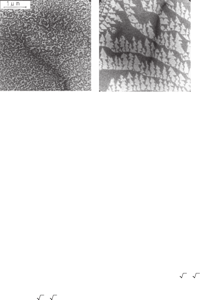
ing LEED studies could be attributed to near-surface contamination
during the long measurement time near the phase transition needed
in the quantitative LEED studies. This is illustrated in Figure 8–29,
80
which shows that long annealing near the transition temperature
Figure 8–28. Nucleation and growth of the (7 × 7) structure at surface steps with different orientations
at low supersaturation. Electron energy: top 10.5 eV and bottom 1.5 eV.
96
6.2 The Si(111) Surface
632 E. Bauer
completely destroys the regular domain structure. The LEED patterns
differ only by a slightly higher background in the annealed sample but
the transition range is now much wider, similar to that in the LEED
studies. On clean surfaces that have been quenched rapidly and have
converted completely into the (7 × 7) structure many domains with
various sizes form. Upon subsequent annealing they coarsen without
preference of certain boundary orientations and number of bounding
domain walls.
98
Recent, more detailed studies
99–109
have shed considerable light on
the forces and processes involved in the phase transition, such as
adatom diffusion,
99,100,104
the infl uence of the surface stress difference
between the (7 × 7) and (1 × 1) phases and of long-range interactions
on phase coexistence,
101
shape,
105,109
and distribution of the (7 × 7)
domains
106
and other aspects. There are excellent reviews on these
subjects
110,111
where details may be found. Another phenomenon that
has been studied with LEEM and that is closely related to the (1 × 1)
to (7 × 7) phase transition upon cooling is the faceting of vicinal
(stepped) Si(111) surfaces.
112–114
Other studies have been concerned with
the conditions for step fl ow growth instead of two-dimensional nucle-
ation from which the parameters that determine the growth kinetics
can be derived.
115–117
In and Sb surfactants that form a (
33×
)R30°
structure were found to either enhance or to suppress step fl ow, respec-
tively.
118
An apparently similar boron-induced surface structure
[(
33×
)R30°–B] has a quite different effect: it causes twinning.
115
This surface is the basis of semiconductor technology and has, there-
fore, attracted particular attention. It was studied qualitatively in the
early years of LEEM
80
(see Figure 8–20b) and showed convincingly the
inequivalence of the A and B type steps, the lower energy S
A
steps
being smooth while the higher energy S
B
steps were rough. Step migra-
Figure 8–29. Comparison of a surface that had been annealed for a long time around the transition
temperature (a) and one that has been cooled rapidly from 1450 K to this temperature (b). Electron
energy 10.5 eV.
80
6.3 Si(100)
Chapter 8 LEEM and SPLEEM 633
tion during sub limation
119
and interaction with dislocations formed by
plastic deformation during cooling
120
were studied as well as the
enhancement of one domain upon elastic defomation.
80,120
Other pro-
cesses included consecutive “Lochkeim” formation during sublimation
of fl at regions
121
and homoepitaxial growth.
80,121–123
From the terrace
shape during growth close to equilibrium (Figure 8–30) a lower limit
of the ratio of the step free energies of S
B
and S
A
of β
B
/β
A
≥ 2.6 at about
800 K was obtained. In other qualitative work
124,125
the step morphology
was studied in more detail as a function of miscut angle, which led to
a step “phase diagram” ranging from a “hilly” phase near zero miscut
via single height wavy steps, straight steps to double height steps at a
miscut of about 0.1°.
In subsequent quantitative studies
126–137
comprehensive information
could be deduced from step and island shapes and distributions. Many
of the results can also be found in the reviews mentioned above.
110,111
Some of them are the determination of the mobility and stiffness of the
S
A
and S
B
steps,
126,130
of their free energy,
126
and of the anisotropy of the
surface stress;
137
the extraction of the chemical potential, formation
energy, and diffusion coeffi cients of adatoms from number, area, and
distribution of two-dimensional islands.
127,131,134
On the more qualitative
side, the fabrication of large step-free regions
129,136
and of periodic
gratings
132,133,135
by e-beam lithography, reactive ion beam etching,
and high-temperature annealing has also contributed considerably to
the understanding of the surface properties. Other methods of surface
modifi cations have been studied as well. Oxygen etches the surface at
high temperature and produces vacancy islands.
138,139,140
Arsenic was
found to displace Si even on large terraces, driven by surface stress,
Figure 8–30. Images from a video taken during the homoepitaxial growth of
Si(100) at low supersaturation so that growth can occur only from a defect at
the lower edge of the image. Electron energy 5 eV.
122

634 E. Bauer
causing two-dimensional island formation.
141
Boron segregation leads
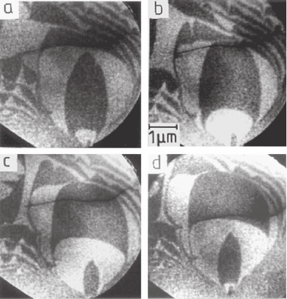
to strong temperature-dependent surface roughening at the monolayer
level, forming a striped (Figure 8–31) or triangular-tiled surface
structure.
142–145
Originally believed to be driven mainly by surface stress
relaxation
142
it was shown later that a strong reduction of the step free
energy of the S
A
steps was the main driving force.
143,144
On the silicon-on-insulator (SOI) (100) surface LEEM was used to
determine the dislocation-induced strain.
146
On the Si(311) surface the
LEEM image intensity fl uctuations in small surface regions were mea-
sured during the continuous disordering transition of the (3 × 1) recon-
struction around 965 K, in order to determine the critical parameters.
147
Figure 8–31. Images
from a video taken
during the segregation
and desegregation of B
from B-doped Si(100)
during cooling and
heating. Electron energy
4.2 eV; diameter of fi eld
of view 7 µm.
6.4 Other Elemental Semiconductor Surfaces
